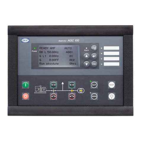
Deif GPC-3 Hydro User manual

DEIF A/S · Frisenborgvej 33 · DK-7800 Skive · Tel.: +45 9614 9614 · Fax: +45 9614 9615 · info@deif.com · www.deif.com
DEIF A/S · Frisenborgvej 33 · DK-7800 Skive · Tel.: +45 9614 9614 · Fax: +45 9614 9615 · info@deif.com · www.deif.com
DEIF A/S · Frisenborgvej 33 · DK-7800 Skive · Tel.: +45 9614 9614 · Fax: +45 9614 9615 · info@deif.com · www.deif.com
DESIGNER’S REFERENCE HANDBOOK
Generator Paralleling Controller
GPC-3/GPC-3 Gas/GPC-3 Hydro
● Functional description
● Modes and sequences
● General product information
● PID controller
● Additional functions
Document no.: 4189340587L
SW version: 3.09.x or later

1. General information
1.1. Warnings, legal information and safety.................................................................................................. 5
1.1.1. Warnings and notes ......................................................................................................................5
1.1.2. Legal information and disclaimer ..................................................................................................5
1.1.3. Safety issues ................................................................................................................................ 5
1.1.4. Electrostatic discharge awareness ............................................................................................... 5
1.1.5. Factory settings ............................................................................................................................ 6
1.2. About the designer's reference handbook..............................................................................................6
1.2.1. General purpose ...........................................................................................................................6
1.2.2. Intended users ..............................................................................................................................6
1.2.3. Contents and overall structure ......................................................................................................6
2. General product information
2.1. General product information...................................................................................................................7
2.1.1. Introduction....................................................................................................................................7
2.1.2. Type of product..............................................................................................................................7
2.1.3. Options.......................................................................................................................................... 7
2.1.4. PC utility software warning............................................................................................................ 7
3. Functional descriptions
3.1. Standard functions................................................................................................................................. 8
3.2. Regulation modes.................................................................................................................................. 9
3.3. Fixed frequency......................................................................................................................................9
3.4. Fixed power..........................................................................................................................................10
3.5. Frequency droop.................................................................................................................................. 10
3.6. P load sharing...................................................................................................................................... 12
3.7. Measurement systems......................................................................................................................... 13
3.7.1. Three-phase system....................................................................................................................13
3.7.2. Single phase system....................................................................................................................14
3.7.3. Split phase system.......................................................................................................................14
3.8. Scaling..................................................................................................................................................15
3.9. Single-line diagrams.............................................................................................................................16
3.10. Sequences......................................................................................................................................... 18
3.10.1. Sequences.................................................................................................................................18
3.11. Running mode description..................................................................................................................21
3.11.1. Running mode description......................................................................................................... 21
3.12. Password............................................................................................................................................21
3.12.1. Parameter access......................................................................................................................23
4. Additional functions
4.1. Start functions...................................................................................................................................... 24
4.1.1. Start/stop threshold......................................................................................................................24
4.2. Alarm....................................................................................................................................................25
4.2.1. Alarm function..............................................................................................................................25
4.2.2. Alarm inhibit.................................................................................................................................29
4.2.3. Alarm jump...................................................................................................................................31
4.2.4. Alarm test mode...........................................................................................................................31
4.3. Breaker.................................................................................................................................................31
4.3.1. Breaker types...............................................................................................................................31
4.3.2. Breaker spring load time..............................................................................................................31
4.4. Differential measurement..................................................................................................................... 32
4.5. Digital inputs.........................................................................................................................................35
4.5.1. Functional description .................................................................................................................37
4.6. Multi-inputs...........................................................................................................................................42
4.6.1. 4 to 20 mA................................................................................................................................... 43
4.6.2. 0 to 40 V DC................................................................................................................................ 43
4.6.3. Pt100/1000.................................................................................................................................. 43
4.6.4. RMI inputs....................................................................................................................................43
GPC-3 DRH 4189340587 UK
DEIF A/S Page 2 of 122

4.6.5. RMI oil..........................................................................................................................................43
4.6.6. RMI water.................................................................................................................................... 44
4.6.7. RMI fuel....................................................................................................................................... 45
4.6.8. Illustration of configurable inputs................................................................................................. 46
4.6.9. Configuration............................................................................................................................... 47
4.6.10. Scaling of 4 to 20 mA inputs......................................................................................................47
4.6.11. Digital......................................................................................................................................... 50
4.7. Event log.............................................................................................................................................. 50
4.7.1. Logs.............................................................................................................................................50
4.8. External set points................................................................................................................................52
4.8.1. External analogue set point......................................................................................................... 52
4.8.2. Scaling of analogue inputs for external set point control ............................................................ 53
4.8.3. External set point selection..........................................................................................................56
4.9. Fail class.............................................................................................................................................. 58
4.9.1. Fail class configuration................................................................................................................ 59
4.10. Frequency-dependent power droop................................................................................................... 60
4.11. Language selection............................................................................................................................ 63
4.11.1. Language selection....................................................................................................................63
4.12. Memory backup..................................................................................................................................64
4.12.1. Memory backup......................................................................................................................... 64
4.13. Load sharing.......................................................................................................................................64
4.13.1. Load sharing..............................................................................................................................64
4.14. Power limit set point........................................................................................................................... 70
4.14.1. Four-stage power limit set point.................................................................................................70
4.15. M-Logic...............................................................................................................................................70
4.16. Mode configuration.............................................................................................................................71
4.16.1. Manual mode.............................................................................................................................71
4.16.2. Not in remote............................................................................................................................. 72
4.16.3. Modes active..............................................................................................................................72
4.17. Nominal settings.................................................................................................................................73
4.18. Relay setup........................................................................................................................................ 74
4.18.1. Limit relay.................................................................................................................................. 75
4.19. Service menu..................................................................................................................................... 77
4.19.1. Service menu.............................................................................................................................77
4.20. Step-up and step-down transformer...................................................................................................81
4.20.1. Step-up transformer...................................................................................................................81
4.20.2. Vector group for step-up transformer ........................................................................................82
4.20.3. Setup of step-up transformer and measurement transformer ...................................................89
4.20.4. Vector group for step-down transformer ................................................................................... 90
4.20.5. Setup of step-down transformer and measurement transformer ..............................................92
5. Protections
5.1. Protections........................................................................................................................................... 94
5.1.1. General........................................................................................................................................94
5.2. Inverse time over-current..................................................................................................................... 96
5.3. Reverse power..................................................................................................................................... 99
5.4. Trip of Non-Essential Load (NEL).......................................................................................................100
5.5. Reset ratio (hysteresis)...................................................................................................................... 101
6. PID controller
6.1. PID controller......................................................................................................................................102
6.2. Proportional regulator.........................................................................................................................103
6.3. Relay control...................................................................................................................................... 108
7. Synchronisation
7.1. General information............................................................................................................................ 111
7.2. Dynamic synchronisation....................................................................................................................111
7.2.1. Close signal............................................................................................................................... 112
7.2.2. Load picture after synchronising................................................................................................ 112
GPC-3 DRH 4189340587 UK
DEIF A/S Page 3 of 122

7.3. Static synchronisation.........................................................................................................................114
7.3.1. Phase controller.........................................................................................................................115
7.4. Synchronising controller..................................................................................................................... 116
7.5. Synchronising vector mismatch alarm................................................................................................117
7.6. Asynchronous synchronisation ..........................................................................................................118
7.7. Blackout closing .................................................................................................................................118
7.8. Separate synchronising relay............................................................................................................. 119
7.9. Inhibit conditions before synchronising mains breaker.......................................................................121
GPC-3 DRH 4189340587 UK
DEIF A/S Page 4 of 122

1. General information
1.1 Warnings, legal information and safety
1.1.1 Warnings and notes
Throughout this document, a number of warnings and notes with helpful user information will be presented.
To ensure that these are noticed, they will be highlighted as follows in order to separate them from the gener-
al text.
Warnings
Warnings indicate a potentially dangerous situation, which could result in death, personal in-
jury or damaged equipment, if certain guidelines are not followed.
Notes
Notes provide general information, which will be helpful for the reader to bear in mind.
1.1.2 Legal information and disclaimer
DEIF takes no responsibility for installation or operation of the generator set. If there is any doubt about how
to install or operate the engine/generator controlled by the Multi-line 2 unit, the company responsible for the
installation or the operation of the set must be contacted.
The Multi-line 2 unit is not to be opened by unauthorised personnel. If opened anyway, the war-
ranty will be lost.
Disclaimer
DEIF A/S reserves the right to change any of the contents of this document without prior notice.
The English version of this document always contains the most recent and up-to-date information about the
product. DEIF does not take responsibility for the accuracy of translations, and translations might not be up-
dated at the same time as the English document. If there is a discrepancy, the English version prevails.
1.1.3 Safety issues
Installing and operating the Multi-line 2 unit may imply work with dangerous currents and voltages. Therefore,
the installation should only be carried out by authorised personnel who understand the risks involved in work-
ing with live electrical equipment.
Be aware of the hazardous live currents and voltages. Do not touch any AC measurement in-
puts as this could lead to injury or death.
1.1.4 Electrostatic discharge awareness
Sufficient care must be taken to protect the terminal against static discharges during the installation. Once the
unit is installed and connected, these precautions are no longer necessary.
GPC-3 DRH 4189340587 UK General information
DEIF A/S Page 5 of 122

1.1.5 Factory settings
The Multi-line 2 unit is delivered from factory with certain factory settings. These are based on average values
and are not necessarily the correct settings for matching the engine/generator set in question. Precautions
must be taken to check the settings before running the engine/generator set.
1.2 About the designer's reference handbook
1.2.1 General purpose
This Designer's Reference Handbook mainly includes functional descriptions, presentation of display unit and
menu structure, information about the PID controller, the procedure for parameter setup and reference to pa-
rameter lists.
The general purpose of this document is to provide useful overall information about the functionality of the
unit and its applications. This document also offers the user the information he needs in order to successfully
set up the parameters needed in his specific application.
Make sure to read this document before starting to work with the Multi-line 2 unit and the gen-
set to be controlled. Failure to do this could result in human injury or damage to the equip-
ment.
1.2.2 Intended users
This Designer's Reference Handbook is mainly intended for the panel builder designer in charge. On the ba-
sis of this document, the panel builder designer will give the electrician the information he needs in order to
install the Multi-line 2 unit, for example detailed electrical drawings. In some cases, the electrician may use
these installation instructions himself.
1.2.3 Contents and overall structure
This document is divided into chapters, and in order to make the structure simple and easy to use, each
chapter will begin from the top of a new page.
GPC-3 DRH 4189340587 UK General information
DEIF A/S Page 6 of 122

2. General product information
2.1 General product information
2.1.1 Introduction
This chapter will deal with the unit in general and its place in the DEIF product range.
The GPC-3 is part of the DEIF Multi-line 2 product family. Multi-line 2 is a complete range of multi-function
generator protection and control products integrating all the functions you need into one compact and attrac-
tive solution.
2.1.2 Type of product
The Generator Paralleling Controller is a microprocessor-based control unit containing all necessary functions
for protection and control of a generator.
It contains all necessary 3-phase measuring circuits, and all values and alarms are presented on the LCD
display.
2.1.3 Options
The Multi-line 2 product range consists of different basic versions which can be supplemented with the flexi-
ble options needed to provide the optimum solution. The options cover, for example, various protections for
generator, busbar and mains, voltage/var/PF control, various outputs, serial communication, and so on.
A complete list of available options is included in the data sheet, document no. 4921240351;
refer to www.deif.com.
2.1.4 PC utility software warning
It is possible to remote-control the genset from the PC utility software, by use of a modem or
TCP/IP. To avoid personal injury, make sure that it is safe to remote-control the genset.
GPC-3 DRH 4189340587 UK General product information
DEIF A/S Page 7 of 122

3. Functional descriptions
3.1 Standard functions
The standard functions are listed in the following paragraphs.
Regulation modes
● Load sharing
● Fixed frequency
● Fixed power
● Frequency droop
Generator protection (ANSI)
● 2 × reverse power (32)
● 5 × overload (32)
● 6 × over-current (50/51)
● Inverse time over-current (51)
● 2 × over-voltage (59)
● 3 × under-voltage (27)
● 3 × over-/under-frequency (81)
● Voltage-dependent over-current (51V)
● Current/voltage unbalance (60)
● Loss of excitation/overexcitation (40/32RV)
Busbar protection (ANSI)
● 3 × over-voltage (59)
● 4 × under-voltage (27)
● 3 × over-frequency (81)
● 4 × under-frequency (81)
● Voltage unbalance (60)
● 3 × NEL groups
M-Logic (Micro PLC)
● Simple logic configuration tool
● Selectable input/output events
Display
● Status texts
● Info messages
● Alarm indication
● Prepared for remote mounting
● Prepared for additional remote displays
General
● USB interface to PC
● Free PC utility software
● Programmable parameters, timers and alarms
● User configurable texts
GPC-3 DRH 4189340587 UK Functional descriptions
DEIF A/S Page 8 of 122

3.2 Regulation modes
The unit can, for example, be used for the applications listed in the table below. This depends on the selec-
tion of the running modes.
Mode selection Select regulation mode
Application Fixed frequency Fixed power Droop Load sharing
Island mode, stand-alone χ χ
Island mode, load sharing with other gensets χ χ
Fixed power, for example to mains χ χ
Regulation modes can be selected via digital inputs, M-Logic or the external communication
protocols.
3.3 Fixed frequency
This regulation mode is typically used when the generator is running in island operation/stand-alone. During
island operation/stand-alone, the load connected to the generator cannot be changed through regulation of
the genset. If the fuel supply to the engine is increased or decreased, the loading of the genset does not
change – only the frequency will increase or decrease as a result of changed fuel supply.
Dependency
Fixed frequency mode is active when:
Input\Active mode Fixed
frequency (sync.)
Fixed
frequency
Fixed
frequency
Control inputs Start sync./control 25 ON ON ON
De-load 43 OFF ON OFF
Breaker feedbacks GB open 26 ON ON OFF
GB closed 27 OFF OFF ON
Mode inputs Fixed frequency 48 Mode inputs are not used when the GB is open ON
To activate the use of “Start sync./control” from M-Logic or external communication (for exam-
ple Modbus), the M-Logic command “Start sync./ctrl enable” must be activated. Alternatively,
you can use the functions “Remote GB ON” and “Remote GB OFF”.
Never mix the two control methods! If "Remote GB ON/OFF" control is used, you must uncon-
figure "Start sync./control", and vice versa.
Regulator
The frequency regulator is active in this mode. During fixed frequency operation, the set point is typically the
nominal frequency.
GPC-3 DRH 4189340587 UK Functional descriptions
DEIF A/S Page 9 of 122

3.4 Fixed power
This regulation mode is typically used when the generator is running parallel to the mains. During fixed power
operation, the genset cannot change the frequency because it is maintained by the grid. If the fuel supply to
the engine is increased or decreased, the frequency of the genset does not change – only the load will in-
crease or decrease as a result of changed fuel supply.
Dependency
Fixed power mode is active when:
Input Active mode
Fixed power (w/sync.) Fixed power (de-load)
Control inputs Start sync./control 25 ON ON
De-load 43 OFF ON
Breaker feedbacks GB open 26 OFF OFF
GB closed 27 ON ON
Mode inputs Fixed P User def. ON ON
To activate the use of “Start sync./control” from M-Logic or external communication (for exam-
ple Modbus), the M-Logic command “Start sync./ctrl enable” must be activated. Alternatively,
you can use the functions “Remote GB ON” and “Remote GB OFF”.
Never mix the two control methods! If "Remote GB ON/OFF" control is used, you must uncon-
figure "Start sync./control", and vice versa.
Regulator
The power regulator is active in this mode. During fixed power operation, the set point is typically adjusted in
the display (menu 7051).
3.5 Frequency droop
This regulation mode can be used on various occasions where it is required that the generator frequency
drops with increasing load.
The governor droop has the purpose of applying stability in the regulation of the engine and
does not give an actual droop if a controller (GPC-3) is installed.
The GPC-3 droop has the purpose of causing an actual speed droop. With this droop activated,
the frequency will actually change with changing load.
GPC-3 DRH 4189340587 UK Functional descriptions
DEIF A/S Page 10 of 122

Diagram A: high droop setting
In this diagram, the illustrated frequency variation gives a change in the load. This is marked as ΔP.
∆ P
fNOM
Freq (Hz)
P(kW)
This can be used if the generator must operate base-loaded.
Diagram B: low droop setting
In this diagram, the load change (ΔP) is larger than before. This means that the generator will vary more in
loading than with the higher droop setting.
∆ P
fNOM
Freq (Hz)
P(kW)
This can be used if the generator must operate as a peak load machine.
Load sharing with older types of gensets
Droop mode can be used when a new genset is installed in an installation where old gensets are installed
and they operate in droop mode. Then it can be preferred to install the new genset and operate it in droop
mode in order to make equal load sharing with the existing gensets.
GPC-3 DRH 4189340587 UK Functional descriptions
DEIF A/S Page 11 of 122

Compensation for isochronous governors
When the genset is equipped with a governor that only provides isochronous operation, the droop in the
GPC-3 can be used to compensate for the missing droop setting possibility on the governor.
Dependency
Droop mode is active when:
Input Active mode
Droop
Control inputs Start sync./control 25 ON
De-load 43 OFF
Breaker feedbacks CB open 54 OFF
CB closed 55 ON
Mode inputs Frequency droop User def. ON
To activate the use of “Start sync./control” from M-Logic or external communication (for exam-
ple Modbus), the M-Logic command “Start sync./ctrl enable” must be activated. Alternatively,
you can use the functions “Remote GB ON” and “Remote GB OFF”.
Regulator
The frequency controller is used in the GPC-3 when operating in frequency droop mode. This means that as
long as the power does not match the frequency, the governor will be controlled up- or downwards. In this
way, the power and the frequency will always end up matching each other according to the adjusted droop
curve.
3.6 P load sharing
This regulation mode is typically used when paralleling two or more gensets. During load sharing operation
with other gensets, the power and frequency of each individual genset can be changed. This means that if the
fuel supply is changed to the engine, the power of the genset – and subsequently the frequency – will
change.
Dependency
P load sharing mode is active when:
Input Active mode
Load sharing
Control inputs Start sync./control 25 ON
De-load 43 OFF
Breaker feedbacks GB open 26 OFF
GB closed 27 ON
Mode inputs P load sharing 49 ON
GPC-3 DRH 4189340587 UK Functional descriptions
DEIF A/S Page 12 of 122

To activate the use of “Start sync./control” from M-Logic or external communication (for exam-
ple Modbus), the M-logic command “Start sync./ctrl enable” must be activated. Alternatively,
you can use the functions “Remote GB ON” and “Remote GB OFF”.
Never mix the two control methods! If "Remote GB ON/OFF" control is used, you must uncon-
figure "Start sync./control", and vice versa.
In case the busbar frequency drops more than the setting in menu 2623 during de-load, the GB
will be opened regardless of the setting in menu 2622 (Breaker open point).
Regulator
The power and the frequency regulators are active when the load sharing mode is selected. The set point is
typically a combination of the signal on the load sharing line and the nominal frequency.
For a detailed description of the load sharing principle, refer to the chapter “Load sharing”.
Analogue load sharing: When a unit is running alone on the busbar, the regulation mode
should be changed to fixed frequency.
Governor mode undefined (menu 2730)
After the breaker has been closed, it is required that one regulation mode is selected. In case no mode is
selected or more than one mode is selected, the following action will be performed regardless of the fail class
selected for “GOV mode undef.” in 2730:
1. No mode input active: The unit is changed to manual mode (regulator OFF), and a “GOV mode undef.”
alarm is raised after the delay has expired.
2. More than one mode input active: The unit is maintained in the first selected running mode and the “GOV
mode undef.” alarm is raised.
3.7 Measurement systems
The GPC is designed for measurement of voltages between 100 and 690 V AC on the terminals. If the volt-
age is higher, voltage transformers are required. For further reference, the AC wiring diagrams are shown in
the Installation Instructions.
In menu 9130, the measurement principle can be changed; the options are three-phase, single phase and
split phase.
Configure the GPC to match the correct measuring system. When in doubt, contact the switch-
board manufacturer for information about the required adjustment.
3.7.1 Three-phase system
When the GPC is delivered from the factory, the three-phase system is selected. When this principle is used,
all three phases must be connected to the GPC.
The table below contains the parameters to make the system ready for split phase measuring.
GPC-3 DRH 4189340587 UK Functional descriptions
DEIF A/S Page 13 of 122

Below is an example with 230/400 V AC, which can be connected directly to the GPC's terminals without the
use of a voltage transformer. If a voltage transformer is necessary, the nominal values of the transformer
should be used instead.
Setting Adjustment Description Adjust to
value
6004 G nom. voltage Phase-phase voltage of the generator 400 V AC
6041 G transformer Primary voltage of the G voltage transformer (if installed) 400 V AC
6042 G transformer Secondary voltage of the G voltage transformer (if installed) 400 V AC
6051 BB transformer set 1 Primary voltage of the BB voltage transformer (if installed) 400 V AC
6052 BB transformer set 1 Secondary voltage of the BB voltage transformer (if instal-
led)
400 V AC
6053 BB nom. voltage set 1 Phase-phase voltage of the busbar 400 V AC
The GPC has two sets of BB transformer settings, which can be enabled individually in this
measurement system.
3.7.2 Single phase system
The single phase system consists of one phase and the neutral.
The table below contains the parameters to make the system ready for single phase measuring.
Below is an example with 230 V AC, which can be connected directly to the GPC's terminals without the use
of a voltage transformer. If a voltage transformer is necessary, the nominal values of the transformer should
be used instead.
Setting Adjustment Description Adjust to
value
6004 G nom. voltage Phase-neutral voltage of the generator 230 V AC
6041 G transformer Primary voltage of the G voltage transformer (if installed) 230 V AC
6042 G transformer Secondary voltage of the G voltage transformer (if installed) 230 V AC
6051 BB transformer set 1 Primary voltage of the BB voltage transformer (if installed) 230 V AC
6052 BB transformer set 1 Secondary voltage of the BB voltage transformer (if instal-
led)
230 V AC
6053 BB nom. voltage set 1 Phase-neutral voltage of the busbar 230 V AC
The voltage alarms refer to UNOM (230 V AC).
The GPC has two sets of BB transformer settings, which can be enabled individually in this
measurement system.
3.7.3 Split phase system
This is a special application where two phases and neutral are connected to the GPC. The GPC shows pha-
ses L1 and L3 in the display. The phase angle between L1 and L3 is 180 degrees. Split phase is possible
between L1-L2 or L1-L3.
GPC-3 DRH 4189340587 UK Functional descriptions
DEIF A/S Page 14 of 122

The table below contains the parameters to make the system ready for split phase measuring.
Below is an example with 240/120 V AC, which can be connected directly to the GPC's terminals without the
use of a voltage transformer. If a voltage transformer is necessary, the nominal values of the transformer
should be used instead.
Setting Adjustment Description Adjust to
value
6004 G nom. voltage Phase-neutral voltage of the generator 120 V AC
6041 G transformer Primary voltage of the G voltage transformer (if installed) 120 V AC
6042 G transformer Secondary voltage of the G voltage transformer (if installed) 120 V AC
6051 BB transformer set 1 Primary voltage of the BB voltage transformer (if installed) 120 V AC
6052 BB transformer set 1 Secondary voltage of the BB voltage transformer (if instal-
led)
120 V AC
6053 BB nom. voltage set 1 Phase-neutral voltage of the busbar 120 V AC
The measurement UL3L1 shows 240 V AC. The voltage alarm set points refer to the nominal
voltage 120 V AC, and UL3L1 does not activate any alarm.
The GPC has two sets of BB transformer settings, which can be enabled individually in this
measurement system.
3.8 Scaling
Default voltage scaling for the GPC-3 is set to 100 V-25000 V. To be able to handle applications above 25000
V and below 100 V, it is necessary to adjust the input range so it matches the actual value of the primary
voltage transformer. This makes it possible for the GPC-3 to support a wide range of voltage and power val-
ues.
Setup of the scaling can be done from the display by using the jump function or by using the USW.
When changing the voltage scaling in menu 9030, the unit will reset. If it is changed via the
USW, it is necessary to read the parameter again.
Scaling of nominal voltage and voltage read-out is done in menu 9030.
GPC-3 DRH 4189340587 UK Functional descriptions
DEIF A/S Page 15 of 122

Changing the voltage scaling will also influence the nominal power scaling:
Scaling parameter
9030
Nom. settings 1 to 4
(power)
Nom. settings 1 to 4
(voltage)
Menu: 6041, 6051 and
6053
10 V-2500 V 1.0-900.0 kW 10.0 V-2500.0 V 10.0 V-2500.0 V
100 V-25000 V 10-20000 kW 100 V-25000 V 100 V-25000 V
1 kV-75 kV 0.10-90.00 MW 1.00 kV-75.00 kV 1.00 kV-75.00 kV
10 kV-160 kV 1.0-900.0 MW 10.0 kV-160.0 kV 10.0 kV-160.0 kV
3.9 Single-line diagrams
The GPC-3 can be used for numerous applications. A few examples are shown below, but due to the flexibili-
ty of the product it is not possible to show all applications. The flexibility is one of the great advantages of this
controller.
GPC-3 DRH 4189340587 UK Functional descriptions
DEIF A/S Page 16 of 122

Stand-alone
G
Diesel generator set
Load
Controller
Display
Parallel to mains
G
Generator
breaker
(GB)
Diesel generator set
Controller
Display
GPC-3 DRH 4189340587 UK Functional descriptions
DEIF A/S Page 17 of 122

Paralleling gensets (load sharing)
G
Generator
breaker
(GB 1)
Diesel generator set 1
Busbar
G
Generator
breaker
(GB 2)
Diesel generator set 2
Analogue
loadsharing
Controller
Display 1
Controller
Display 2
PLC-controlled system
G
Generator
breaker
(GB 1)
Diesel generator set 1
Busbar
Controller
Display 1
G
Generator
breaker
(GB 2)
Diesel generator set 2
Controller
Display 2
G
Generator
breaker
(GB 3)
Diesel generator set 3
Controller
Display 3
Modbus
PLC
Load sharing line
3.10 Sequences
3.10.1 Sequences
The following section contains information about the sequences of the GPC-3.
These sequences will be described:
GPC-3 DRH 4189340587 UK Functional descriptions
DEIF A/S Page 18 of 122

Sequence Description
GB ON Synchronising
GB ON Blackout closing
GB OFF Open breaker
GB OFF De-load/open breaker
GB ON sequence/synchronising
The GB ON sequence can be started when the generator is running and the terminal 25 (start sync./control)
is activated. The regulation will start and control the genset in order to synchronise the breaker.
The busbar voltage must be above 70 % × UNOM in order to initiate the synchronising.
Interruption of the GB ON (synchronising) sequence
Input 25 deactivated
Input 43 activated 25 = ON at the same time
Remote GB ON activated
GB close
UBB measured below 70 % 70 % × UNOM
Synchronising failure
GB close failure
Alarm with Safety stop, Trip GB or Block fail class
When the GB opens, there is a 10 s delay that prevents it from closing immediately after it has
opened. This is to ensure that there is sufficient time to change mode and control inputs.
GB ON sequence/blackout closing
In order to make a blackout closing, terminal 25 must be activated and the measurements from the busbar
must be missing. The breaker will close if the generator voltage is within the settings of 2110 sync. blackout.
The busbar voltage must be below 30 % × UNOM in order to initiate the black busbar closing.
Interruption of the GB ON (blackout close) sequence
Input 25 deactivated
Input 43 activated 25 = ON at the same time
Remote GB ON activated
U gen. not OK Limit set in menu 2112
f gen. not OK Limit set in menu 2111
Black closing not enabled Input function configured and input not activated
GB close
UBB measured above 30 %
General failure
Alarm with Safety stop, Trip GB or Block fail class
GPC-3 DRH 4189340587 UK Functional descriptions
DEIF A/S Page 19 of 122

When the GB opens, there is a 10 s delay that prevents it from closing immediately after it has
opened. This is to ensure that there is sufficient time to change mode and control inputs.
GB OFF/open breaker
The GB can be opened instantly by the GPC-3. The sequence is started by this selection of the control in-
puts:
Terminal Description Input state
25 Start sync./control ON ON
43 De-load ON ON
48 Fixed frequency ON OFF
User def. Frequency droop OFF ON
The GB open signal will be issued immediately when the combination of the control inputs are as mentioned
in the table above.
GB OFF/de-load
The GB can be opened by the GPC-3 after a smooth de-load period where the load has decreased to the
breaker open point (menu 2622). The sequence is started by one of the following combinations of inputs:
Terminal Description Input state
25 Start sync./control ON ON
43 De-load ON ON
49 Load sharing ON OFF
User def. Fixed P OFF ON
The GB open signal will be issued when the load has been below the breaker open point for 1 second. In
order to interrupt the de-load sequence, the input 43 must be deactivated. Then the GPC-3 will continue the
operation according to the present mode selection. The de-load sequence can also be interrupted if the input
“Start sync./control” is deactivated. But then the entire regulation is deactivated.
Remote GB ON
The generator breaker ON sequence will be initiated and the breaker will synchronise if voltage and frequen-
cy at the BB are OK, or close without synchronising if the BB voltage is below 30 % × UNOM.
Remote GB OFF
The generator breaker OFF sequence will be initiated. Whether the breaker is de-loaded before opening de-
pends on the active regulation mode.
Mode De-load Comment
Fixed frequency No GB will be opened immediately
Frequency droop No
P load sharing Yes GB will be de-loaded to the GB open point (menu 2622)
In case de-load is not possible, the breaker will be opened when BB frequen-
cy has dropped to fNOM - 0.5 Hz
Fixed P Yes GB will be de-loaded to the GB open point (menu 2622)
GPC-3 DRH 4189340587 UK Functional descriptions
DEIF A/S Page 20 of 122
Other manuals for GPC-3 Hydro
3
This manual suits for next models
2
Table of contents
Other Deif Controllers manuals
Deif
Deif AGC 150 User manual
Deif
Deif Multi-line 2 User manual
Deif
Deif AGC 200 Series User manual
Deif
Deif AGC-4 User manual

Deif
Deif AGC 200 Series User manual

Deif
Deif AWC 500 Quick start guide
Deif
Deif PICUS PPM 300 User manual
Deif
Deif SGC 121 User manual

Deif
Deif AGC-4 User manual

Deif
Deif AGC 150 User manual
Popular Controllers manuals by other brands
Frequency Devices
Frequency Devices ASC-50 Operation manual
CVS Controls Ltd.
CVS Controls Ltd. 1301F product manual

Emerson
Emerson Bettis CBB Series Disassembly and Reassembly
TIS
TIS DALI-64 installation manual
Velleman
Velleman Vellight LEDC25 user manual
Honeywell
Honeywell Novar ES3.S Mounting and wiring instructions
