Table of contents
Other Dual Turntable manuals
Dual
Dual CS130S User manual
Dual 701 User manual
Dual 504 User manual
Dual 1226 User manual
Dual CS 455-1 User manual
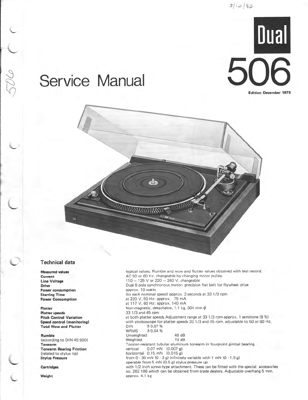
Dual CS 506 User manual
Dual 491 User manual
Dual DT 210 USB User manual
Dual DTJ 303 USB User manual
Dual HS 148 User manual
Dual 704 User manual
Dual PRP 5 User manual
Dual CS 430 User manual
Dual CS 400 User manual
Dual 1239 User manual
Dual 1019 User manual
Dual HS 31 User manual
Dual CS 628 User manual
Dual CS 731 Q User manual
Dual 1009 F User manual
Dual CS 714 Q User manual
Dual p 400 BN User manual
Dual DT250 User manual
Gemini
Gemini CDT-05 MKII product manual
Rotel
Rotel RP-820 owner's manual
Shuman
Shuman MC-250BT user manual
Stanton
Stanton STR8-150 owner's manual
Audio Technica
Audio Technica AT-LPW40WN user manual
Crosley
Crosley McQueen CR7011-GY instruction manual
auna
auna TT-Classic Plus instruction manual
COMO AUDIO
COMO AUDIO Turntable Analog user manual
REED
REED Muse3C user manual
AXIOMTEK
AXIOMTEK OPS883-H Series Quick installation guide
Pioneer
Pioneer PL-71 operating instructions
Vestax
Vestax PDX-a1 owner's manual
Denon
Denon DP-400 owner's manual
Audio-Techica
Audio-Techica AT-LP60XBT user manual
Goldring
Goldring G99 instruction manual
Acoustic Signature
Acoustic Signature Typhoon NEO instruction manual
Bryston
Bryston BLP-1 owner's manual
Sony
Sony CDX-3002 Installation