manuals.online logo
Brands
  1. Home
  2. •
  3. Brands
  4. •
  5. DUCATI Performance
  6. •
  7. Motorcycle Accessories
  8. •
  9. DUCATI Performance ISTR-1083/01 User manual

DUCATI Performance ISTR-1083/01 User manual

Symbols
The symbols used in this manual are aimed at making reading di-
rect and easy. The symbols are used either to draw the reader's


to these symbols as they are used to remind of technical principles
or safety measures which will not be repeated extensively. They
must therefore be considered as "reminders". Check with this page
in case of doubt about their meaning.

Failure to comply with these instructions may put you at risk and
lead to severe injury or death.

It indicates the possibility of damaging the motorcycle and/or its
components if the instructions are not followed.

It supplies useful information about the operation in progress.
References
 1
) represent the accessory to be installed and any assembly compo-
nents supplied with the kit.
 A) represent the original
components present on the motorcycle.
-
tion of travel (forward riding position).


The operations listed in the following pages must be carried out by
a specialised technician or by a Ducati authorised service centre.




The Workshop Manual of your motorcycle model is the documen-
tation required to assemble the Kit.





highway motor vehicle can expose you to chemicals including en-
gine exhaust, carbon monoxide, phthalates, and lead, which are

or other reproductive harm. To minimize exposure, avoid breath-
ing exhaust, do not idle the engine except as necessary, service
your vehicle in a well-ventilated area and wear gloves or wash your
hands frequently when servicing your vehicle. For more informa-
tion go to www.P65Warnings.ca.gov/passenger-vehicle.
 - 96781531CA


       

simboli, in quanto la loro funzione è quella di non dovere ripete-

  
ogni volta che sorgeranno dubbi sul loro significato.

-


-

Note
Fornisce utili informazioni sull’operazione in corso.
Riferimenti
 1)
rappresentano l’accessorio da installare e gli eventuali componenti
di montaggio forniti a kit.
      A) rappresentano i
componenti originali presenti sul motoveicolo.

del motociclo.


-
-
cati.

-

Note
Documentazione necessaria per eseguire il montaggio del Kit è il

Note
Nel caso fosse necessaria la sostituzione di un componente del kit
consultare la tavola ricambi allegata.
 - 96781531CA
1
ISTR - 1083 / 01


date, please refer to DCS (Dealer Communication System).

    
consultare il DCS (Dealer Communication System) per avere infor-
mazioni sempre aggiornate.
Pos. Denominazione Name
1Piastra Plate
2 Vite speciale M6x12 Special screw M6x12
3 Top Case Top Case
2

2
22
2
1
3


-
ditions. Adopt all necessary precautions to avoid damaging any


Place the plate (1) on the handle (A) by centring the fixing holes on


screws (2) to the specified torque.
.


        


operare.

Posizionare la piastra (1) sul maniglione (A), centrando i fori di
        
            
Impuntare le n. 4 viti (2). Serrare le n.4 viti (2) alla coppia indicata.
.

3
2
1
2
A
10 Nm ± 10% 10 Nm ± 10%

4
3A
3C 3E
3G
3G
3H
3F
3I
3H
3C 3C
C
C
3D
B
3C
3D
3B
W1
W3
W5
W7
W9 W10
W8
W6
W4
W2



Open the Top Case cover and remove the hinge by loosening the
two internal screws (3B) as shown in the figure (W2).
Working from the external side, remove the complete hinge (3C)
from its seat, taking care not to remove the release unit (3D) made

in the figure (W3).


blocks the two components together as indicated in the figure
(W4).
          
          


and the ball (3G) in the hinge seat as shown in the figure (W6).

keep the ball (3G) and spring (3F) in place as shown in the figure
(W7).

(3I). Tighten the screw as shown in the figure (W8).



unit (3D) into the relevant opening as shown in the figure (W9).
Secure the hinge from the inside of the Top Case (3) by tightening
the two screws (3B) previously removed. Close the cover, hook the
top end of the hinge (3C) and remove the key (C) as shown in the



rosso (3A) superiore per aprire la cerniera come indicato in figura
(W1).
Aprire il coperchio del Top Case e smontare la cerniera svitando le
n.2 viti (3B) interne come indicato in figura (W2).
Agendo dall'esterno, rimuovere dalla sua sede la cerniera completa

composto dal pulsante rosso, dal catenaccio interno e dalle molle
come indicato in figura (W3).


che blocca tra loro i due componenti come indicato in figura (W4).
Inserire nella sede ricavata sulla cerniera (3C), il blocco


come indicato in figura (W5).

la sfera (3G) nella sede della cerniera come indicato in figura (W6).
       

molla (3F) come indicato in figura (W7).

dotazione. Bloccare a fondo la vite come indicato in figura (W8).

           
        
contemporaneamente il gruppo di sgancio (3D) nella relativa

Fissare la cerniera dall'interno del Top Case (3), avvitando le due viti

         


5

motorcycle

         
  
slides (1A) of the plate (1).
             
locking tooth (1B) of the plate (1) into the opening (3N) at the
 
hearing the click of latch. Turn the key (C) to the closing position.


           
       



         
     

in posizione di chiusura. Sfilare la chiave.
6

6
1A
1
1B
3
C
3N
3
C

To open the Top Case (3) positioned on the motorcycle, turn the






the front slides.

Per aprire il Top Case (3) posizionato sul motoveicolo, occorre


ed aprire il coperchio.

         
(orizzontale) e spingere il pulsante inferiore (3M). Sollevare il Top



7
C
1B
3M
3L
3C
C
Note / Notes
1P/N商品名
2P/N商品名
3P/N商品名
4P/N商品名
5P/N商品名
ご注文商品
レース専用部品 ご注文書
    モデル名
    ご注文日
    販売日     年   月   日
1.
上記
ご
記入
の
上
、
弊社
アフターセールス
部
まで
FAX
してください
。
FAX
:
03
-
6692
-
1317
お客様ご記入欄
私は上記レース専用部品を下記車両に装着し、サーキット走行のみに
利用し、一般公道には利用しません。
販売店署名
販売店様へお願い
車台番号 ZDM
お客様署名
ドゥカティ正規ネットワーク店記入欄
お客様に上記レース専用部品を販売し、レース専用部品のご利用方法を
説明いたしました。
1.
上記
ご
記入
の
上
、
弊社
アフターセールス
部
まで
FAX
してください
。
FAX
:
03
-
6692
-
1317
2.
取
り
付
け
車両
1
台
に
1
枚
でご
使用
ください
。

9
2
7
2
5
4
8
2
7
2
5
5
4
8
2
5
4
8
2
4
8
2
3
66
1
ISTR - 1083 / 01
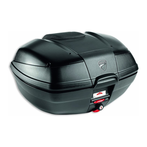
Kit Top Case / Top Case kit / Kit Top Case / Kit Top Case / Conjunto Top Case / Kit Top Case / トップケースキット - 96781531CA
Pos.  Denominazione Name Dénomination  Denominação Denominación 名称 Q.ty
1 Piastra inferiore Lower plate Plaque inférieure  Placa inferior Placa inferior ロアプレート 1
2 Boccola Bushing Bague Buchse Casquilho Casquillo ブッシュ 8
3 Piastra superiore  Plaque supérieure  Placa superior Placa superior アッパープレート 1
4 85211961B  Washer   Arruela Arandela ワッシャー 4
5 7791C251AA Vite speciale M6x12 Special screw
M6x12 Vis spéciale M6x12 Spezialschraube M6x12 Parafuso especial M6x12 Tornillo especial
M6x12
専用スクリュー
M6x12 4
6 Tampone in gomma  Tampon en
caoutchouc Gummistopfen Tampão de borracha Tapón de goma ラバーバッファー 4
7 Vite speciale M6x12 Special screw
M6x12 Vis spéciale M6x12 Spezialschraube M6x12 Parafuso especial M6x12 Tornillo especial
M6x12
専用スクリュー
M6x12 4
8 Gommino
antivibrante Vibration damper Plot antivibratoire Schwingungsdämpfergummi Borracha antivibrações Junta antivibrante 耐震ラバー 4
9 Top Case Top Case Top Case Topcase Top Case Top Case; トップケース 1


This manual suits for next models

1

Other DUCATI Performance Motorcycle Accessories manuals

DUCATI Performance 96781401A User manual

DUCATI Performance

DUCATI Performance 96781401A User manual

DUCATI Performance 96781310B User manual

DUCATI Performance

DUCATI Performance 96781310B User manual

DUCATI Performance 96781171B User manual

DUCATI Performance

DUCATI Performance 96781171B User manual

DUCATI Performance 96780655A User manual

DUCATI Performance

DUCATI Performance 96780655A User manual

DUCATI Performance 97480161A User manual

DUCATI Performance

DUCATI Performance 97480161A User manual

DUCATI Performance 96880921AA User manual

DUCATI Performance

DUCATI Performance 96880921AA User manual

DUCATI Performance 96981321AA User manual

DUCATI Performance

DUCATI Performance 96981321AA User manual

DUCATI Performance 96680702A User manual

DUCATI Performance

DUCATI Performance 96680702A User manual

DUCATI Performance Superbike 959 User manual

DUCATI Performance

DUCATI Performance Superbike 959 User manual

DUCATI Performance 96680702A User manual

DUCATI Performance

DUCATI Performance 96680702A User manual

DUCATI Performance 96680572A User manual

DUCATI Performance

DUCATI Performance 96680572A User manual

DUCATI Performance 96780551A User manual

DUCATI Performance

DUCATI Performance 96780551A User manual

DUCATI Performance 96681144AA User manual

DUCATI Performance

DUCATI Performance 96681144AA User manual

DUCATI Performance 96981341AA User manual

DUCATI Performance

DUCATI Performance 96981341AA User manual

DUCATI Performance Multistrada 1200 User manual

DUCATI Performance

DUCATI Performance Multistrada 1200 User manual

DUCATI Performance 97480171A User manual

DUCATI Performance

DUCATI Performance 97480171A User manual

DUCATI Performance 96880541AA User manual

DUCATI Performance

DUCATI Performance 96880541AA User manual

DUCATI Performance 96781421A User manual

DUCATI Performance

DUCATI Performance 96781421A User manual

DUCATI Performance 97380931B User manual

DUCATI Performance

DUCATI Performance 97380931B User manual

DUCATI Performance 97381951AA User manual

DUCATI Performance

DUCATI Performance 97381951AA User manual

DUCATI Performance 96681011AA User manual

DUCATI Performance

DUCATI Performance 96681011AA User manual

DUCATI Performance 96513603B User manual

DUCATI Performance

DUCATI Performance 96513603B User manual

DUCATI Performance 96780761B User manual

DUCATI Performance

DUCATI Performance 96780761B User manual

DUCATI Performance 97380182A User manual

DUCATI Performance

DUCATI Performance 97380182A User manual

Popular Motorcycle Accessories manuals by other brands

MSD Powersports Launch Master installation instructions

MSD Powersports

MSD Powersports Launch Master installation instructions

PZRacing A2-Tronic AP601 user manual

PZRacing

PZRacing A2-Tronic AP601 user manual

Artotic SUN9B user manual

Artotic

Artotic SUN9B user manual

Mustang 13322 manual

Mustang

Mustang 13322 manual

EME VR-ExtAdj Installation, Adjustment and Recommendations

EME

EME VR-ExtAdj Installation, Adjustment and Recommendations

Chicago Electric 47996 Assembly and operating instructions

Chicago Electric

Chicago Electric 47996 Assembly and operating instructions

Klein Tools 60145 instructions

Klein Tools

Klein Tools 60145 instructions

Two Brothers Racing 005-1840406V installation instructions

Two Brothers Racing

Two Brothers Racing 005-1840406V installation instructions

Wunderkind Custom 107045-F15 INSTALLATION MANUALS AND SAFETY INFORMATION

Wunderkind Custom

Wunderkind Custom 107045-F15 INSTALLATION MANUALS AND SAFETY INFORMATION

Thinkware sports M1 Quick start guide & warranty

Thinkware sports

Thinkware sports M1 Quick start guide & warranty

Suzuki 990D0-08J70 Series INSTRUCTIONS FOR MOUNTING & USE

Suzuki

Suzuki 990D0-08J70 Series INSTRUCTIONS FOR MOUNTING & USE

ScorpionExo EXO-200 Technical instructions

ScorpionExo

ScorpionExo EXO-200 Technical instructions

Topeak RIDECASE MOUNT HB quick start guide

Topeak

Topeak RIDECASE MOUNT HB quick start guide

R&G FI0089BK Fitting instructions

R&G

R&G FI0089BK Fitting instructions

Dakota Digital 2000 Series parts list

Dakota Digital

Dakota Digital 2000 Series parts list

hepco & becker 505992 00 01 Mounting instructions

hepco & becker

hepco & becker 505992 00 01 Mounting instructions
SRC K-VS11-01-01-SL Mounting instructions

SRC

SRC K-VS11-01-01-SL Mounting instructions

Arai Helmet RX-7 Corsair user manual

Arai Helmet

Arai Helmet RX-7 Corsair user manual

manuals.online logo
manuals.online logoBrands
  • About & Mission
  • Contact us
  • Privacy Policy
  • Terms and Conditions

Copyright 2025 Manuals.Online. All Rights Reserved.