manuals.online logo
Brands
  1. Home
  2. •
  3. Brands
  4. •
  5. DUCATI Performance
  6. •
  7. Motorcycle Accessories
  8. •
  9. DUCATI Performance 96781310B User manual

DUCATI Performance 96781310B User manual

Modelli di riferimento: / Reference Ducati Motorcycles:
I particolari con riferimento cerchiato rappresentano l’accessorio da installare e gli eventuali
componenti di montaggio.
Quelli non cerchiati si riferiscono ai componenti originali che devono essere riutilizzati.
Per una lettura rapida e razionale sono stati impiegati simboli che evidenziano situazioni di
massima attenzione, consigli pratici o semplici informazioni.
Tutte le indicazioni destro o sinistro si riferiscono al senso di marcia del motociclo.
Part nos. that are circled represent the accessory to be installed and possible relevant fittings.
Part nos. that are not circled refer to original parts to be re-used.
For easy and rational reading, this document uses graphic symbols for
highlighting situations in which maximum care is required, practical advice or simple information.
Any right- or left-hand indication refers to the vehicle direction of travel.
Attenzione / Warning
La non osservanza delle istruzioni riportate può creare una situazione di pericolo e causare
gravi lesioni personali e anche la morte. / Failure to follow these instructions might give raise to
a dangerous situation and provoke severe personal injuries or even death.
Importante / Caution
Indica la possibilità di arrecare danno al veicolo e/o ai suoi componenti se le istruzioni
riportate non vengono eseguite. / Failure to follow these instructions might cause damages to the
vehicle and/or its components.
Note / Note
Fornisce utili informazioni sull'operazione in corso. / Useful information on the procedure
being described.
Cod. ISTR - 355 Pag. - Page 1/10
Streetfighter
Kit antifurto / Anti-theft security kit - 96781310B
Kit telecomando antifurto / Antitheft system remote control kit - 96768909B
1 Centralina allarme
2 Cablaggio antifurto
3 Telecomando antifurto
4 Vite fissaggio centralina
5 Porta-led
6 Cover serbatoio porta-led
7 Guarnizione
8 Vite fissaggio cablaggio
1 Alarm control unit
2 Antitheft system wiring
3 Antitheft system remote control
4 Control unit retaining screw
5 LED-holder
6 LED-holder tank cover
7Seal
8 Wiring retaining screw
7
4
58
2
1
3
6
Cod. ISTR - 355Pag. - Page 2/10
Note
Read the instructions on the first
page carefully before proceeding.
Removing the original
components
Please refer to the workshop manual of the
bike you are working on, and remove the
following parts:
- Seat (W) (SECT. E 3).
- Tank cover (Z) (SECT.L 2).
- Inner (Y) and outer (X) LH air scoop
(SECT.L 7).
W
Z
X
Y
Note
Prima di iniziare l’operazione, leggere
attentamente le avvertenze riportate nella
prima pagina.
Smontaggio componenti
originali
Facendo riferimento al manuale officina
della moto in vostro possesso, eseguire i
seguenti smontaggi:
- Sella (W) (SEZ. E 3).
- Cover serbatoio (Z) (SEZ.L 2).
- Convogliatore aria sinistro esterno (X) e
interno (Y) (SEZ.L 7).
Cod. ISTR - 355 Pag. - Page 3/10
Fitting the anti-theft security kit
Warning
The motorcycle engine shall be off
and the bike shall be supported adequately
by means of a service stand.
Caution
Before fitting, make sure that all the
components are clean and in perfect
conditions. Take all the appropriate
measures to avoid damage to any of the
bike’s surfaces.
Warning
It is forbidden to fix the wires and the
system components with ties above or
close to heat sources (E.g.: exhaust
system, voltage regulator, etc.).
Fit seal (7) inside the special recess onto
wiring (2).
Connect plugs (2A) and (2B) of wiring (2) to
control unit (1).
Position wiring (2) head cap (2C) inside its
seat onto control unit (1).
Screw and tighten screws (8).
Position Control Unit assy (1) inside tail
guard. Loosen rear “RH side panel / tail
guard” retaining screw.
2
7
1
2A
2B
2
2C
1
2
8
1
Montaggio Kit Antifurto
Attenzione
Eseguire l'operazione con motore
spento. Sostenere adeguatamente il
motociclo, utilizzando un cavalletto
ausiliario.
Importante
Verificare, prima del montaggio, che
tutti i componenti risultino puliti e in
perfetto stato. Adottare tutte le precauzioni
necessarie per evitare di danneggiare le
superfici nelle vicinanze delle quali si opera.
Attenzione
È vietato fissare o fascettare i cavi
elettrici e i componenti dell'impianto sopra
o nelle immediate vicinanze di fonti di calore
(ES: Impianto di scarico, regolatore di
tensione, ecc.).
Inserire nell'apposito incavo sul cablaggio
(2) la guarnizione (7).
Collegare le spine (2A) e (2B) del cablaggio
(2) alla centralina (1).
Posizionare la chiusura (2C) del cablaggio (2)
in sede sulla centralina (1).
Avvitare e serrare le viti (8).
Posizionare il gruppo Centralina (1)
all'interno del codone. Svitare la vite di
fissaggio "fianchetto destro / codone"
posteriore.
Cod. ISTR - 355Pag. - Page 4/10
Start screw (4) inside its thread through RH
side panel and tail guard, then screw it onto
control unit (1) fin (1A). Tighten screw (4).
Position wiring (2) onto vehicle and lay it to
the front along bike main wiring (J).
Install led holder (5) onto cover (6).
Working from cover (6) lower side, install
led (2D) inside led holder (5).
4
1A
1
2
2
J
6
5
6
2D
5
Impuntare la vite (4) passando attraverso il
fianchetto destro, il codone e avvitarla
sull'aletta (1A) della centralina (1). Serrare la
vite (4).
Posizionare il cablaggio (2) sul veicolo e farlo
proseguire in corrispondenza del cablaggio
principale (J) della moto verso l'anteriore.
Inserire il porta-led (5) sul cover (6).
Dal lato inferiore del cover (6) inserire il led
(2D) nel porta-led (5).
Cod. ISTR - 355 Pag. - Page 5/10
Position cover (6) onto fuel tank sliding led
wiring underneath the tank.
Disconnect ignition lock plug (E) from
socket (D). Insert antitheft system wiring
plug (2A) into bike wiring socket (D) and
plug (E) into socket (2B).
Loosen the original screw (F) onto alternator
cover. Align anti-theft wiring eyelet (2C)
with alternator cover hole, and secure it in
place by screwing again and tightening
screw (F).
Tighten all loose fasteners.
Refit all the parts previously disassembled,
referring to your vehicle workshop manual.
Caution
Within the antitheft system kit you
are provided with no. 2 remote controls (3).
The antitheft system can handle maximum
no. 8 remote controls.
To replace any lost remote control or to add
more (up to 8 maximum) you can order the
remote control kit part no. 96768909B and
then match the antitheft system to the
remote controls following the procedure
indicated under “CHECKS“ in “STORING
NEW REMOTE CONTROLS”.
6
D
E
2A
2B
F
2C
3
Posizionare la cover (6) sul serbatoio
benzina inserendo il cablaggio del led al di
sotto del serbatoio stesso.
Scollegare tra di loro la presa (D) dalla spina
(E) di collegamento blocco chiave. Inserire
la spina (2A) del cablaggio antifurto alla
presa (D) cablaggio moto e la spina (E) nella
presa (2B).
Svitare la vite originale (F) sul coperchio
alternatore. Posizionare l'occhiello (2C) del
cablaggio antifurto in corrispondenza della
foratura sul coperchio alternatore e fissarlo
riavvitando e serrando la vite (F).
Serrare tutti gli elementi di fissaggio lasciati
lenti per esigenze di montaggio.
Rimontare tutti i componenti smontati
precedentemente facendo riferimento al
manuale officina della moto in vostro
possesso.
Importante
In dotazione al kit antifurto vengono
forniti n.2 telecomandi (3);
La capacità massima di gestione del
sistema antifurto è n.8 telecomandi.
Per sostituizione di telecomandi persi o
l’implementazione fino ad un massimo di 8
è possibile richiedendo il kit telecomando
cod. 96768909B e procedere al
riconoscimento da parte del sistema
antifurto eseguendo le operazioni indicate
nelle “VERIFICHE” al sottoparagrafo
“MEMORIZZAZIONE NUOVI
RADIOCOMANDI”.
Cod. ISTR - 355Pag. - Page 6/10
Checks
Press button (A) on remote control (3), to
enable antitheft system; make sure it
turned on. Should it not be on, check
indicated wiring connections and make sure
they are properly made.
Ensure that system operates correctly and
then fix the antitheft system wiring to the
frame using the original rubber ties for
securing the bike wiring or using the
standard plastic ties where no rubber tie is
preset.
Refit the seat as described in SECT. E 3.
Antitheft system operation
instructions
Arming the alarm system
Press “BUTTON A” of the remote control,
the arming will be confirmed by:
- 3 acoustic signals (beep)
- 3 blinks of the parking lights.
- Lighting of the LED on tank cover.
- Activation of the electric engine block.
Disarming the alarm system
Press “BUTTON A” of the remote control,
the disarming will be confirmed by:
- One acoustic signal (beep)
- A single long flash of the parking lights.
- Turning off of the LED on tank cover.
- Deactivation of the electric engine block.
- Alarm tripped warning, if any, (parking
lights and beep).
Warning
For security reasons the alarm can’t
be armed when the igntion key is in the
“ON” position.
Armed state
Once the arming phase is completed (lit
LED), the central unit is ready to signal any
theft attempt. The blinking of the LED
installed on tank cover signals the armed
state.
Siren alarm disabling
During the first 5 seconds after arming (LED
fixed on) you can press “BUTTON B” on the
remote control to disable the siren. Two
acoustic signals will warn you that siren was
disabled.
In this case the control unit shall indicate
any breaking attempt only by turning on and
flashing the parking lights.
B
A
3
Verifiche
Premere il pulsante (A), sul telecomando
(3), di accensione antifurto e assicurarsi che
l’impianto entri in funzione. Nel caso non
entri in funzione controllare tutti i
collegamenti elettrici citati e assicurarsi che
siano stati eseguiti a regola d’arte.
Constatata la funzionalità dell’impianto
procedere al fissaggio del cablaggio antifurto
al telaio utilizzando le fascette originali di
fissaggio cablaggio moto o utilizzando delle
fascette in plastica commerciati ove non
sono previste quelle originali.
Rimontare la sella come indicato alla SEZ. E
3.
Istruzioni di funzionamento
antifurto
Inserimento del sistema d'allarme
Premere il “TASTO A”del radiocomando,
l'inserimento sarà confermato da:
- 3 segnali acustici (beep)
- 3 lampeggi delle luci di posizione.
- Accensione del LED sul cover serbatoio.
- Attivazione del blocco elettrico del
motore.
Disinserimento del sistema d'allarme
Premere il “TASTO A“del radiocomando, il
disinserimento sarà confermato da:
- Un segnale acustico (beep)
- 1 lampeggio lungo delle luci di posizione.
- Spegnimento del LED sul cover
serbatoio.
- Disattivazione del blocco elettrico del
motore.
- Segnalazione eventuale di allarme
avvenuto (luci di posizione e bip).
Attenzione
Per motivi di sicurezza non potrete
inserire l’allarme con la chiave di accensione
in posizione “ON”.
Stato di allerta
Terminata la fase di inserimento (LED fisso)
la centrale è pronta a segnalare ogni
tentativo di furto. Lo stato di allerta è
segnalato dal lampeggio del LED installato
sul cover serbatoio.
Esclusione sirena
Durante i primi 5 secondi d'inserimento
(LED fisso) premendo il “TASTO B” del
radiocomando è possibile escludere il
funzionamento della sirena. Due segnali
acustici segnaleranno che il suono della
sirena è stato escluso.
In questo caso la centralina segnalerà
l'effrazione solamente con il lampeggio
delle luci di posizione.
Cod. ISTR - 355 Pag. - Page 7/10
Warning
When vehicle instrument panel is
switched on or if “BUTTON B” on remote
control is pressed (panic alarm), the siren is
enabled.
Alarm
In case of a lift attempt, ignition attempt,
removal of left fairing panel, the system will
emit an optical-acoustic signal (flashing of
the parking lights and sounding of the siren)
for 30 seconds.
To interrupt the signalling without disarming
the alarm, press “BUTTON B“of the remote
control.
To interrupt the signalling and disarm the
system, press “BUTTON A” of the remote
control.
Siren disabling for consecutive
alarms
If, when alarm is armed, the alarm sensors
detect an alarm cause for 3 times in a row,
upon the fourth alarm cause, the control
unit will disable the siren and signal the
alarm only by the flashing parking lights.
During this stage engine electrical block is
still active.
Warning
When vehicle instrument panel is
switched on or if “BUTTON B” on remote
control is pressed (panic alarm), the siren is
enabled.
Panic alarm
5 seconds after arming (LED flashing),
press “BUTTON B” of the remote control:
the central unit does a 4 second alarm cycle.
To interrupt the alarm cycle, press
“BUTTON B” again.
Shock sensor adjustment
The shock sensor is pre-set at our
laboratories so as to strike the best
compromise between alarm sensitivity and
as few false alarms as possible. Should it be
necessary to change sensitivity setting,
disable alarm and follow this procedure:
- Turn the key to ON.
- Within 5 seconds, press “BUTTON A”
TO INCREASE sensitivity.
Some beep sounds in INCREASING volume
will indicate that sensor sensitivity is being
increased.
If the highest sound is repeated, this
indicates that you reached sensor
MAXIMUM sensitivity setting
- or “BUTTON B” TO DECREASE
sensitivity.
B
A
Attenzione
Nel caso venga acceso il quadro del
veicolo o venga premuto il “TASTO B” del
radiocomando (allarme panico), il suono
della sirena viene ripristinato.
Allarme
Nel caso si verifichi un'effrazione, urto,
accensione del quadro, il sistema interverrà
con una segnalazione ottica-acustica
(lampeggio luci di posizione e suono della
sirena) della durata di 30 secondi.
Per interrompere la segnalazione senza
disinserire l'allarme, premere il “TASTO B”
del radiocomando.
Per interrompere la segnalazione e
disinserire il sistema premere il “TASTO A”
del radiocomando.
Limitazione sonora per allarmi
consecutivi
Se durante lo stato di allerta i sensori
dell'allarme rilevano per 3 volte consecutive
una causa di allarme, la quarta causa
d'allarme la centrale escluderà la propria
sirena segnalando l'allarme solo con il
lampeggio delle luci di posizione. Durante
questa fase è comunque attivo il blocco
elettrico del motore.
Attenzione
Nel caso venga acceso il quadro del
veicolo o venga premuto il “TASTO B” del
radiocomando (allarme panico), il suono
della sirena viene ripristinato.
Allarme panico
Trascorsi i 5 secondi dall'inserimento (LED
lampeggiante), premere il “TASTO B” del
radiocomando, la centrale esegue un ciclo
di allarme della durata di 4 secondi. Per
interrompere il ciclo di allarme premere
nuovamente il “TASTO B”.
Regolazione sensore urto
Il sensore ad urto è già pretarato presso i
nostri laboratori, in modo tale da avere un
buon compromesso tra sensibilità d'allarme
e prevenzione contro i falsi allarmi. Nel caso
fosse necessario cambiare la sensibilità
eseguire ad antifurto disinserito questa
procedura:
- Ruotare la chiave in posizione ON.
- Nei primi 5 secondi premere il “TASTO
A” PER AUMENTARE la sensibilità.
Una serie di beep in tonalità CRESCENTE
indica l'aumento della sensibilità del
sensore.
La ripetizione del suono più acuto indica che
è stata raggiunta la MAGGIORE sensibilità
del sensore
- oppure il "TASTO B" PER DIMINUIRE la
sensibilità.
Cod. ISTR - 355Pag. - Page 8/10
Some beep sounds in DECREASING
volume will indicate that sensor sensitivity
is being decreased.
Sensitivity decrease limit setting
corresponds to sensor disabling and this
condition is signalled by 3 consecutive beep
sounds.
During set-up, you can test sensor
sensitivity by hitting the vehicle.
Setup is completed by turning the key back
to OFF or after 6 seconds from when the
remote control buttons were last pressed.
In case of power failure, the control unit
restores sensitivity factory setting.
Alarm memory
If the control unit identifies one or more
alarm causes, they are signalled when
alarm is unarmed by means of a further
flashing of the parking lights and a number
of beep sounds equal to the number of
triggered alarms (max. 7).
Backup battery power
The antitheft system is equipped with
internal batteries that guarantee its
operation even when the power supply
cable connected to the vehicle's battery is
cut.
Remote controls
The remote controls are powered by
standard alkaline batteries, available on the
market. Remove the battery if a remote
control is expected not to be used for some
time, in order to avoid damaging due to
possible acid leaking off the batteries.
Remote controls shall not be subjected to
shocks nor submerged into any fluid. When
battery is getting flat you will find that
transmission range is progressively
decreasing. Change the battery in good
time or you could incur in the case where
alarm is armed and your remote control
battery is flat.
Changing the remote control
battery
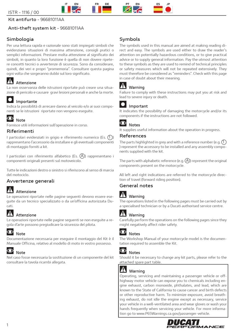
To change the remote control battery, open
remote control as shown, prising in the slot
using a screwdriver.
Change the flat battery with a new one type
CR2032, and fit correctly.
Warning
Before disposing of the remote
controls, remove the battery and dispose of
it according to the prevailing rules. Do not
release batteries in the environment.
B
A
Una serie di beep in tonalità
DECRESCENTE indica la diminuzione della
sensibilità del sensore.
La riduzione di sensibilità termina con
l'esclusione del sensore segnalato da 3
beep consecutivi.
Durante la fase di regolazione è possibile
testare la sensibilità del sensore colpendo il
veicolo.
La fase di regolazione termina ruotando la
chiave del veicolo in posizione OFF oppure
dopo 6 secondi dall'ultima pressione sui
tasti del radiocomando.
In caso di mancanza di alimentazione, la
centralina ripristina la sensibilità impostata
da fabbrica.
Memoria di allarme
Se la centrale registra una o più cause
d'allarme, esse vengono segnalate al
disinserimento tramite un'ulteriore
lampeggio degli indicatori di posizione e da
un numero di "beep" pari agli allarmi
avvenuti (max 7 segnalazioni).
Autoalimentazione
Il sistema antifurto è dotato di batterie
tampone che ne garantiscono il
funzionamento anche nel caso si tagli il cavo
che collega la batteria all'impianto elettrico
del veicolo.
Telecomandi
I telecomandi, per il proprio funzionamento,
utilizzano delle batterie alcaline facilmente
reperibili sul mercato. Se un telecomando
non dovesse venire utilizzato per parecchio
tempo, la batteria interna andrà rimossa per
prevenire danni causati dalla fuoriuscita di
acido dalla batteria stessa. I telecomandi
inoltre, non dovranno essere sottoposti ad
urti violenti e non dovranno subire
immersioni in alcun tipo di liquido. Una
progressiva diminuzione della portata di
trasmissione, indica che la batteria del
telecomando si sta scaricando. Sostituire la
batteria tempestivamente eviterà di
ritrovarsi con l'allarme inserito e il
telecomando inutilizzabile.
Sostituzione delle batterie
radiocomado
Per sostituire la batteria del radiocomando,
aprirlo come indicato in figura, facendo leva
con un giravite nella fessura.
Sostituire la batterie scarica con una nuova
del tipo CR2032 rispettandone la polarità.
Attenzione
Prima di gettare i radiocomandi non
più utilizzati, rimuovetene la batteria e
smaltitela secondo le normative vigenti.
Non disperdere la batteria nell'ambiente.
Cod. ISTR - 355Pag. - Page 9/10
Storing new remote controls
This procedure allows you to match new
remote controls or remote alarms to the
control unit (max. 8).
1 With system off (LED off) enter the
"SAFETY CODE" using the vehicle key
as detailed in the following paragraph.
2 After this, the vehicle parking lights will
flash quickly.
3 Enter "3" by means of the ignition key
(i.e. turn key ON and OFF 3 times in a
row).
4 The LED stays on for 10 seconds to
confirm procedure start.
5 During this time (while LED is on) press
“BUTTON A”on the new remote
control that is to be matched to the
alarm system or energize the remote
alarm. An acoustic signal and LED
switch-off will indicate that the storing
procedure is completed.
Using the safety code
It shall be used to disable the system when
remote controls are lost or not working and
the control is unit is still armed.
The code is always a 3-digit number (factory
setting is: 1-2-3) and shall be entered, with
control unit armed, using the vehicle
ignition key and following this procedure,
with alarm system armed:
1 Turn the key ON and OFF as many
times as the first digit (once in the
instance of the factory code)
While the code is being entered, the LED on
tank cover stays on and the siren turns on.
Allow for the LED to turn off.
2 Turn the key ON and OFF as many
times as the second digit (twice in the
instance of the factory code)
3 Allow for the LED to turn off.
4 Turn the key ON and OFF as many
times as the third digit (3 times in the
instance of the factory code)
If the operation is correct, the system will
unarm after the third digit is entered.
A
Memorizzazione nuovi
radiocomandi
La procedura permette di abbinare nuovi
radiocomandi o teleallarmi alla centralina
(max 8).
1 A sistema disinserito (LED spento)
comporre il “CODICE SEGRETO DI
SBLOCCO” attraverso la chiave del
veicolo vedi paragrafo seguente.
2 Al termine le luci di posizione del
veicolo lampeggeranno velocemente.
3 Comporre tramite la chiave di
accensione la cifra “3” (Accendere e
spegnere 3 volte il quadro della moto
consecutivamente).
4 Il LED si accende fisso per 10 secondi
confermando che la procedura è
avviata.
5 Durante questo tempo (LED acceso)
premere il “TASTO A” del nuovo
radiocomando da abbinare all'allarme o
eccitare il teleallarme. Un segnale
acustico e lo spegnimento del LED
dell'allarme segnalano che la
memorizzazione è terminata.
Uso del codice segreto di
sblocco
Va usato per disinserire il sistema quando i
radiocomandi non funzionano o vengono
smarriti e la centralina è rimasta inserita.
Il codice è sempre un numero di 3 cifre
(dalla fabbrica è: 1-2-3) e si compone, a
centralina inserita, con la chiave di
accensione del veicolo eseguendo questa
procedura ad allarme inserito:
1 Accendere e spegnere il quadro del
veicolo tante volte quanto è il valore
della prima cifra (1 volta nel caso di
codice di fabbrica)
Durante la composizione del codice
segreto, il LED sul cover serbatoio rimane
acceso e la sirena suona.
Attendere che il LED si spenga.
2 Accendere e spegnere il quadro del
veicolo tante volte quanto è il valore
della seconda cifra (2 volte nel caso di
codice di fabbrica)
3 Attendere che il LED si spenga.
4 Accendere e spegnere il quadro del
veicolo tante volte quanto è il valore
della terza cifra (3 volte nel caso di
codice di fabbrica)
Se l'operazione è corretta dopo la terza cifra
il sistema si disinserisce.
Cod. ISTR - 355Pag. - Page 10/10
Changing the safety code
This operation allows you to customise the
safety code and change the factory-set one
(1-2-3). Proceed as follows:
- Enter the SAFETY CODE using the key,
as described above.
- Allow for the parking lights to flash 4
times to confirm that the entered safety
code is correct.
- Turn the key ON and OFF as many times
as the FIRST DIGIT to be changed. While
the code is being entered, the LED on
instrument panel stays on.
- Allow for the LED on instrument panel to
turn off.
- Turn the key ON and OFF as many times
as the SECOND DIGIT to be changed.
- Allow for the LED on instrument panel to
turn off.
- Turn the key ON and OFF as many times
as the THIRD DIGIT to be changed. If the
operation is correct, the system will
issue some beep sounds after the THIRD
DIGIT is entered and the LED will flash to
confirm that the new code was stored
and has superseded the old code. If the
procedure is not correct, the alarm
system will “beep” once and the safety
code will remain unchanged.
Take note of your new safety code here:
Alarm system maintenance
Washing the vehicle
When washing the vehicle with high-
pressure devices (water-jet cleaner or
similar devices) take care to protect the
alarm system before starting. When
washing all vehicle parts or if you are not
sure whether you are correctly shielding the
alarm system, remove it from the vehicle.
Warranty is null and void in case of water
seepage due to the use of a water-jet
cleaner.
General maintenance
All repair operations of the alarm system
shall be carried out by specialized staff.
Unauthorised personnel tampering with the
alarm system could compromise the device
reliability as well as the vehicle safety.
IL NUOVO CODICE DI SBLOCCO È
Cambio del codice segreto di
sblocco
Questa operazione permette di
personalizzare il codice segreto di sblocco
da quello di fabbrica (1-2-3) a quello
desiderato seguendo questa procedura:
- Attraverso la chiave quadro comporre il
CODICE SEGRETO come descritto nel
paragrafo precedente.
- Attendere 4 lampeggi delle luci di
posizione che confermano la correttezza
del vecchio codice di sblocco.
- Accendere e spegnere il quadro del veicolo
tante volte quanto è il valore della PRIMA
CIFRA che s'intende modificare. Durante
la composizione del codice segreto, il LED
sul cruscotto rimane acceso.
- Attendere che il LED sul cruscotto si
spenga.
- Accendere e spegnere il quadro del
veicolo tante volte quanto è il valore della
SECONDA CIFRA che s'intende
modificare.
- Attendere che il LED sul cruscotto si
spenga.
- Accendere e spegnere il quadro del
veicolo tante volte quanto è il valore della
TERZA CIFRA che s'intende modificare.
Se l'operazione è corretta dopo la TERZA
CIFRA l'allarme emetterà una serie di
"beep" e farà lampeggiare il LED per
confermare che il nuovo codice di sblocco
è stato memorizzato ed ha sostituito il
precedente. Se la procedura non è
corretta, l'allarme, emetterà un “beep” e il
codice di sblocco non risulterà cambiato.
Annotare in questo spazio il vostro nuovo
codice di sblocco:
Manutenzione allarme
Lavaggio del veicolo
Nel caso in cui il veicolo dovesse venire
lavato con dispositivi ad alta pressione
(idrogetto o simili) è necessario proteggere
l'allarme prima di iniziare il lavaggio. Se non si
è sicuri di proteggere l'allarme a sufficienza o
se il lavaggio deve essere fatto in tutte le
parti del veicolo, l'allarme andrà rimosso dalla
propria sede. Nel caso si verifichino
infiltrazioni d'acqua causate dell'utilizzo
dell'idrogetto, la garanzia decadrà
Manutenzione generale
Tutte le operazioni di riparazione
dell'allarme devono essere eseguite da
personale specializzato. Le manomissioni
dell'allarme da parte di personale non
autorizzato può compromettere l'affidabilità
del dispositivo e la sicurezza in ordine di
marcia del veicolo.
IL NUOVO CODICE DI SBLOCCO È
1P/N商品名
2P/N商品名
3P/N商品名
4P/N商品名
5P/N商品名
ご注文商品
レース専用部品 ご注文書
DUCATI PERFORMANCE
accessories
    モデル名
    ご注文日
    販売日     年   月   日
1.
上記
ご
記入
の
上
、
弊社
アフターセールス
部
まで
FAX
してください
。
FAX
:
03
-
6692
-
1317
お客様ご記入欄
私は上記レース専用部品を下記車両に装着し、サーキット走行のみに
利用し、一般公道には利用しません。
販売店署名
販売店様へお願い
車台番号 ZDM
お客様署名
ドゥカティ正規ネットワーク店記入欄
お客様に上記レース専用部品を販売し、レース専用部品のご利用方法を
説明いたしました。
1.
上記
ご
記入
の
上
、
弊社
アフターセールス
部
まで
FAX
してください
。
FAX
:
03
-
6692
-
1317
2.
取
り
付
け
車両
1
台
に
1
枚
でご
使用
ください
。

This manual suits for next models

1

Other DUCATI Performance Motorcycle Accessories manuals

DUCATI Performance 96981341AA User manual

DUCATI Performance

DUCATI Performance 96981341AA User manual

DUCATI Performance 97480161A User manual

DUCATI Performance

DUCATI Performance 97480161A User manual

DUCATI Performance Superbike 959 User manual

DUCATI Performance

DUCATI Performance Superbike 959 User manual

DUCATI Performance 97180791AA User manual

DUCATI Performance

DUCATI Performance 97180791AA User manual

DUCATI Performance 96781421A User manual

DUCATI Performance

DUCATI Performance 96781421A User manual

DUCATI Performance 96880921AA User manual

DUCATI Performance

DUCATI Performance 96880921AA User manual

DUCATI Performance 96981461AA User manual

DUCATI Performance

DUCATI Performance 96981461AA User manual

DUCATI Performance 96780231C User manual

DUCATI Performance

DUCATI Performance 96780231C User manual

DUCATI Performance 97480211AA User manual

DUCATI Performance

DUCATI Performance 97480211AA User manual

DUCATI Performance 96981321AA User manual

DUCATI Performance

DUCATI Performance 96981321AA User manual

DUCATI Performance 97380931B User manual

DUCATI Performance

DUCATI Performance 97380931B User manual

DUCATI Performance 96781401A User manual

DUCATI Performance

DUCATI Performance 96781401A User manual

DUCATI Performance 96780551A User manual

DUCATI Performance

DUCATI Performance 96780551A User manual

DUCATI Performance 96680572A User manual

DUCATI Performance

DUCATI Performance 96680572A User manual

DUCATI Performance ISTR-1083/01 User manual

DUCATI Performance

DUCATI Performance ISTR-1083/01 User manual

DUCATI Performance 96781171B User manual

DUCATI Performance

DUCATI Performance 96781171B User manual

DUCATI Performance 96780861C User manual

DUCATI Performance

DUCATI Performance 96780861C User manual

DUCATI Performance 96780231C User manual

DUCATI Performance

DUCATI Performance 96780231C User manual

DUCATI Performance 96981261AA User manual

DUCATI Performance

DUCATI Performance 96981261AA User manual

DUCATI Performance 96680702A User manual

DUCATI Performance

DUCATI Performance 96680702A User manual

DUCATI Performance 96780761B User manual

DUCATI Performance

DUCATI Performance 96780761B User manual

DUCATI Performance 96880541AA User manual

DUCATI Performance

DUCATI Performance 96880541AA User manual

DUCATI Performance 96781491AA User manual

DUCATI Performance

DUCATI Performance 96781491AA User manual

DUCATI Performance 96780851A User manual

DUCATI Performance

DUCATI Performance 96780851A User manual

Popular Motorcycle Accessories manuals by other brands

R&G AB0026BK Fitting instructions

R&G

R&G AB0026BK Fitting instructions

BITEHARDER HAPC12V instructions

BITEHARDER

BITEHARDER HAPC12V instructions

KTM 00029920000EB Information

KTM

KTM 00029920000EB Information

iB 02.20500 manual

iB

iB 02.20500 manual

Rivco VCC094 quick start guide

Rivco

Rivco VCC094 quick start guide

thousand TRAVELER LIGHT owner's manual

thousand

thousand TRAVELER LIGHT owner's manual

rizoma Spirit RS user manual

rizoma

rizoma Spirit RS user manual

KTM Power Parts 69105283100 Information

KTM Power Parts

KTM Power Parts 69105283100 Information

ACEBIKES SteadyStand Multifixed quick start guide

ACEBIKES

ACEBIKES SteadyStand Multifixed quick start guide

Malossi Force Master 2 manual

Malossi

Malossi Force Master 2 manual

R&G FI0135BK Fitting instructions

R&G

R&G FI0135BK Fitting instructions

hepco & becker LEGACY 6357530 00 01 quick start guide

hepco & becker

hepco & becker LEGACY 6357530 00 01 quick start guide

hepco & becker 5017574 00 01 manual

hepco & becker

hepco & becker 5017574 00 01 manual

AKE Bluetooth helmet set 101 Operating and installation instructions

AKE

AKE Bluetooth helmet set 101 Operating and installation instructions

IBEX 10006887-6902 Mounting instruction

IBEX

IBEX 10006887-6902 Mounting instruction

BGS technic 8867 instruction manual

BGS technic

BGS technic 8867 instruction manual

Kappa K'FORCE MONOKEY KFR580A owner's manual

Kappa

Kappa K'FORCE MONOKEY KFR580A owner's manual

Soehnle HEATING PAD operating instructions

Soehnle

Soehnle HEATING PAD operating instructions

manuals.online logo
manuals.online logoBrands
  • About & Mission
  • Contact us
  • Privacy Policy
  • Terms and Conditions

Copyright 2025 Manuals.Online. All Rights Reserved.