manuals.online logo
Brands
  1. Home
  2. •
  3. Brands
  4. •
  5. Dynojet
  6. •
  7. Motorcycle Accessories
  8. •
  9. Dynojet Power Commander FC User manual

Dynojet Power Commander FC User manual

2008-2014 Kawasaki Brute Force 750 - 1IFC17019.01 www.powercommander.com
Installation Instructions
PLEASE READ ALL DIRECTIONS BEFORE STARTING INSTALLATION
THE IGNITION MUST BE TURNED
OFF BEFORE INSTALLATION!
YOU CAN ALSO DOWNLOAD THE PCFC
CONTROL CENTER SOFTWARE AND
LATEST MAPS FROM OUR WEB SITE AT:
www.powercommander.com
2191 Mendenhall Drive North Las Vegas, NV 89081 (800) 992-4993 www.powercommander.com
2008-2014 Kawasaki
2008-2014 Kawasaki
Brute Force 750
Brute Force 750
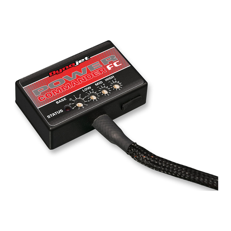
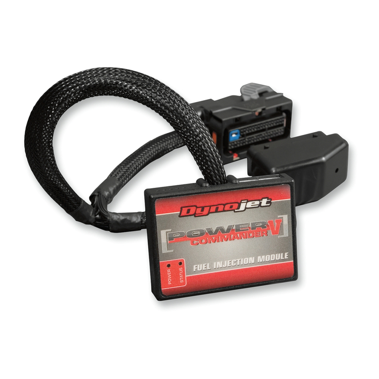
1 Power Commander FC
1 USB Cable
1 Installation Guide
2 Dynojet Decals
2 Velcro
1 Alcohol swab
Parts List
Parts List
IFC17019.01 www.powercommander.com 2008-2014 Kawasaki Brute Force 750 - 2
SELECTING THE MAP POSITION
The Dynojet Power Commander Fuel Controller (PCFC) comes loaded with up to ten
maps. Using a #1 Phillips screwdriver, turn the map select dial to toggle between the
loaded maps. Refer to the map position table for the maps included in your PCFC.
USING THE RPM RANGE DIALS
The Low, Mid, and High RPM Dials refer to the RPM range, in thirds, of your vehicle.
Each dial allows +/- 10% fuel adjustment on top of what fuel changes are done in the
map. With the dial facing straight up, there is no additional fuel change.
For example, if your vehicle revs to 6000 RPM:
• The low RPM dial will adjust 0-2000 RPM
• The mid RPM dial will adjust 2001-4000 RPM
• The high RPM dial will adjust 4001-6000 RPM
USING PCFC CONTROL CENTER
Take your tuning to the next level with the PCFC Control Center software.
1 Using your web browser, navigate to www.powercommander.com.
2 Click Enter Race Ready.
3 Click Downloads.
4 Click Access Downloads for Power Commander FC.
5 Click the PCFC software Download button.
6 Open the zip folder.
7 Double-click the install file and follow the on-screen instructions to install the PCFC
Control Center software. The PCFC Control Center software and maps will be
stored in C:\Program Files\PCFC Control Center.
8 Return to the Downloads or Home page where you can enter the make, model, and
year of your bike to check for and download additional maps.
LOADING ADDITIONAL MAPS
1 Connect the USB cable from the computer to the PCFC. Verify the cable is fully
seated in the PCFC.
2 Run the Control Center software by double-clicking the program icon installed on
your desktop or on your start menu.
3 Click Open Map File and select a map file.
4 Click Send Map. You can send the map to any of the ten map positions.
ALTERING MAPS USING SOFTWARE
The values in the map represent a percentage of fuel change over stock. A value of 10 in
the map indicates at that throttle position and RPM range the vehicle will be 10% richer
than stock. If the value is -10, then it would be 10% leaner than stock. You have the
ability to fine tune your fuel curve by altering these values. The Control Center software
allows a value of +250 to -100 in each cell.
USB Port
HIGH RPM Dial
MID RPM Dial
LOW RPM Dial
MAP Select
STATUS Light
Position Note
Position 1
2008-2011 Kawasaki Brute Force 750
Stock exhaust
Stock air filter
Position 2
2012-2014 Kawasaki Brute Force 750
Stock exhaust
Stock air filter
IFC17019.01 www.powercommander.com 2008-2014 Kawasaki Brute Force 750 - 3
2008-2011 Kawasaki Brute Force 750
Use the following instructions for 2008-2011 models.
1 Remove the seat.
2 Remove the right hand side cover as shown in Figure A.
3 Locate the black 6-pin connector that comes from the throttle bodies.
This connector is located on the right hand side of the Quad near the upper
frame rail.
4 Unplug this connector as shown in Figure B.
5 Attach the connectors from the PCFC harness to the stock wiring harness and
throttle body harness as shown in Figure C.
FIG.A
FIG.B
FIG.C
IFC17019.01 www.powercommander.com 2008-2014 Kawasaki Brute Force 750 - 4
6 Attach the ground wire from the PCFC harness to the negative side of the
battery as shown in Figure D.
7 Using the supplied velcro, secure the PCFC to the top of the ECU as shown in
Figure E.
Make sure to clean both surfaces before attaching with the alcohol swab.
8 Reinstall side cover and seat.
2012-2014 Kawasaki Brute Force 750
Use the following instructions for the 2012-2014 models.
1 Remove the seat.
2 Remove the right hand side cover, and the cover in front of the steering stem
that holds the accessory outlet as shown in Figure F.
The shifter knob and key switch will need to be removed to pull the right side
cover off.
FIG.D
FIG.E
FIG.F
harness
ground
IFC17019.01 www.powercommander.com 2008-2014 Kawasaki Brute Force 750 - 5
3 Using the supplied velcro, secure the PCFC to the tray under the seat as
shown in Figure G.
Make sure to clean both surfaces with the alcohol swab before attaching.
FIG.G
4 Route the PCFC harness under the plastic tray and down the right hand side
of the ATV, following the stock wiring harness as shown in Figure H.
This wire routing will be much easier with the clutch snorkel and the two bolts
at the front of the tray under the seat removed.
5 Locate the 6-pin BLACK connector on the front head, that comes from the
throttle bodies as shown in Figure I.
This connector is behind the coolant hose as shown in Figure I.
6 Unplug this connector.
FIG.H
FIG.I
IFC17019.01 www.powercommander.com 2008-2014 Kawasaki Brute Force 750 - 6
7 Attach the connectors from the PCFC wiring harness to the stock wiring
harness and throttle body harness as shown in Figure J.
FIG.J
8 Attach the ground wire from the PCFC harness to the ground bolt on the
shifter bracket as shown in Figure K.
9 Secure the PCFC harness clear of any hot or moving parts.
10 Reinstall the clutch snorkel if removed.
11 Reinstall the plastic covers, shifter knob, key switch, and seat.
FIG.K

Other Dynojet Motorcycle Accessories manuals

Dynojet POWER COMMANDER FC User manual

Dynojet

Dynojet POWER COMMANDER FC User manual

Dynojet Power commander V User manual

Dynojet

Dynojet Power commander V User manual

Dynojet Power commander V User manual

Dynojet

Dynojet Power commander V User manual

Dynojet Power commander V User manual

Dynojet

Dynojet Power commander V User manual

Dynojet Power Commander V 23-010 User manual

Dynojet

Dynojet Power Commander V 23-010 User manual

Dynojet Power Commander III USB Ignition Module User manual

Dynojet

Dynojet Power Commander III USB Ignition Module User manual

Dynojet POWER VISION 4 User manual

Dynojet

Dynojet POWER VISION 4 User manual

Dynojet Power Comander V User manual

Dynojet

Dynojet Power Comander V User manual

Dynojet Power commander V User manual

Dynojet

Dynojet Power commander V User manual

Dynojet Power commander V User manual

Dynojet

Dynojet Power commander V User manual

Dynojet Power commander V User manual

Dynojet

Dynojet Power commander V User manual

Dynojet Power commander V User manual

Dynojet

Dynojet Power commander V User manual

Dynojet POWER COMMANDER III User manual

Dynojet

Dynojet POWER COMMANDER III User manual

Dynojet Power Commander III User manual

Dynojet

Dynojet Power Commander III User manual

Dynojet Power commander V User manual

Dynojet

Dynojet Power commander V User manual

Dynojet POWER COMMANDER FC User manual

Dynojet

Dynojet POWER COMMANDER FC User manual

Dynojet Power commander V User manual

Dynojet

Dynojet Power commander V User manual

Dynojet POWER COMMANDER FC User manual

Dynojet

Dynojet POWER COMMANDER FC User manual

Dynojet Power Commander III User manual

Dynojet

Dynojet Power Commander III User manual

Dynojet Power commander V User manual

Dynojet

Dynojet Power commander V User manual

Dynojet Power commander V User manual

Dynojet

Dynojet Power commander V User manual

Dynojet Power commander III User manual

Dynojet

Dynojet Power commander III User manual

Dynojet Power commander V User manual

Dynojet

Dynojet Power commander V User manual

Dynojet Power Commander 3 User manual

Dynojet

Dynojet Power Commander 3 User manual

Popular Motorcycle Accessories manuals by other brands

R&G FI0074BK Fitting instructions

R&G

R&G FI0074BK Fitting instructions

PUIG 9253 manual

PUIG

PUIG 9253 manual

AVT Ninja 650 NI install guide

AVT

AVT Ninja 650 NI install guide

hepco & becker 6537544 00 01 installation instructions

hepco & becker

hepco & becker 6537544 00 01 installation instructions

MSA F2 X-TREM operating manual

MSA

MSA F2 X-TREM operating manual

Voigt MT V2926 Mounting instruction

Voigt

Voigt MT V2926 Mounting instruction

Pandora Mini Moto User and installation manual

Pandora

Pandora Mini Moto User and installation manual

Paaschburg & Wunderlich HIGHSIDER CONERO Instruction and installation manual

Paaschburg & Wunderlich

Paaschburg & Wunderlich HIGHSIDER CONERO Instruction and installation manual

SIGNIFY EA2306 instruction manual

SIGNIFY

SIGNIFY EA2306 instruction manual

MadStad Engineering Robo Knob manual

MadStad Engineering

MadStad Engineering Robo Knob manual

MRA 4025066168767 Mounting instructions

MRA

MRA 4025066168767 Mounting instructions

KTM Power Parts 7503002605049 Information

KTM Power Parts

KTM Power Parts 7503002605049 Information

Nolan m5 User instructions and safety

Nolan

Nolan m5 User instructions and safety

Suzuki 990D0-17K35-000 installation instructions

Suzuki

Suzuki 990D0-17K35-000 installation instructions

ConforTeck DUO user manual

ConforTeck

ConforTeck DUO user manual

Nolan N71 Safety and instructions for use

Nolan

Nolan N71 Safety and instructions for use

LSL 150A022 FITTING INSTRUCTION

LSL

LSL 150A022 FITTING INSTRUCTION

hepco & becker 42229522 00 01 manual

hepco & becker

hepco & becker 42229522 00 01 manual

manuals.online logo
manuals.online logoBrands
  • About & Mission
  • Contact us
  • Privacy Policy
  • Terms and Conditions

Copyright 2025 Manuals.Online. All Rights Reserved.