Egro NEXT Top Milk User manual

NEXT
Technical Manual
ENGLISH

Egro NEXT
Technical Manual 2 Rev: AA / 09/2018
Content
1. Introduction.............................................................................................................................................. 4
2. Technical data........................................................................................................................................... 4
2.1. Type label.......................................................................................................................................... 4
2.2. Outlet................................................................................................................................................ 5
3. Installation................................................................................................................................................ 6
3.1. Electrical connections........................................................................................................................ 6
3.1.1. Change power settings............................................................................................................... 6
4. Service .......................................................................................................................................................7
4.1. Service Document ..............................................................................................................................7
4.2. Preventive Maintenance.....................................................................................................................7
4.2.1. Service interval ...........................................................................................................................7
4.2.2. Maintenance ..............................................................................................................................7
4.2.3. Lubricants...................................................................................................................................7
4.2.4. Service kits................................................................................................................................. 8
4.3. Grinder.............................................................................................................................................. 8
4.3.1. Change Grinder burrs................................................................................................................. 8
4.3.2. SAG –Self adjusting Grinder....................................................................................................... 8
4.4. Brewing unit...................................................................................................................................... 9
4.4.1. Remove the brewing unit ........................................................................................................... 9
4.4.2. Remove the spindle motor ......................................................................................................... 9
4.4.3. Brewing units............................................................................................................................. 9
4.4.4. Calibrating the brewing unit....................................................................................................... 9
4.5. Outlet............................................................................................................................................... 10
4.5.1. Manual outlet...........................................................................................................................10
4.5.2. Automatic spout AS .................................................................................................................. 10
4.6. Milk system.......................................................................................................................................11
4.6.1. Default values............................................................................................................................11
4.6.2. Milk temperature.......................................................................................................................11
4.6.3. Foam structure ..........................................................................................................................11
4.6.4. Correction time ..........................................................................................................................11
4.6.5. Change to pressure sensor ........................................................................................................ 12
4.6.6. Milk level calibration................................................................................................................. 12
4.6.7. Configurations Milk system....................................................................................................... 14
4.6.8. Cold Milk Foam CMF ................................................................................................................. 15
4.7. Fridge NEXT...................................................................................................................................... 16
4.7.1. Temperature adjustment .......................................................................................................... 16
4.7.2. Temperature offset ................................................................................................................... 16
4.7.3. Change temperature unit.......................................................................................................... 16
4.7.4. Remove milk pumps.................................................................................................................. 17
4.8. Under counter installation................................................................................................................ 17
4.9. Fridge FUM.......................................................................................................................................18
4.9.1. Temperature adjustment .......................................................................................................... 18
4.9.2. Remove milk pumps.................................................................................................................. 18
4.10. Powder Module................................................................................................................................ 19
4.10.1. Powder hopper ......................................................................................................................... 19
4.11. Diagrams, Fuses and Print Boards.................................................................................................... 20

Egro NEXT
Technical Manual 3 Rev: AA / 09/2018
5. Software .................................................................................................................................................. 21
5.1. Use of USB........................................................................................................................................ 21
5.2. Software components and versions.................................................................................................. 21
5.3. Filenames......................................................................................................................................... 21
5.4. Software update............................................................................................................................... 21
5.4.1. Control Board ........................................................................................................................... 21
5.4.2. Display /Android OS.................................................................................................................. 21
5.4.3. EgroTech and Egro UI................................................................................................................ 21
5.4.4. Recovery...................................................................................................................................22
5.4.5. Exchange of Touchscreen..........................................................................................................22
5.5. Pictures and videos ..........................................................................................................................22
5.5.1. Pictures ....................................................................................................................................22
5.5.2. Video........................................................................................................................................22
5.6. Display .............................................................................................................................................23
5.6.1. Clean the display.......................................................................................................................23
5.6.2. Lifetime ....................................................................................................................................23
5.7. Backup .............................................................................................................................................23
5.8. Technician Menu............................................................................................................................. 24
Product setup ..........................................................................................................................................25
Machine setup .........................................................................................................................................27
Date + Time............................................................................................................................................. 29
Cleanings settings ................................................................................................................................... 29
Counters ................................................................................................................................................ 30
Diagnostic ................................................................................................................................................32
6. Fault finding.............................................................................................................................................35
6.1. List of errors.....................................................................................................................................35
6.2. List of warnings ............................................................................................................................... 36
Document history
Date
Author
Revision
Changes
27.08.2018
Veith
--
First release
20.09.2019
Veith
AA
Complete rework –all chapters approved
Egro NEXT
Technical Manual 4 Rev: AA / 09/2018
1. Introduction
This manual gives additional information for the Egro NEXT.
It contains topics, which are not in the installation manual delivered with the machine or in the user
manual. This manual will be updated on a regularly base.
Please check yourself on www.ranciliogroup.com/Support
The manuals of Egro NEXT are available on the display and for download on our homepage
www.ranciliogroup.com
Further documentation, like document set (electric and hydraulic diagrams), software tree et al. can be
found in the restricted area of our download area.
2. Technical data
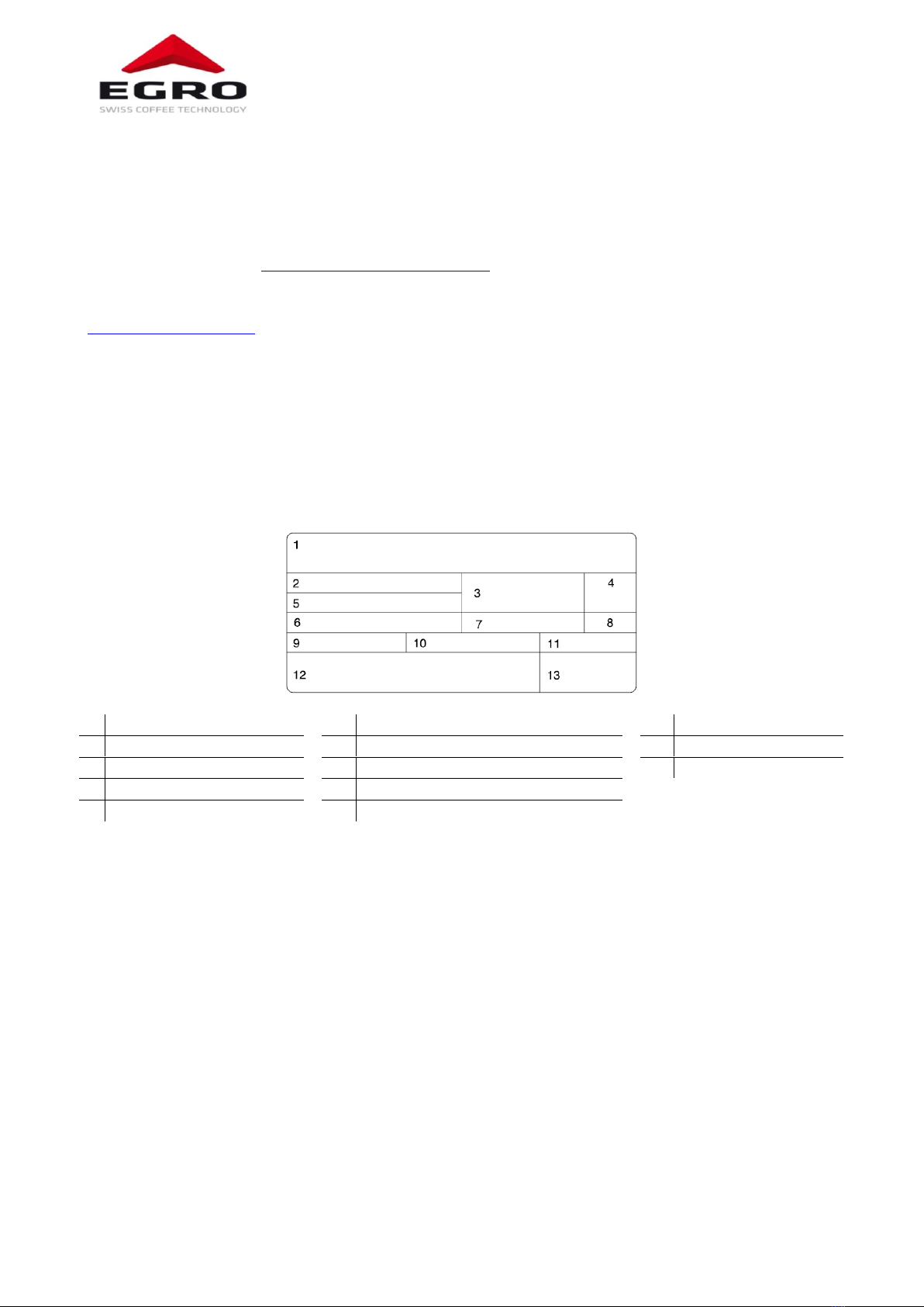
2.1. Type label
The type label is in the machine. Take out the ground drawer and it is visible on the left sidewall.
1
Manufacturer
6
Pin
11
Frequenc
2
Model and version
7
Total absorption
12
Conformity marks
3
Voltage
8
Motor power
13
Date of manufacture
4
EC Conformity mark
9
Max. boiler/static pressure
5
Serial number
10
Heating element power

Egro NEXT
Technical Manual 5 Rev: AA / 09/2018
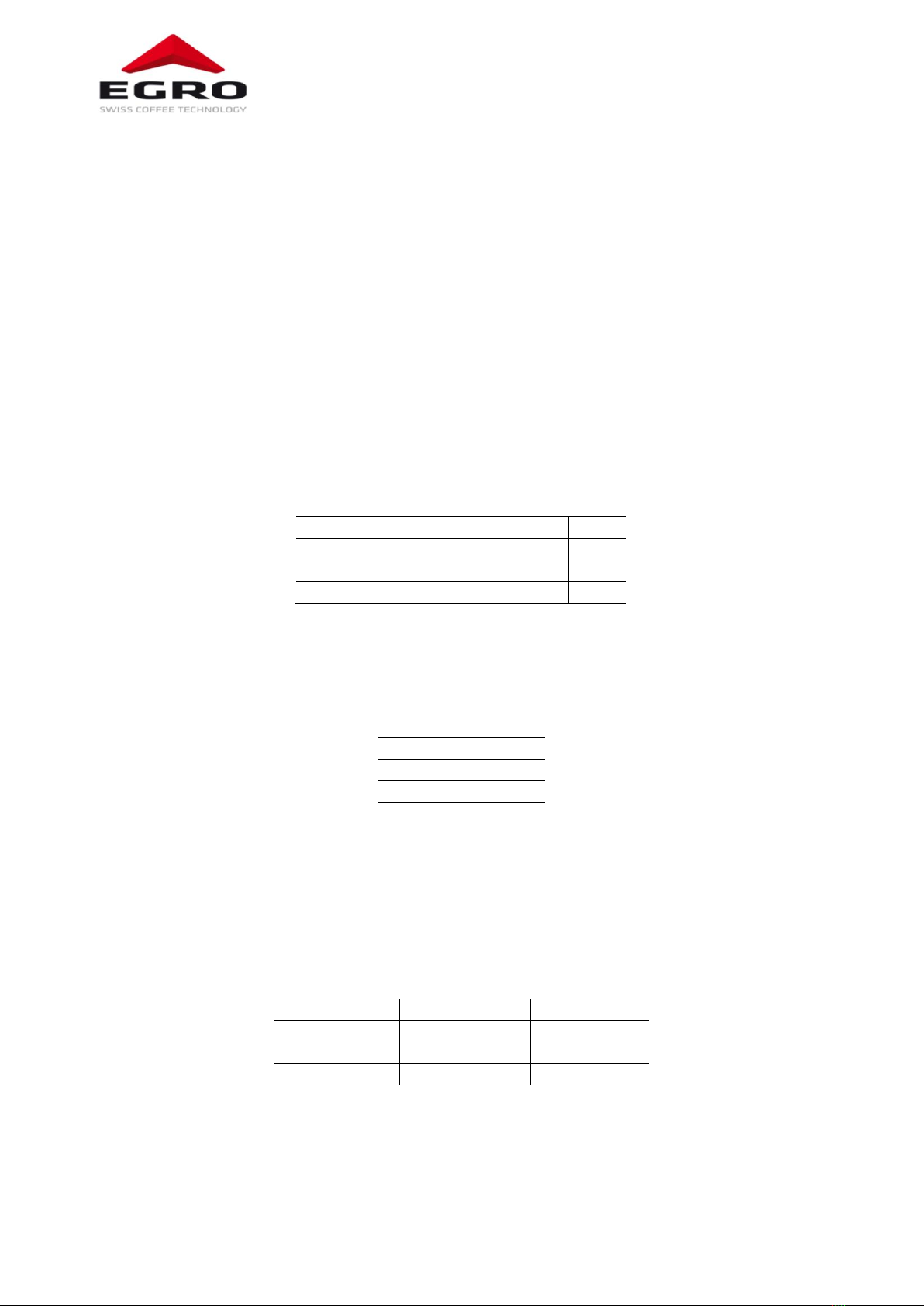
2.2. Outlet
1
Coffee
2
Hot Water
3
Milk/Milk foam
4
Powder product
5
Cold Milk Foam (CMF)
1
4
4
3
3
2
1
3
2
5
5
5

Egro NEXT
Technical Manual 6 Rev: AA / 09/2018
3. Installation
3.1. Electrical connections
The machines are delivered according to the information on the type label, but they offer different
electrical connections.
Power supply
Power rating
Identification
“Reduced Power”
220-240V 3~, 50/60Hz
5.5 kW
2P
OFF
220-240V 3~, 50/60Hz
6.0 kW
2P
OFF
380-415V 2N~, 50/60Hz
5.5 kW
2P
OFF
380-415V 2N~, 50/60Hz
6.0 kW
2P
OFF
220-240V 1N~ 50/60Hz
5.5 kW
1P
OFF
220-240V 1N~ 50/60Hz
6.0 kW
1P
OFF
220-240V 1N~ 50/60Hz
3.1 kW
LP
ON
220-240V 1N~ 50/60Hz
3.6 kW
LP
ON
208/240 V2ph~, 60Hz
5/6 kW
-
OFF
3.1.1. Change power settings
The power settings can be changed depending on the available power supply. The electrical diagram and
the installation manual show the different ways to connect the machine.
When connecting the machine to 220-240V 1N~ 50/60Hz with 16A fuse the parameter “Machine
setup/Boiler/Reduced Power” in the EgroTech App has to be set to “ON”.

Egro NEXT
Technical Manual 7 Rev: AA / 09/2018
4. Service
4.1. Service Document
The service document for information of maintenance done, will be delivered with every machine. It has
space for breakdowns, which should be noted down by the service technician.
4.2. Preventive Maintenance
Preventive maintenance ensures a continuous quality of products and reduces unscheduled breakdowns.
During preventive maintenance service will be done and necessary spare parts will be exchanged.
The base for preventing maintenance are “Service kits”with all necessary parts.
The preventive maintenance is driven by the number of brewing cycles and/or the predefined time.
Reaching the number of cycles or the time, the coffee machine indicates the message "Perform the
preventive maintenance".
We recommend adjusting the maximum brewing cycles to 40’000 cycles and the time to 1 year.
The brewing cycles depend on various criteria as regularity of brewing and cleanings, composition of water,
cleaning product, climatic conditions, etc.
In case of unfavorable conditions adjust the number of brewing cycles.
4.2.1. Service interval
Cycles
40'000
80'000
120'000
160'000
200'000
Time
1 Year
2 Years
3 Years
4 Years
5 Years
Service kit
Service kit &
Service kit iSteam
Service kit
Service kit &
Service kit iSteam
Service kit
4.2.2. Maintenance
Tables with maintenance tasks for each machine model are available in our download area. They list the
tasks and the parts and are given with the necessary drawings.
4.2.3. Lubricants
The lubricant table informs which lubricant has to be used according the application. The use of not
specified lubricants can shorten the lifetime extremely.
Description
Type
ID
Thermal Range
Area of Application
High performance
lubricant
Berulub
FG-H 2 SL
059246
-45 - +160°C
All connections:
Boiler fittings, tea- and steam wand,
piston motors
Used for connections and mechanical
moving parts
High performance
lubricant
Berulub
SIHAF 2
059247
-45 -+160°C
For all rubber seals like:
NBR, EPDM, Viton
Not applicable for Silicon O-Ring!
Synth. Assembly
Grease
Klübersynth
UH1 64-2403
054567
-30 - +140°C
Piston O-Rings
Do not use with EPDM rubbers!

Egro NEXT
Technical Manual 8 Rev: AA / 09/2018
4.2.4. Service kits
The service kits are listed below with their ID-number. As the content can change based on technical
improvements, we do not list the content. The parts of the sets can be seen in our WEB-shop.
Description
ID-Number
Service kit ONE/NEXT Pure Coffee
10701515
Service kit ONE/NEXT Milk
10701514
4.3. Grinder
4.3.1. Change Grinder burrs
A counter for the ground coffee is integrated in the software. We recommend to set to the counter in the
EgroTech App <Counter/Grinder/Ma. Value left> and <…/Max. Value right> to 1000 kg. As soon as the
amount is reached, a message will inform to replace the burrs.
-Close the bean hopper and grind the beans still in the grinder
-Switch off the machine
-Remove the bean hopper and the top plate
-Empty the grinder completely with a vacuum cleaner
-Remove the grinder adjustment from the grinder
-Turn the upper burr-holder counter-clockwise until the head emerges completely;
-Unscrew the screws and remove the burrs from the burr-holder:
-Carefully clean the burr supports, the burr-holder thread and its housing;
-Position the new burrs in their holders and block them firmly in place;
-Reassemble the machine, performing the previous steps in reverse.
-Switch on the machine
-Calibrate the new burrs.
If the grinding process takes an unusually long time, the grinder should be recalibrated. If the grinder during
the calibration takes more than 5 seconds to grind 10 grams of coffee, the burrs must be replaced.
If the grinding result is irregular, the burrs must also be checked and replaced if necessary.
4.3.2. SAG –Self adjusting Grinder
The grinder setting will be managed according the brewing time of the coffee. This is done with a motor
with worm gear mounted to the grinder.
All machines of Egro NEXT have SAG by default
SAG is working with a reference product for each grinder. Most time it is Espresso for the left grinder and
coffee for the right one. The parameters which have to be considered for the reference product are:
grams
pulses
pre-infusion
pressure
If for the left grinder the product “Espresso” is selected, not only this product will be taken in account, but
all products, which have the same values for the above mentioned parameters, e.g. “Cappuccino”.

Egro NEXT
Technical Manual 9 Rev: AA / 09/2018
4.4. Brewing unit
4.4.1. Remove the brewing unit
Unlock the frame, remove left sheet metal, and
disconnect the tubes from the pistons and the cables
from the control board. Unscrew fastening screws
and disassemble brewing unit.
4.4.2. Remove the spindle motor
To remove the spindle motors, the screws at the top
or at the bottom must be removed. Subsequently,
the motor with the piston are pulled out up or down
and can be taken apart.
4.4.3. Brewing units
Egro NEXT can be equipped with two different
brewing chambers –BC18 or BC22.
BC18 is the default brewing unit. It has the smaller
diameter of the brewing chamber and can work with
up to 18 gram of grind coffee.
4.4.4. Calibrating the brewing unit
When replacing the brewing unit or after the
exchange of spindle motors, the brewing unit must be
recalibrated.
The auto calibration can be found in <Machine setup>
under <Factory settings> of the EgroTech App. The
password can be found in the menu of EgroTech App.
BC18

Egro NEXT
Technical Manual 10 Rev: AA / 09/2018
4.5. Outlet
4.5.1. Manual outlet
This force, which is needed to adjust the outlet, is controlled
by a spring. To adjust the spring use an allen key on the two
screws on the backside of the outlet.
Move clockwise for stronger movement and to the opposite
direction for easier movement.
4.5.2. Automatic spout AS
The Automatic Spout (AS) is driven by a motor and offer the possibility to define five different cup heights
in the EgroTech app, which will be assigned to the products in the Egro UI.
The parameter cup height is also used for hot water products if the machine has a central outlet and should
be set up according to the cup used.
If the machine has the hot water outlet on the side, the cup height must be defined to “top” so that no
movement of the outlet takes place.
Machines with AS have no handle on the outlet. Anyhow it is possible, when needed, to move the outlet
slowly by hand.
This should only be done, if the outlet does not move anymore with the motor.
Egro NEXT
Technical Manual 11 Rev: AA / 09/2018
4.6. Milk system
4.6.1. Default values
The default values are considered as recommendations. As not all systems work the same, they might be
adjusted. The values are set for a milk temperature of 5°C.
The temperature setting “Medium” is to be used for foam products.
The higher the value of the milk temperature (low/medium/high) the more milk will be delivered. As the
steam delivery is constant the milk product will be cooler.
The higher the value of the foam structure (fine/medium/big) the more air will be pumped. By adding air,
the temperature of the milk products will increase.
4.6.2. Milk temperature
First, the milk temperature has to be adjusted. This is done in percentage of the power of the milk pump on
the Egro NEXT TopMilk and with restrictors on the Egro NEXT QuickMilk.
Please take care, that foam products always have a higher temperature than milk products with the same
settings.
TopMilk
Milk temperature
High speed (Low milk temp.)
95
Medium speed (Medium milk temp.)
70
Low speed (High milk temp.)
57
4.6.3. Foam structure
We recommend using only one temperature setting for foam products. This simplifies the setting of the
foam structure (in %). When changing the temperature setting the foam structure has to be adjusted.
TopMilk & QuickMilk
Foam structure
Fine
33
Medium
38
Big
42
4.6.4. Correction time
The correction time enlarges the milk delivery time for the the first product after the rinsing. This is
necessary as the milk pipes are empty. It should be adjusted in a way that the milk reaches the frother head
when the steam will be switched on. This can be seen by a seriously increase of steam or by the switching
of the steam valves.
If the correction time is too short, it could happen that after a rinsing no milk will be charged.
Next to machine
Under counter
Correction time
1.0 s
2.0 s
Rinsing time
0.0 s
0.5 s
Blowout time
0.0 s
1.5 s
The adjustement of these values is particulary necessary, when the refrigerator is placed under the
counter.

Egro NEXT
Technical Manual 12 Rev: AA / 09/2018
4.6.5. Change to pressure sensor
All TopMilk configurations of the milk system can work with a level measurement based on a pressure
sensor.
For a retrofit the the pressure sensor level measurement, select in the Web Shop according to the single or
double milk configuration of your system and follow the instruction given here for each sensor.
For the sensor(s), an auto calibration is available and the technician can adjust it for the milk container in use at
the customer.
-Remove the milk pump unit from the fridge
-Remove the tube from the white plastic part and take out the milk tube
-Remove the circlip and move the plastic part through the opening
-Insert the new plastic part with the mounted pressure sensor. The sensor with the red point on it is
the standard /left sensor, the blue point shows the right one, which is only used with two kind of
milk.
Attention: Take care not to damage the cables and the sensor
-Secure the plastic part with the circlip and install the pump unit in the right place
-Plug in the milk tubes
-Connect the wires of each sensor together with the other sensor.
-Connect them to the mainboard of the coffee machine (connector J3)
-Perform the auto calibration for each sensor.
When ordering the machine with KS9, the cable is in the fridge and has to be connected to J4 on the
extension board.
When ordering the machine for FUM (Fridge Under Machine) or SMPU (Standanlone Milk Pump Unit) the
cable in the coffee machine is already mounted.
4.6.6. Milk level calibration
ATTENTION! Set <Product Setup/Milk/Module Type> first to “TopMilk”or “TopMilk CMF”.
The menu for the level measurement is in the software under <Product Setup/Milk>.
The system with the pressure sensor must be correctly configured in order to be able to calculate the
available milk in the fridge.
The machine has an automatic calibration, which allows the technician to adjust the system to the milk
container in use.
The calibration should be done, when the machine is correctly positioned on a stable, leveled surface.
The auto calibration for the milk level guides with a sequence of steps through the procedure. It takes some
minutes depending on the capacity of the milk container. When the “Fill”-button appears, press it at least
up to the point that the metallic restrictor holder is completely in the water.
Attention, water is coming out of the outlet of the coffee machine!
As preparation take care that the milk tube is hanging free in the container and almost touch the bottom of
it.
When having two machines, which take the milk out of the same container(s), take care to set the Zero
level a little bit higher to avoid that the products cannot be finished as both machine can take out milk at
the same time.
Perform the auto calibration for both machines independently (not together).
Egro NEXT
Technical Manual 13 Rev: AA / 09/2018
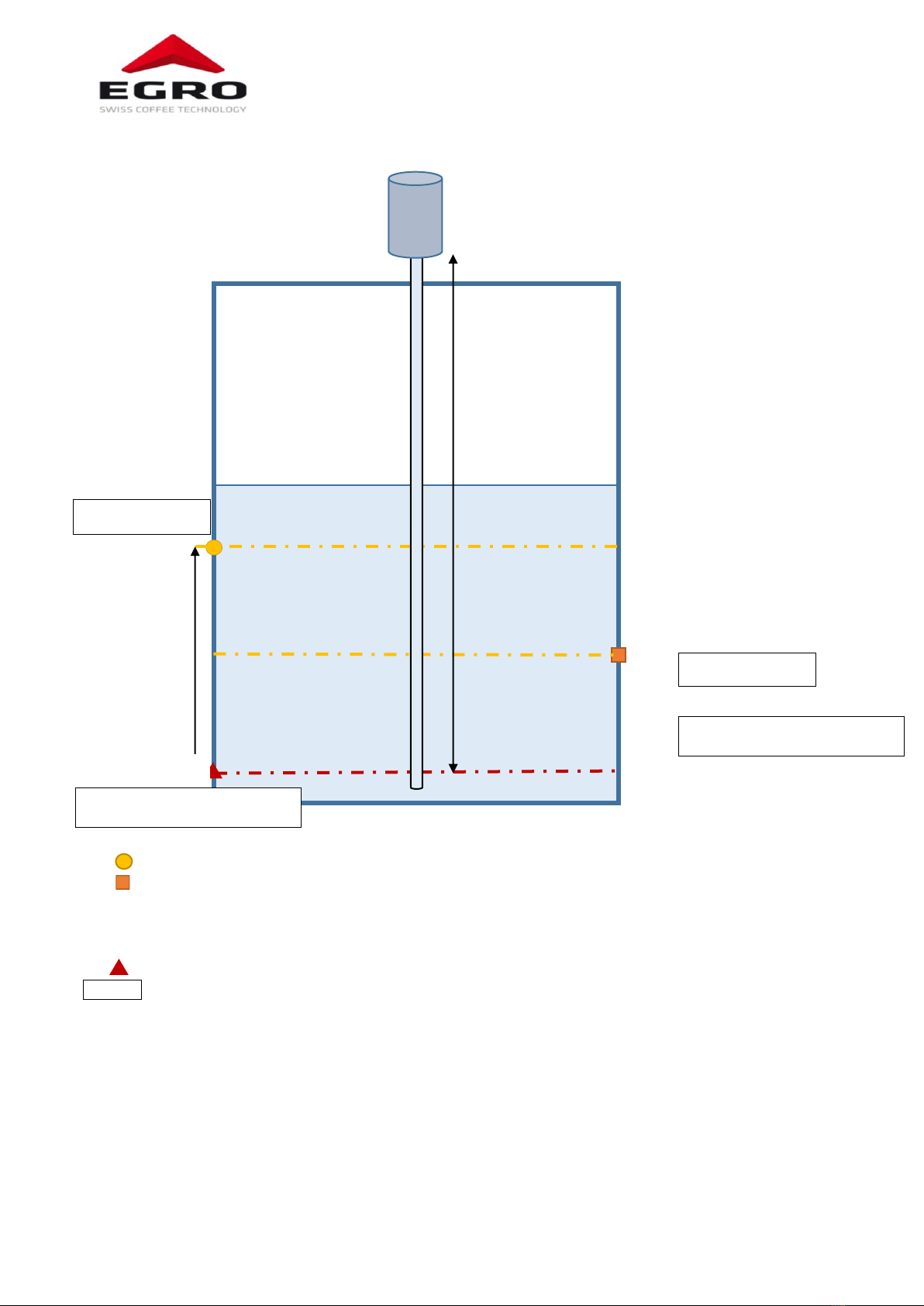
Milk level Alarm concept
Level= X cm (Warning level parameter)
At least one milk product is not possible.
Milk qty. Product > Milk qty. in container
Products with a higher milk quantity than in the container are disabled.
Zero Level
Message
►Action
Zero level
parameter [cm]
X cm
Warning level
parameter [cm]
Low milk level
Residual Milk parameter:
ON
OFF ►All Milk products blocked
Zero Level
Low milk level
Milk missing, refill container
Milk missing, refill container

Egro NEXT
Technical Manual 14 Rev: AA / 09/2018
4.6.7. Configurations Milk system
The configurations shown below are available for the fridge KS9 or as standalone milk pump unit (SMPU).
1L –1M
2L –1M
1 milk –1 machine
2 milk –1 machine
1L –2M
2L –2M
1 milk –2 machines
2 milk –2 machines
Milk pump unit:
1 Milk pumps
2 Milk valves

Egro NEXT
Technical Manual 15 Rev: AA / 09/2018
4.6.8. Cold Milk Foam CMF
Cold Milk Foam (CMF) is an option of the milk system, which should be ordered with the machine/fridge.
CMF is only available for Egro NEXT TopMilk with one milk and one machine! All other versions cannot be
equipped with it.
Special maintenance work is not necessary for the CMF-module. For the rinsing and cleaning of the milk
system the way through the CMF-module will be considered automatically, when a CMF-product was
delivered before.
Cold milk foam can have different stiffness. We integrated three levels with the following parameters:
Liquid
Creamy
Stiff
Milk pump
46%
44%
42%
Air pump
50%
50%
50%
Mixer
100%
100%
100%
The stiffness will be done mainly with the milk pump. Mixer and air-pump should not be adjusted. The
values listed above are considered as guiding value and have to be adjusted, if necessary
Egro NEXT
Technical Manual 16 Rev: AA / 09/2018
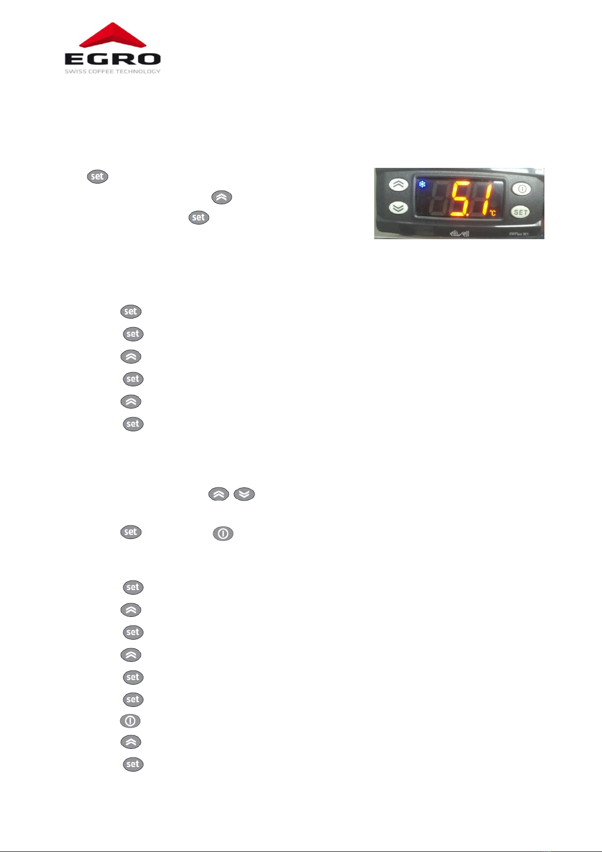
4.7. Fridge NEXT
The temperature controller is on the left side inside the housing of the fridge. After removing the left side
panel, adjustment, unit change and calibration of the temperature can be done.
4.7.1. Temperature adjustment
Press twice.
Modify the temperature with the buttons.
Confirm the new value with .
The temperature must be set to the highest temperature in the
fridge. We recommend to set it to 5 °C/41°F
4.7.2. Temperature offset
Press until <PA1> appears on the display, approx. 5 sec.
Press and <0> will appears on the display
Press until <15> appears on the display
Press once; <dF1> appears on the display
Press until <CA1> appears on the display
Press once; the shown temperature is the offset-temperature, which mean the correction
between the measured and the displayed temperature.
Measure the milk temperature in the fridge. The milk should be cold and for at least three hours
there was no refill.
Adjust temperature with until the value in the display corresponds with the measured
value
Press once and then to leave programming
4.7.3. Change temperature unit
Press until <PA1> appears on the display, approx. 5 sec.
Press once; <PA2> appears on the display
Press and <0> will appear on the display
Press until display shows <15>
Press once; <CP>appears on the display
Press once and on the display appears <dF1>
Press once; <CP>appears again on the display
Press until display shows <di 5>
Press once and on the display appears <LOC>

Egro NEXT
Technical Manual 17 Rev: AA / 09/2018
Press until display shows <dro>
Press once and select the temperature unit with the button:
o<0> = °C <1> =°F
Press twice, to leave programming
4.7.4. Remove milk pumps
Switch off the fridge!
Remove the two screws (a) on the front of the
plastic cover inside the fridge!
Take out milk pump unit.
4.8. Under counter installation
When installing the refrigerator under the counter, some parameters must be adjusted. Please note
chapter 4.6.4.

Egro NEXT
Technical Manual 18 Rev: AA / 09/2018
4.9. Fridge FUM
4.9.1. Temperature adjustment
The temperature adjustment is on the back side of the fridge.
Turn the thermostat to the left to lower the temperature.
Do not turn to the maximum power, as the milk might freeze.
We recommend to mark the ideal temperature on the scale. The ideal
temperature is in the area, where the controller is palced in the picture.
4.9.2. Remove milk pumps
Switch off the fridge!
Remove the two screws
(a) on the upper end of
the milk pump unit inside
the fridge.
Take out milk pump unit.

Egro NEXT
Technical Manual 19 Rev: AA / 09/2018
4.10. Powder Module
The preparation of a powder product is handled with a number of parameters described with the diagram
below. The parameters are split in the one, which are necessary to adjust for each product and the ones
which are handled as a machine parameter.
Make sure to make the water calibration, in the <Product Setup/Powder/Water test> of the EgroTech
app!
Parameters of the EgroTech app are makred with “ET”. All other parameters are configured in the Egro UI
Preparation
time
Start
Stop
Water
Mixer
running
Powder
Powder 1
Powder 2
1
2
3
4
5
6
7
1
Product configuration/ Powder delay
5
Product configuration/ Left powder amount
or Right powder amount
2
Product configuration/ Water delivery
6
“ET” Product set up/ Stop Mixer
3
“ET” Product set up/ Mixer delay
7
Fix values (not configurable)
4
“ET” Product set up/Hopper delay
4.10.1. Powder hopper
The powder hoppers should be cleaned completely once a week.
When reassembling, it is important to have the right order and placements of the parts to secure a proper
function. Some parts are similar and can easily be mixed up.
Front components
Back components
Take care on the knobs!
They are available on the front and on the back of
the powder hopper

Egro NEXT
Technical Manual 20 Rev: AA / 09/2018
4.11. Diagrams, Fuses and Print Boards
The diagram set with the electric and hydraulic diagrams and their legend are delivered with the coffee
machine.
For the detailed description of the print boards with the values of the fuses and the description of the LEDs
we offer a separate document in our download area.
This manual suits for next models
1
Table of contents
Other Egro Coffee Maker manuals


