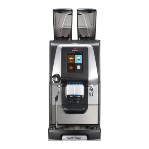
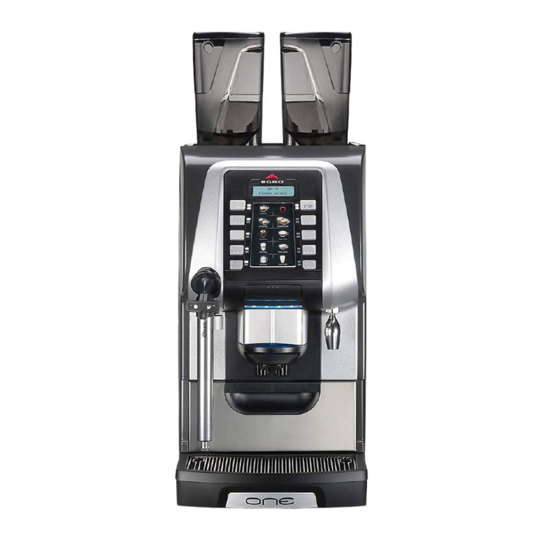
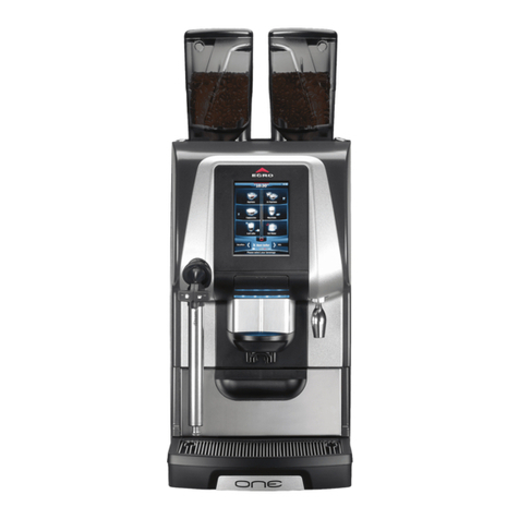
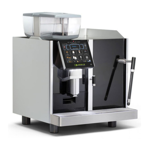
Egro ONE User manual

Technical Manual
ENGLISH

Technical Manual V6.00 2 01.05.2017
Content
1. Introduction.....................................................................................................................................................6
2. Technical data..................................................................................................................................................6
2.1. Dimensions ..............................................................................................................................................6
2.2. Drilling plan..............................................................................................................................................6
2.3. Type label.................................................................................................................................................7
2.4. Outlet.......................................................................................................................................................7
3. Installation.......................................................................................................................................................8
3.1. Electrical connections..............................................................................................................................8
3.1.1. Change power settings ....................................................................................................................8
3.2. Stop using the machine ...........................................................................................................................8
4. Service .............................................................................................................................................................9
4.1. Service Booklet ........................................................................................................................................9
4.1.1. Open machine..................................................................................................................................9
4.2. Preventive Maintenance .........................................................................................................................9
4.2.1. Service interval.................................................................................................................................9
4.2.2. Maintenance....................................................................................................................................9
4.2.3. Lubricants ........................................................................................................................................9
4.2.4. Service kits .....................................................................................................................................10
4.3. Grinder...................................................................................................................................................10
4.3.1. Limit Grinder adjustment...............................................................................................................10
4.3.2. Block Grinder adjustment ..............................................................................................................10
4.3.3. Change Grinder burrs.....................................................................................................................11
4.3.4. SAG –Self adjusting Grinder..........................................................................................................11
4.4. Brewing unit ..........................................................................................................................................12
4.4.1. Remove the brewing unit...............................................................................................................12
4.4.2. Remove the spindle motor.............................................................................................................12
4.4.3. Brewing units.................................................................................................................................12
4.4.4. Calibrating the brewing unit..........................................................................................................12
4.5. Outlet.....................................................................................................................................................13
4.5.1. Adjust outlet ..................................................................................................................................13
4.5.2. Automatic outlet AS.......................................................................................................................13
4.6. New milk system....................................................................................................................................14
4.6.1. Default values................................................................................................................................14
4.6.2. Milk temperature...........................................................................................................................14
4.6.3. Foam structure ..............................................................................................................................14
4.6.4. Correction time ..............................................................................................................................14
4.6.5. Change to pressure sensor.............................................................................................................14
4.6.6. Milk level calibration .....................................................................................................................15
4.6.7. Configurations Milk system ...........................................................................................................17
4.6.8. Cold Milk Foam CMF......................................................................................................................18
4.7. Old milk system .....................................................................................................................................19
4.7.1. Adjusting milk temperature...........................................................................................................19
4.7.2. Adjusting foam quality ..................................................................................................................19
4.7.3. Configuration.................................................................................................................................19
4.8. Under counter installation ....................................................................................................................20
4.9. Fridge KS 9 .............................................................................................................................................20
4.9.1. Temperature adjustment...............................................................................................................20
4.9.2. Remove milk pumps.......................................................................................................................20

Technical Manual V6.00 3 01.05.2017
4.10. Fridge KS7 ..........................................................................................................................................21
4.10.1. Temperature adjustment...............................................................................................................21
4.10.2. Remove milk pumps.......................................................................................................................21
4.11. Powder Module .................................................................................................................................22
4.11.1. Powder hopper ..............................................................................................................................22
4.12. Fuses and Print Boards ......................................................................................................................23
5. Software ........................................................................................................................................................24
5.1. Use of USB .............................................................................................................................................24
5.2. Software update....................................................................................................................................24
5.2.1. Touch .............................................................................................................................................24
5.2.2. Keypad ...........................................................................................................................................24
5.2.3. Recovery ........................................................................................................................................25
5.2.4. Exchange of Touchscreen..............................................................................................................25
5.3. Egro ONE Touch.....................................................................................................................................25
5.3.1. Pictures..........................................................................................................................................25
5.3.2. Product icons .................................................................................................................................25
5.3.3. Upload the icons............................................................................................................................26
5.3.4. Product name customization.........................................................................................................27
5.3.5. Copy customized machine.............................................................................................................28
5.3.6. Video..............................................................................................................................................28
5.3.7. Delete Pictures & Video.................................................................................................................29
5.4. Touchpad...............................................................................................................................................30
5.4.1. Clean the touchpad .......................................................................................................................30
5.4.2. Lifetime..........................................................................................................................................30
5.5. Egro ONE Keypad...................................................................................................................................30
5.5.1. Change Language...........................................................................................................................30
5.6. Backup ...................................................................................................................................................30
5.7. Menu .....................................................................................................................................................31
Settings (Touch).................................................................................................................................................31
Settings (Keypad)...............................................................................................................................................32
Product configuration....................................................................................................................................33
Product setup ................................................................................................................................................34
Machine setup...............................................................................................................................................36
Touch screen..................................................................................................................................................38
Date + Time....................................................................................................................................................39
Cleanings settings..........................................................................................................................................39
Counters ........................................................................................................................................................40
Diagnostic ......................................................................................................................................................42
6. Fault finding...................................................................................................................................................44
6.1. List of errors...........................................................................................................................................44
6.2. List of warnings......................................................................................................................................45
7. Egro BYO ........................................................................................................................................................48
7.1. Tablet communication:..........................................................................................................................48
7.2. Install new App on the tablet ................................................................................................................49
7.3. Generate Backup and send to a smartphone........................................................................................50
7.4. Send Backup-file from a smartphone to a tablet ..................................................................................51

Technical Manual V6.00 4 01.05.2017
8. Egro ONE Multi Drink.....................................................................................................................................53
8.1. Prepare machine ...................................................................................................................................53
8.2. Concept Multi Drink ..............................................................................................................................54
8.3. Software ................................................................................................................................................55
Product configuration....................................................................................................................................55
Touch screen..................................................................................................................................................58
8.4. Egro ONE Touch -> Egro ONE Multi Drink .............................................................................................59
8.5. Egro ONE Multi Drink -> Egro ONE Touch .............................................................................................59
8.6. How to replace SD card .........................................................................................................................60

Technical Manual V6.00 5 01.05.2017
Document history
Date
Author
Version
Changes
28.04.2010
Veith
Version 1.00
First official release
30.07.2010
Veith
V 1.01
French updated –Chap 4. Service updated and new sub chapters added
–Menu updated –Legend added –Electric diagram updated
Veith
V2.00 draft
French updated –diagrams updated –Error and warnings updated –
Menu extended to SW version 2.00 –Pictures added
04.07.2012
Veith
V 3.00
Powder module added –New software 3.00 –new diagrams –Chap. 4
and 5 extended
15.04.2014
Veith
V 3.01
New milk system, chapt. 2.4, 4.5 added –new diagrams & legend –
Software tree updated to V4.00
Old milk system moved to chapter 4.6
Chapter 4.4 - 4.7 changed to 4.7 –4.9
15.09.2014
Veith
V 4.00
Ch. 4 updated and extended –KS9 added –Software updated –
chapters with reference to user manual removed –parameters
corrected
07.03.2016
Veith
V 5.00
Milk level with pressure sensor added –Typelabel exchanged –Chapter
Touch extended –SW V7.00
Egro ONE Multi Drink added
01.05.2017
Veith
V 6.00
SAG, CMF, AS and BYO added
SW V 8.10
Single language manual –German –French –English
Service chapter reorganized
Take out Menutree, Diagrams and Platines

Technical Manual V6.00 6 01.05.2017
1. Introduction
This manual is intended to give you additional information to the machines Egro ONE, Egro TWO and Egro BYO which are
not in the installation manual delivered with the machine or in the user manual. This manual will be updated on a
regularly base. The updates are available in our Download area without further notification.
In this manual only information, which are not given in the above mentioned manuals.
Please check yourself on www.ranciliogroup.com/Support
The user manuals of the machines are available for download on our homepage www.ranciliogroup.com
2. Technical data
2.1. Dimensions
The dimensions are given in the manuals of the machines. Detailed drawings will be distributed via the homepage.
2.2. Drilling plan
1
Machine layout
2
Hole for pipes and cables
3
Grounds drawer
4
Machine foot

Technical Manual V6.00 7 01.05.2017
2.3. Type label
The type label is in the machine. Take out the ground drawer and it is on the left sidewall.
1
9
2
10
3
11
4
12
5
6
7
8
1
Manufacturer
5
Conformity marks
9
EC Conformity mark
2
Model and version
6
Total absorption
10
Serial number
3
Voltage
7
Motor power
11
Pin
4
Frequency
8
Date of manufacture
12
Max. boiler/static pressure
2.4. Outlet
1
Coffee
2
Hot Water
3
Milk/Milk foam
4
Powder product
5
Cold Milk Foam (CMF)
1
4
4
3
3
2
1
3
2
5
5
5

Technical Manual V6.00 8 01.05.2017
3. Installation
The installation of the coffee machine is described in the installation manual.
3.1. Electrical connections
The machines are delivered according to the information on the type label, but they offer different electrical connections.
Power supply
Power rating
Identification
“Reduced Power”
220-240V 3~, 50/60Hz
6.0kw
2P
OFF
380-415V 2N~, 50/60Hz
6.0kw
2P
OFF
220-240V 1N~ 50/60Hz
6.0kW
1P
OFF
220-240V 1N~ 50/60Hz
3.6kW
LP
ON
208/240 V2ph~, 60Hz
5/6kW
-
OFF
3.1.1. Change power settings
The power settings can be changed depending on the available power supply. The electrical diagram in the appendix
shows the different ways to connect the machine.
When connecting the machine to 220-240V 1N~ 50/60Hz with 16A fuse the parameter “Reduced Power” has to be
changed to “ON”.
3.2. Stop using the machine
Warning! Only a qualified person is allowed to disconnect the machine from the main power supply!
-Clean the machine, on machines with milk a milk cleaning has to be done!
-Switch off the circuit breaker
-Disconnet from water and electric power, if necessary.
-Cover the machine and place it in a dry room, not exposed to environmental elements
Final Stop: Cut of the power supply cable. Consign the machine to authorized companies for its disposal.

Technical Manual V6.00 9 01.05.2017
4. Service
4.1. Service Booklet
The service booklet is in each machine for information of maintenance done. It has space for breakdowns, which should
be noted down by the service technician.
4.1.1. Open machine
Open machine front: Open front cover, remove ground drawer and loosen screw
Remove side panels: Loose screws in the top cover plate. Then pull side panels upwards and remove.
4.2. Preventive Maintenance
Preventive maintenance ensures a continuous quality of products and reduces unscheduled breakdowns. During
preventive maintenance service will be done and necessary spare parts will be exchanged.
The bases for preventing maintenance are kits with all necessary parts. They are available as “Service kit” and
“Extension kit”.
The preventive maintenance is driven by the number of brewing cycles and/or the predefined time. Reaching the
number of cycles or the time, the coffee machine indicates the message "Perform the preventive maintenance".
We recommend adjusting the maximum brewing cycles to 40’000 cycles and the time to 1 year.
The brewing cycles depend on various criteria as regularity of brewing and cleanings, composition of water, cleaning
product, climatic conditions, etc.
In case of unfavorable conditions adjust the number of brewing cycles.
4.2.1. Service interval
Cycles
40'000
80'000
120'000
160'000
200'000
Time
1 Year
2 Years
3 Years
4 Years
5 Years
Service kit
Service kit &
Service kit iSteam
Service kit &
Extension kit
Service kit &
Service kit iSteam
Service kit
4.2.2. Maintenance
Tables with maintenance tasks for each type of machine are available in our download area. They list the tasks and the
parts and are given with the necessary drawings.
4.2.3. Lubricants
The lubricant table informs which lubricant has to be used according the application. The use of not specified lubricants
can shorten the lifetime extremely.
No
Description
Type
ID
Thermal Range
Area of Application
1
High performance lubricant
Berulub
FG-H 2 SL
059246
-45 - +160°C
All connections:
Boiler fittings, tea- and steam wand,
piston motors
Used for connections and mechanical
moving parts
2
High performance lubricant
Berulub
SIHAF 2
059247
-45 -+160°C
For all rubber seals like:
NBR, EPDM, Viton
Not applicable for Silicon O-Ring!
3
Synth. Assembly Grease
Klübersynth
UH1
64-2403
054567
-30 - +140°C
Piston O-Rings
Do not use with EPDM rubbers!

Technical Manual V6.00 10 01.05.2017
4.2.4. Service kits
The service kits are listed below with their ID-number. As the content can change based on technical improvements, we
do not list the content. The part, being part of the sets can be seen in our WEB-shop.
Description
ID-Number
Valves
Service kit ONE Pure Coffee Sirai
10701238
Sirai
Service kit ONE Pure Coffee NMS
10701087
Service kit ONE Milk
10701102
Service kit ONE Milk NMS ACL
10701086
ACL
Service kit ONE Milk NMS Sirai
10701237
Sirai
Service kit special Milk ACL
10701322
ACL
Service kit special Milk Sirai
10701323
Sirai
Service kit iSteam ONE
00061105
Extension-kit ONE NMS
10701088
4.3. Grinder
4.3.1. Limit Grinder adjustment
The grinder adjustment from outside can be limited with the springs we deliver with the machine.
Make first the basic adjustment and then mount the spring as shown in the pictures to limit the grinder adjustment.
4.3.2. Block Grinder adjustment
To block the grinder adjustment, make first the grinder adjustment and then
turn on the blocking screw on the left and on the right inside the machine for
blocking the adjustment wheel.

Technical Manual V6.00 11 01.05.2017
4.3.3. Change Grinder burrs
A counter for the coffee is integrated in the software, which we recommend to set to 1000 kg. As soon as the amount is
reached, a message will inform to replace the burrs. The burrs should be replaced as well, when the grinding time
becomes noticeably longer or the grind becomes irregular.
-Close the bean hopper and grind the beans still in the grinder
-Switch off the machine
-Remove the bean hopper and the top plate
-Empty the grinder completely with a vacuum cleaner
-Remove the grinder adjustment from the grinder
-Turn the upper burr-holder counter-clockwise until the head emerges completely;
-Unscrew the screws and remove the burrs from the burr-holder:
-Carefully clean the burr supports, the burr-holder thread and its housing;
-Position the new burrs in their holders and block them firmly in place;
-Reassemble the machine, performing the previous steps in reverse.
-Switch on the machine
-Calibrate the new burrs.
4.3.4. SAG –Self adjusting Grinder
The grind setting will be managed according the brewing time of the coffee and not by the manual adjustment. This is
done with two motors with worm gear, which are mounted at the grinders.
To work with SAG, the extension board is a precondition as the calculation and the adjustment of the motors is managed
by the board. SAG is available as option for all machines of the Egro ONE Series.
When installing the machine, the grinder setting must be done as written in the installation manual. The parameter
<Product Setup> <Grinder> <SAG> <Module Type> has to be set to “Manual”.
When the grinder setting is finished you can activate SAG
SAG is working with a reference product for each grinder. Most time it is Espresso for the left grinder and coffee for the
right one. The parameters which have to be considered for the reference product are: grams, pulses, pre-infusion and
pressure. If for the left grinder product, no 3 “espresso” is selected, not only this product will be taken in account, but all
products, which have the same values for the above mentioned parameters, e.g. “Cappuccino”.
Take care at a BYO-machine that the reference products on the machine and on the tablet are the same.
The change of grinder burrs will be done the same way as described in the chapter above.

Technical Manual V6.00 12 01.05.2017
4.4. Brewing unit
4.4.1. Remove the brewing unit
Unlock the frame, remove left sheet metal, and disconnect the tubes from the pistons and the cables from the main
board. Unscrew fastening screws and disassemble brewing unit.
4.4.2. Remove the spindle motor
To remove the spindle motors, the screws at the top or at the bottom must be removed. Subsequently, the motor with
the piston are pulled out up or down and can be taken apart.
4.4.3. Brewing units
The Egro ONE has two generations of brewing units, which can be seen below. The main differences of the new one
(BC18) are the plastic parts for the funnel, the ejector and the ground slider. The brewing unit is fixed with screws on top
and bottom (BC18) and not with bolts (L61). The brewing chamber is fixed with openings and screws in the metal part.
L 61
BC18
4.4.4. Calibrating the brewing unit
When replacing the brewing unit (BC18) as well as the exchange of spindle motors, the brewing unit must be recalibrated.
The auto calibration can be found in <Machine setup> under the <Factory settings>.

Technical Manual V6.00 13 01.05.2017
4.5. Outlet
All machines have an outlet, which is manually adjustable in the height. This outlet has a handle to move the
outlet.
4.5.1. Adjust outlet
The outlet can be adjusted from the force you need to move.
4.5.2. Automatic outlet AS
The Automatic Spout (AS) is driven by a motor and offer the possibility to define five different cup heights,
which will be assigned to the products. This is also valid for hot water products, when the machine has a
central outlet.
If the machine has the hot water outlet on the side, the cup height must be defined as “top” so that no
movement takes place.
Machines with AS have no handle on the outlet. Anyhow it is possible, when needed, to move the outlet
slowly by hand.
This should only be done, if the outlet does not move anymore with the motor.

Technical Manual V6.00 14 01.05.2017
4.6. New milk system
4.6.1. Default values
The default values are considered as recommendations. As not all systems work the same, they might be adjusted. The
values are set for a milk temperature of 5°C.
The temperature setting “Medium” is to be used for foam products.
The higher the value of the milk temperature (low/medium/high) the more milk will be delivered. As the steam delivery is
constant the milk product will be cooler.
The higher the value of the foam structure (fine/medium/big) the more air will be pumped. By adding air, the
temperature of the milk products will increase.
Top Milk
Milk temperature
High speed (Low milk temp.)
95
Medium speed (Medium milk temp.)
70
Low speed (High milk temp.)
57
Correction time
1s
Top Milk & Quick Milk
Foam structure
Fine
33
Medium
38
Big
42
4.6.2. Milk temperature
First, the milk temperature has to be adjusted. This is done in percentage of the power of the milk pump on the Top Milk
XP machines and with restrictors for the Quick Milk.
Please take care, that foam products always have a higher temperature than milk products with the same settings.
4.6.3. Foam structure
We recommend using only one temperature setting for foam products. This simplifies the setting of the foam structure
(in %). When changing the temperature setting the foam structure has to be adjusted.
4.6.4. Correction time
The correction time should be adjusted in a way that the milk reaches the frother head when the steam will be switched
on. This can be seen by a seriously increase of steam or by the switching of the steam valves.
If the correction time is too short, it could happen that after a rinsing no milk will be charged.
4.6.5. Change to pressure sensor
All configurations of the new milk system can work with a level measurement based on a pressure sensor. Order the
pressure sensor according to the single or double milk configuration of your system and follow the instruction given here
for each sensor.
For the sensor(s), an auto calibration is available and the technician can adjust it for the milk container in use at the customer.
-Remove the milk pump unit from the fridge
-Remove the tube from the white plastic part and take out the milk tube
-Remove the circlip and move the plastic part through the opening
-Insert the new plastic part with the mounted pressure sensor. The sensor with the red point on it is the standard
/left sensor, the blue point shows the right one, which is only used with two kind of milk.
Attention: Take care not to damage the cables and the sensor
-Secure the plastic part with the circlip and install the pump unit in the right place
-Plug in the milk tubes
-Connect the wires of each sensor together with the other sensor.
-Connect them to the mainboard of the coffee machine (connector J3)
-Make the auto calibration for each sensor.

Technical Manual V6.00 15 01.05.2017
The cable for the pressure sensor is done with two numbers:
10110976 Wiring pressure sensor NMS ONE (to connect with the machine)
10110835 Wiring pressure sensor NMS 1Milk (to connect with 1 pressure sensor)
10110839 Wiring pressure sensor NMS 2Milk (to connect with 2 pressure sensor)
When ordering the machine with KS9, the cable is in the fridge and has to be connected to J34 on the control board or to
J4 on the extension board, if it is in the machine.
When ordering the machine for FUM or SMPU the cable in the coffee machine is already mounted.
4.6.6. Milk level calibration
ATTENTION! Set <Product Setup/Milk/Module Type> first to “Fridge”.
The menu for the level measurement is in the software under Product Setup/Milk.
The machine has an automatic calibration, which allows the technician to adjust the milk container the customer is using.
The calibration should be done, when the machine is correctly positioned on a stable, leveled surface.
The auto calibration for the milk level guides with a sequence of steps through the procedure. It takes some minutes
depending on the capacity of the milk container. When the “Fill”-button appears, press it at least up to the point that the
metallic restrictor holder is completely in the water.
Attention, water is coming out of the outlet of the coffee machine!
As preparation take care that the milk tube is hanging free in the container and almost touch the bottom of it.
When having two machines, which take the milk out of the same container(s), take care to set the Zero level a little bit
higher to avoid that the products cannot be finished as both machine can take out milk at the same time.
Perform the auto calibration for both machines independently (not together).

Technical Manual V6.00 16 01.05.2017
Milk level Alarm concept
Level= X cm (Warning level parameter)
At least one milk product is not possible. Milk qty. Product < Milk qty. in container
Products with less milk quantity than in the container are disabled.
Zero Level
Message
►Action
Zero level
parameter [cm]
X cm
Warning level
parameter [cm]
Low milk level
Residual Milk parameter:
ON
OFF ►All Milk products blocked
Zero Level
Low milk level
Milk missing, refill container
Milk missing, refill container

Technical Manual V6.00 17 01.05.2017
4.6.7. Configurations Milk system
The configurations shown are available for the fridges KS9, KS7 or as independent milk pump unit (SMPU).
1L –1M
2L –1M
1 milk –1 machine
2 milk –1 machine
1L –2M
2L –2M
1 milk –2 machines
2 milk –2 machines
Milk pump unit:
1 Milk pumps
2 Milk valves

Technical Manual V6.00 18 01.05.2017
4.6.8. Cold Milk Foam CMF
The milk system received additional components, to produce Cold Milk Foam (CMF).
This should be ordered with the machine, as a later retrofit is possible but very complex.
CMF is only available for Top Milk with one milk and one machine! All other versions cannot be equipped with
it.
At the rinsing and cleaning of the machine the way through the CMF-module will be considered, when a CMF-
product was produced before. Additional maintenance work is not necessary for the CMF-module.
Cold milk foam can have different stiffness. We integrated three levels with the following parameters:
Liquid
Creamy
Stiff
Milk pump
46%
44%
42%
Air pump
50%
50%
50%
Mixer
100%
100%
100%
The stiffness will be done mainly with the milk pump. Mixer and air-pump should not be adjusted.
If the retrofit with the CMF-module is planned, take care that the coffee machine must have the extension
board.

Technical Manual V6.00 19 01.05.2017
4.7. Old milk system
4.7.1. Adjusting milk temperature
The milk temperature will be adjusted by the flow. If the requested temperature is not reached, restrictors can be used.
Restrictors for cool box are available in Ø 1.1 –2 mm. Check steam pressure, if necessary.
4.7.2. Adjusting foam quality
The foam quality is adjusted by the quantity of air and done with restrictors. Attention! The foam quality can influence
the milk temperature! Restrictors for air are available from Ø 0.3 –1.1mm
a. Quick Milk/Top Milk
At the Egro ONE Quick Milk and Top Milk the restriction for the adjustment of the foam quality is placed at the white air
block on the left opening. The opening on the side is closed.
b. Top Milk XP
At the Egro ONE Top Milk XP the restriction for the adjustment of the foam quality is placed at the white air block on the
right side.
4.7.3. Configuration
The configuration shown is only available for the fridges KS7.
Milk pump unit:
1 –2 Milk pumps
3 Milk level sensor
4 –5 Switch valves
6 Air pump

Technical Manual V6.00 20 01.05.2017
4.8. Under counter installation
When the refrigerator is placed under the counter a restrictor (0.4mm) has to be added to the air pipe between the fridge
and the coffee machine. The restriction can be placed anywhere on the air pipe; however, we suggest to put it in the
junction between the coffee machine and the fridge, which is easy to reach.
With this modification, the fridge works successful even with milk pipes of more than 1.5m.
Without this restriction, the milk pipes might not be emptied completely by the system after the automatic water rinsing and
so the first milk product after the rinsing would show some water coming out of the spout before the milk arrives.
The settings have to be modified in < Product setup> <Milk>:
NMS
Old milk system
Correction time
2 s
1 s
Rinsing time
0.5 s
0.5 s
Blowout time
1.5 s
1.5 s
4.9. Fridge KS 9
4.9.1. Temperature adjustment
The temperature adjustment is on the left side inside the housing. After
removing the left side panel, it can be adjusted.
Press the SET button twice. Modify the temperature and confirm with the SET
button. The temperature is set to the highest temperature in the fridge.
4.9.2. Remove milk pumps
Switch off the fridge!
Remove the two screws (a) on the front of the plastic cover
inside the fridge. Take out milk pump unit.
Other manuals for ONE
10
Table of contents
Other Egro Coffee Maker manuals


