Elko iNELS RFSTI-111B User manual

02-216/2016 Rev.0
RFSTI-111B
Overheating protection of room
EN
Made in Czech Republic
Characteristics /
• The component measures temperature in the range of 15...35 °C external sensor and on the basis
of the set temperature switches air conditioning.
• It is particularly suitable for rooms with a tropical climate.
• With the window / door sensor programmed, when the window / door is opened, the device
relay contact is automatically disconnected, thereby saving unnecessary energy consumed for
cooling when the window / door is open.
• The BOX design lets you mount it right in an installation box, a ceiling or controlled appliance
cover.
• It enables connection of the switched load up to 12 A (3000 VA).
• Up to 4 RFDW-100 detectors can be connected to one RFSTI-111B device.
• Range up to 160 m (in open space), if the signal is insufficient between the controller and unit,
use the signal repeater RFRP-20 or protocol component RFIO2that support this feature.
• For components it is possible to set the repeater function via the RFAF/USB service device.
• Communication frequency with protocol iNELS RF Control2(RFIO2).
• External sensor TC (0 ..+70 °C) or TZ (-40 ..+125 °C) for length of 3 m, 6 m, 12 m.
mounting in an installation box
Assembly /
ceiling mounted
Avoid rapid temperature changes, direct sunlight and excessive moisture.
The temperature units should not be located near windows or heating
equipment, etc., which could affect the internal temperature sensor.
°C
Connection /
1 / 3
RFSTI-111B/24V
T T
L
N
12-24 V AC/DC
T T
L
N
RFSTI-111B/230V
RFSTI-111B/120V
Radio frequency signal penetration through various construction materials /
60 - 90 % 80 - 95 % 20 - 60 % 0 - 10 % 80- 90 %
brick walls wooden structures
with plaster boards
reinforced
concrete metal partitions common glass
☺
☺
☺
☺
☺
RFRP-20
For more information, see“Installation manual iNELS RF Control”:
http://www.elkoep.com/catalogs-and-brochures
Unidad de temperatura de protección
ES
ELKO EP, s.r.o. | Palackého 493 | 769 01 Holešov, Všetuly | Czech Republic | e-mail: [email protected] | Support: +420 778 427 366
ELKO EP ESPAÑA, S.L. | C/ Josep Martinez 15a, bj | 07007 Palma de Mallorca | e-mail: [email protected] | Tel.: +34 971 751 425 | Fax: +34 971 428 076
www.elkoep.com / www.elkoep.es
No exponga la unidad a los cambios bruscos de temperatura, luz solar di-
recta y la humedad excesiva. Las unidades de regulación de temperatura
coloque de manera que no esten cerca de ventanas o equipos de calefac-
ción, etc., lo que podría afectar el sensor de temperatura.
montaje en caja universal
Montaje
montaje al falso techo
Conexión
• El dispositivo mide la temperatura en rango de 15 .. 35 °C mediante un sensor externo y a base
de la temperatura ajustada enciende un aire acondicionado.
• Es especialmente adecuado para habitaciones de hotel.
• Al emparejar el sensor de ventana / puerta, cuando se abre la ventana / puerta, el contacto del
relé del dispositivo se desconecta automáticamente, ahorrando energía de aire acondicionado
innecesaria cuando la ventana / puerta está abierta.
• Versión „pastilla“ ofrece montaje directamente a la caja de instalación, techo o a la cubierta
del aparato.
• Se puede conectar un máximo de 4 detectores RFDW-100 a un RFSTI-111B.
• Alcance de hasta 160 mts (al aire libre), en caso de señal insuficiente entre controlador y la unidad se
puede utilizar el repetidor RFRP-20 o unidades con protocolo RFIO2, las cuales tienen esta función.
• En las unidades es posible ajustar la función del repetidor a través de un dispositivo de insta-
lación RFAF/USB.
• Frecuencia de comunicación con protocolo iNELS RF Control2(RFIO2).
• Sensor externo TC (0 ..+70 °C) o TZ (-40 ..+125 °C) en longitud de 3 m, 6 m, 12 m.
Característica
Transmisión de señales de radiofrecuencia en varios materiales de la construcción
pared de ladrillo estructuras de
madera con placas
de yeso
hormigón armado chapas
metálicas vidrio normal
Para obtener más información, consulte “Installation manual iNELS RF Control”:
http://www.elkoep.com/catalogs-and-brochures
02-216/2016 Rev.0
RFSTI-111B
Overheating protection of room
EN
Made in Czech Republic
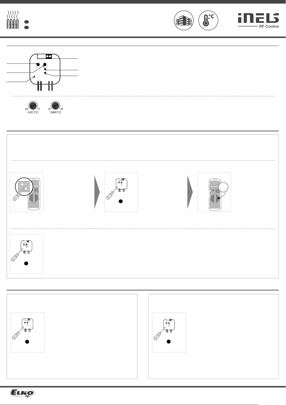
Indication, manual control /
LED REG
terminal board /
hysteresis /
temperature /
LED STATUS
• HYST - setting hysteresis in range 0.5-5°C.
• TEMP - setting temperature in range 15-35°C.
• Terminal board - connection for an external temperature sensor.
• Green LED REG - indication regulation.
• LED STATUS - relay switching indication.
• Programming is performed by pressing the PROG button for more
than 1s.
In programming and delete mode, each time the detector is pro-
grammed, the LED on the device lights up for a single long flash - this
indicates the incoming command.
button /
2 / 3
ON
1 2
Delete one detector from memory /
Delete actuator /
Deleting the entire memory /
PROG > 5s
1 x PROG > 8s
1 x
Pull the battery out of the detector. By pressing the programming
button on the actuator for 5 seconds, deletion of one detector
activates. The LED flashes in an interval of 1s.
Inserting the battery into the detector will send a signal to
delete the device memory.
The LED goes out and the actuator returns to operating mode.
Functions and programming /
While holding the tamper,
insert the battery into the de-
tector (see detector manual).
Tamper Hold Min. 1s after in-
serting the battery. The detec-
tor is then stored in the RFSTI-
111B memory.
Press of programming but-
ton on receiver RFSTI-111B
shorter then 1 second will fin-
ish programming mode, LED
switches off.
Press of programming but-
ton on receiver RFSTI-111B for
1second will activate receiver
RFSTI-111B into programming
mode. LED is flashing in 1s
interval.
Programming /
The external sensor senses the temperature of the room, turns the air conditioner on and
off according to the set temperature. Responds to commands from the detector - when you
open the window, turn off air conditioning.
2
PROG > 1s
1 x
4
PROG >1s
1 x
Description of function /
3RFWD-100
ON
1 2
+
CR2032
ON
1 2
1Set the DIP-1 to the OFF posi-
tion on the detector and set
the DIP-2 to the ON position.
RFWD-100
By pressing the programming button on the actuator for 8 sec-
onds, deletion occurs of the actuator's entire memory. LED
flashs 4x in each 1s interval.
The actuator goes into the programming mode, the LED flashes
in 0.5s intervals (max. 4 min.).
You can return to the operating mode by pressing the Prog but-
ton for less than 1s.
Unidad de temperatura de protección
ES
ELKO EP, s.r.o. | Palackého 493 | 769 01 Holešov, Všetuly | Czech Republic | e-mail: [email protected] | Support: +420 778 427 366
ELKO EP ESPAÑA, S.L. | C/ Josep Martinez 15a, bj | 07007 Palma de Mallorca | e-mail: [email protected] | Tel.: +34 971 751 425 | Fax: +34 971 428 076
www.elkoep.com / www.elkoep.es
Indicación, control manual
terminales
histéresis
temperatura
• Terminales - conexión para sensor externo de temperatura.
• LED REG verde – indicación de regulación.
• LED STATUS – indicación de estado de relé.
• Programación se realiza mediante el botón PROG > 1s.
En el modo de programación y borrado, durante la programa de cada
detector el LED del dispositivo le da un parpadeo largo. - así se indica
la recepción de orden.
• HYST – ajuste de histerésis en rango de 0.5-5°C.
• TEMP – ajuste de temperatura requerida en rango de 15-35°C.
botón PRG
Funciones y programación
Externí čidlo snímá teplotu v místnosti a spíná klimatizaci dle nastavené teploty. Reaguje na
povel detektoru - při otevření okna vypne klimatizaci.
Descripción de la función
Mientras mantiene presionado
el tamper, inserte la batería en
el detector (consulte el manual
del detector). Mantenga tam-
per pulsado min. 1s después de
insertar la batería. Así el detec-
tor se guarda en la memoria del
R FS T I -111B .
Pulsando el botón de
programación de la unidad
RFSTI-111B durante menos
de 1 segundo, terminará el
modo de programación. LED
se apaga.
Pulsando el botón de
programación de la unidad
RFSTI-111B durante más de
1 segundo, entra al modo de la
programación. LED parpadea
en intervalo de 1 segundo.
Programación
Eliminación de un detector desde la memoria
Borrar la unidad
Borrar toda memoria
Retire la batería del detector. Con pulsación del botón de pro-
gramación en el RFSTI-111B durante 5 segundos se activa la
eliminación de un detector. LED parpadea en intervalos de 1s.
La inserción de la batería al detector emite una señal y el detec-
tor se elimina desde la memoria.
LED se apaga y la unidad vuelve al modo operativo.
En el detector ajusta el DIP-1 a
la posición OFF, ajusta el DIP-2
a la posición ON.
Con un largo pulso del botón de programación de la unidad
durante 8 segundos se borrará toda memoria de la unidad. LED
4x parpadeará en intervalo de un segundo.
Unidad entra al modo de programación, el LED parpadea en
intervalos de 0.5s (máx. 4 min.).
Para volver al modo operativo, pulse el botón Prog por menos
de 1 segundo.

02-216/2016 Rev.0
RFSTI-111B
Overheating protection of room
EN
Made in Czech Republic
Technical parameters /
* Temperature sensor input is at the supply voltage potential.
Attention:
When you instal iNELS RF Control system, you have to keep minimal distance 1 cm between each units.
Between the individual commands must be an interval of at least 1s.
Instruction manual is designated for mounting and also for user of the device. It is always a part of its packing.
Installation and connection can be carried out only by a person with adequate professional qualification upon
understanding this instruction manual and functions of the device, and while observing all valid regulations.
Trouble-free function of the device also depends on transportation, storing and handling. In case you notice any
sign of damage, deformation, malfunction or missing part, do not install this device and return it to its seller. It
is necessary to treat this product and its parts as electronic waste after its lifetime is terminated. Before starting
installation, make sure that all wires, connected parts or terminals are de-energized. While mounting and servicing
observe safety regulations, norms, directives and professional, and export regulations for working with electrical
devices. Do not touch parts of the device that are energized – life threat. Due to transmissivity of RF signal, observe
correct location of RF components in a building where the installation is taking place. RF Control is designated only
for mounting in interiors. Devices are not designated for installation into exteriors and humid spaces. The must not
be installed into metal switchboards and into plastic switchboards with metal door – transmissivity of RF signal is
then impossible. RF Control is not recommended for pulleys etc. – radiofrequency signal can be shielded by an
obstruction, interfered, battery of the transceiver can get flat etc. and thus disable remote control.
Warning
3 / 3
Supply voltage:
Apparent input:
Dissipated power:
Supply voltage tolerance:
Temperature measurement input:
Temp. measurement range and
accuracy:
Output
Number of contacts:
Rated current:
Switching power:
Peak current:
Switching voltage:
Min. switching power:
Insulation voltage between
relay outputs and internal circuits:
Isolates. voltage open relay
contact:
Mechanical service life:
Electrical service life (AC1):
Control
Transmitter frequency:
Range:
Other data
Operating temperature:
Storage temperature:
Indication of relay switch:
Indication regulation:
Operating position:
Mounting:
Protection:
Overvoltage category:
Contamination degree:
Outlets (CY wire, cross-section, length):
Dimensions:
Weight:
Unidad de temperatura de protección
ES
ELKO EP, s.r.o. | Palackého 493 | 769 01 Holešov, Všetuly | Czech Republic | e-mail: [email protected] | Support: +420 778 427 366
ELKO EP ESPAÑA, S.L. | C/ Josep Martinez 15a, bj | 07007 Palma de Mallorca | e-mail: [email protected] | Tel.: +34 971 751 425 | Fax: +34 971 428 076
www.elkoep.com / www.elkoep.es
230 V AC / 50-60 Hz 120 V AC / 60 Hz 12-24 V DC / AC 50-60 Hz
9 VA / cos φ = 0.1 9 VA / cos φ = 0.1 -
0.7 W
+10 %; -15 %
1x external TZ/TC temperature sensor input / 1x entrada para sensor externo de temperatura TZ/TC*
+15 .. +35 °C; 0.5 °C of the range / del rango
1x switching / NA (AgSnO2)
12 A / AC1
3000 VA / AC1, 288 W / DC
30 A / max. 4s at 10 % / máx. 4 s en ciclo de trabajo 10%
250 V AC1 / 24 V DC
100 mA / 10 V
basic insulation (Cat. III surges by EN 60664-1) /
alapszigetelés (cat. sobretensión III sobre EN 60664-1)
1 kV
3x10⁷
5x10⁴
866 MHz, 868 MHz, 916 MHz
up to / hasta 160 m
-15 ... + 50 °C
-30 ... + 70 °C
red / rojo LED
green / verde LED
any / cualquiera
free at lead-in wires / libre en los cables de conexión
IP30
III.
2
2 x 0.75 mm2, 2 x 2.5 mm2, 90 mm
49 x 49 x 21 mm
50 g
Tensión de alimentación:
Consumo aparente:
Consumo de perdida:
Tolerancia de alimentación:
Entrada para sensor externo:
Rango y precisión de medición:
Salida
Número de salidas:
Corriente nominal:
Potencia conmutable:
Pico de corriente:
Tensión conmutable:
Corriente de conmutación mínima:
Tensión de aislamiento entre las
salidas del relé y circuitos internos:
Tensión de aislamiento del
contacto de relé abierto:
Vida mecánica:
Vida eléctrica (AC1):
Control
Orden RF desde controlador:
Rango al aire libre:
Más información
Temperatura de funcionamiento:
Temperatura de almacenamiento:
Indicación de regulación:
Indicación de estado de relé:
Posición del funcionamiento:
Montaje:
Protección:
Categoría de sobretensión:
Grado de contaminación:
Salidas (hilos CY, sección, longitud):
Dimensiones:
Peso:
* Entrada del sensor de temperatura está en el potencial de la tensión de red.
Advertencia:
En la instalación de iNELS RF Control debe haber una distancia mínima entre las diferentes
unidades de un centímetro.
Entre los diferentes ordenes debe pasar al menos 1s.
El manual de uso está dirigido para la instalación y el usuario del dispositivo. Manual siempre está incluido en
embalaje. La instalación y conexión puede realizar sólo personal con adecuadas cualificaciones profesionales, de
conformidad con todas las regulaciones aplicadas, y que está perfectamente familiarizado con estas instrucciones
y funciones del dispositivo. Función del dispositivo también depende del transporte, almacenamiento y la
manipulación. Si se observa cualquier signo de daño, deformación, mal funcionamiento o pieza que falta, no instale
este producto y devolvelo al vendedor. Con el producto y sus componentes debe ser tratado después de su vida
útil como con residuos electrónicos. Antes de iniciar la instalación, asegúrese de que todos los cables, partes o
terminales conectados están sin la conexión a la red. En el montaje y el mantenimiento se deben observar las
normas de seguridad, normas, directivas y reglamentos para trabajar con equipos eléctricos. No toque las partes
del dispositivo que están conectadas en la red - puede producir peligro de vida. Debido a la transmisibilidad de la
señal RF, observe la correcta ubicación de los componentes RF en un edificio donde la instalación se lleva a cabo. RF
Control está diseñado para montaje en interiores, las unidades no están diseñados para la instalación en exteriores
y espacios húmedos, no se pueden instalar en cuadros eléctricos de metal y en cuadros eléctricos plásticos con
puerta de metal - lo que empeora transmisividad de la señal RF. RF Control no se recomienda para el control de
dispositivos que ofrecen funciones vitales o para controlar dispositivos tales como bombas, el. calentadores sin
termostato, ascensores, montacargas, etc. - Señal de radiofrecuencia puede estar bloqueado por una obstrucción,
interferida, la batería del controlador puede estar ya sin energía, etc. y por lo tanto el control remoto puede ser
incapacitado.
Advertencia
Especificaciones técnicas
This manual suits for next models
1
Other Elko Thermostat manuals


Popular Thermostat manuals by other brands

Vimar
Vimar 2911 user manual

ICM Controls
ICM Controls SC1901L Installation, operation & application guide

Honeywell
Honeywell T5+ user manual

Nexans
Nexans MILLITEMP CDFR-003 User's manual & installation instructions

White Rodgers
White Rodgers 1F80-0224 Installation and operating instructions

Daikin
Daikin EKRTW Operation manual


Honeywell
Honeywell PRO TH4110B installation guide

Honeywell
Honeywell T8112 manual

Thermogroup
Thermogroup Thermotouch 5235W manual

Netatmo
Netatmo Thermostat for Smartphone Installing

Carrier
Carrier 53DFS250-SL installation instructions

White Rodgers
White Rodgers 875 Installation and operation instructions