manuals.online logo
Brands
  1. Home
  2. •
  3. Brands
  4. •
  5. Enwork
  6. •
  7. Indoor Furnishing
  8. •
  9. Enwork Grid Frame User manual

Enwork Grid Frame User manual

Grid Installation Instructions
Rev 0812
Grid Installation Instructions
V5 –8/23/12
Frames and Mini Frames
FRAMES (and MEGA FRAMES) MINI FRAMES
Cartons contain ONE of Three Types of Frames/ Mini Frames:
a. End of Run (power/data opening in one end)
b. Mid Frame (power/data openings in both ends)
c. Freestanding Frame (no openings, single frame only)
Supports that attach to Grid Frames will be one of four styles (Packed separately):
A. Straight Legs - either with or without power infeed hole. Note: Grid legs are available in 2
heights –the shorter height puts power/data below the wksf while the taller height places
power/data above the top.
B. T-Legs - either with or without power infeed hole.
C. End Panels –don’t attach to Grid Frames but rather attach to worksurfaces with L” Brackets. In
this application a Grid Frame straight or T-leg is NOT NEEDED in the end of Grid Frame runs. The
Grid Frame is held up by a tether bracket that attaches the worksurface to the Frame (tether
brackets are described later in this manual).
D. O-Legs - don’t attach to Grid Frames but rather attach to worksurfaces. In this application a Grid
Frame straight or T-leg is NOT NEEDED in the end of Grid Frame runs. The Grid Frame is held up
by a tether bracket that attaches the worksurface to the Frame (tether brackets are described
later in this manual).
Note: Prior to setting up Grid Frames, note where power and data will be fed up through leg(s),
whether at the end or in the middle of a run. Make sure to install legs with power infeed holes
into Grid Frames at appropriate locations.
Assembly
1) Identify from the labeled cartons the End of Run Frames and unpack these frames first. Turn
the Frames upside down to attach the legs. Take care that legs are inset 6” from Finished End
(end with no holes) as shown below, using a Phillips Head drive to assemble the 2” screws (P/N
UZBOLTU) and 10-24 weld nuts (UZWNUTA). The Legs are mounted 6” inboard at the end of a
run and when starting a 90 or 120 run of Frames. See pictures below of assembly process and
final product.
2) When two or more frames are used in a row, legs are shared (as shown below). This will occur
whenever the frame ends have cut-outs for electrical pass-thru. When only 2 frames form the
Spine wall, only 1 End of Run frame should have the shared leg mounted prior flipping the frame
over for final leg assembly.
3) When Spine walls of 3 Grid Frames are used the Mid Frames will not have any legs attached to
them. They will use the Shared leg from the End of Run Frames.
4) Spine wall runs of 4 Grid Frames or more will have 1 shared leg attached to each Mid Frame.
(This will be for the 4th, 5th, etc Mid Frames).
5) Flip over Frames and connect the shared legs of the Spine Wall (main run) with 10-24x2” screws
(UZBOLTU) and 10-24 weld nuts (UZWNUTA). Note: if using “T” legs Grid Frames will stand up
on their own. If using straight legs, a helper, chairs or walls must be used to hold up the table
during this step.
NOTE: IF YOU HAVE MODESTY PANELS IT IS BEST TO INSTALL BEFORE ATTACHING ALL
GRID FRAMES TOGETHER. GO TO MODESTY PANEL INSTALL toward the back of these
instructions.
6) Top Caps must be removed by taking out the 4 - #8-32x3/4” Flat head screws(UZSCREWAL) on
the top of each Grid Frame using a #15 Torque head drive. (Leave Top Caps off until step #24).
7) Attach in-line panel to panel connections using 10-24 screw (UZSCREWW) and 10-24 lock nut
(UZWNUTB) through aligned holes at the top of the End Caps.
8) If the Spine wall does not have any 90 Degree or 120 Degree Grid Fin walls, go to Line#16.
9) If you are beginning a 90 or 120 Degree Fin Wall connection, refer to lines 1 & 2 above to sub-
assemble Frames First.
10) For 120 Degree connections go to line #14.
11) The 90 Degree Fin wall will be attached to the Spine Wall using the UC90 Connector kit (UPP90
kit if power runs down Fin wall) in the orientation below:
Note: All connections are off modular. Also, you cannot span a 90 degree Frame connection
across an in-line connection.
12. For 90 Degree connections, utilize two 90 degree brackets, four 10-24 weld nuts (UZWNUTA)
and 4 –10-24 x 3/8” screws (UZSCREWW) to anchor the Frames together (As shown below).
The best way to attach the bracket is to put weld nuts in slots of one bottom frame, align one
hole of bracket with weld nut and insert screw so that it engages weld nut, do not tighten. Do
the same to attach other screw in same frame so that bracket can slide along slots. Slide
bracket so that you can attach screws into weld nuts in perpendicular Grid Frame. Once both
screws have engaged and both frames are at right angles to each other, tighten all 4 screws.
Grid Frames should now be able to stand by themselves with little or no support.
13. Repeat lines 11-12 until all Fin Walls are attached to Spine Wall. The tops of the Fin Walls will
be attached in step #26 after the Spine Wall top caps are installed. Go to Line # 16.
14. For 120 degree Grid Frame connections, your package will include UC120 connector package (or
UPP120 if Fin walls have power). Utilize the same process in lines 11-12 to attach the 120
bottom bracket. See picture below.
Note: Two brackets are required per 3-way 120 degree application.
15. After the 3 Grid Frames are attached at the bottom, assemble the 120 triangle cover piece to
the top of the end caps aligning the holes in the triangle cover with the holes in the end caps.
Use 3 #10-24 x 3/ 8” (UZSCREWU) thread forming screws included in kit.
16. Level as necessary.
Power
17. Feed Base Power-In through the frame and down the leg coming out the hole in the bottom of
the leg. Attach the upper connector to the frame’s power, (power in frames is pre-installed at
the factory). Adjust the length of Power-In as required, cut/add attachments as needed to
finish electrical assembly.
Note: if the base in-feed is in the middle of the run then a 3-way splitter is required (UYCONN as
shown above in hand).
18. Connect all Frame-to-Frame power jumpers. Note: you may have an extra jumper at the end of
a run.
19. If you are transferring power around a 90 degree connection then a special jumper (and splitter
if in middle of Spine Wall) is used to go out the bottom of the panel and up into the next panel.
If you are lucky enough to have a 90 degree connection in front of a power/data opening on the
spine you may utilize the hole in the Beltway to route the power.
20. If you are transferring power in a 120 degree connection than a special jumper and a splitter
(UYCONN) is used to go out the end of the frame and into the next Frame.
Data
21. Pick the appropriate dataplate (provided) and add cabling and punch down (customer
provided).
22. Enwork recommends that data cables be routed alongside power (power is shielded). If you
want to use the chamber below you can feed the data cable through the bottom chamber.
Note: When passing cables through leg with cut-out at the bottom, we recommend running a
maximum of 12 data cables along with a Power infeed cable.
Tiles
23. Once power and data are done you can slide the appropriate tiles into provided slots of the Grid
Frames.
24. Re-attach Spine Wall top caps (not the 90 degree Fin Walls) first making sure that the tiles set in
top cap grooves. Using #15 Torque drive install 4 - #8-32 screws (UZSCREWALZ without thread
cutting).
25. Applications with 90 degree Fin Walls need to attach the Fin Walls to the top cap of the Spine
Wall. Using a #10-24 x 1/2“ Screw (UZSCREWZ) and #10-24 weld nut (UZWNUTA) attach Fin wall
to Spine Wall top cap as shown below. The weld nut is placed in the slot on the side of the Spine
wall top cap. Square up wall before tightening screw.
26. Re-attach Fin wall top caps making sure tiles seat in grooves of top cap. Using #15 Torque drive
install 4 - #8-32 screws (UZSCREWALZ without thread cutting).
Worksurfaces and Supports
1. Mount legs to tops as specified in floor plan in preparation for attachment to Grid Frame.
2. If worksurfaces are ped supported then place peds into position per floor plan.
3. If attaching work surfaces to Grid, Tether Brackets (UMTB or UMTD) will need to be
attached to Spine wall as shown below.
UMTB Tether Bracket are used for tall legs (power/data above worksurface) –see above.
UMTD Tether Brackets are used for short legs (power/data below worksurface) –see above.
4. Four - #10-24 x 3/8” Screws (UZSCREWW) and 4 - #10-24 Weld nuts (UZWNUTA) will be
used for each Tether bracket. Install all screws in Tether brackets in approximate locations
though do not tighten so that brackets can slide along grooves. Location of brackets will be
determined by the following rules:
5. Put worksurfaces into place and attach to tether brackets or peds (if applicable). NOTE:
worksurface gap to frame can be one of three dimensions depending on what was specified
by the dealer:
a. Tight to frame –these worksurfaces have a “C” in them (e.g. S2448ACN)
b. ½” gap to frame – these worksurfaces have a “D” in them (e.g. S2448ADN)
c. 1.1” gap to frame – these worksurfaces have a “V” in them (e.g. S2448AVN)
6. Add support plates where applicable.
7. End Panel and O-Leg supports are described earlier in this manual.
Topper Screen
1. Insert acrylic Topper Screen and steel Topper Spacer into top slot of Frame. Be careful to put
Topper Spacer on side of top cap slot where holes are present. To insure a more uniform look of
the Topper Screens have all installing holes on same side. If these holes are on different sides,
removing those top caps and turning them around will solve this situation.
2. Tighten thread cutting screws (UZSCREWU) into inner holes, pushing spacer against acrylic
topper screen.
Trim Piece (UZBAND)
With every Frame you will receive a UZBAND trim tape. This tape is put on ONE side of the
frame to cover up the holes (visual improvement). It is not a structural product. Peel the back
side of the tape off and apply from one end to the other working the tape into the slot. It is best
to do this after the topper screens are installed!
Modesty Panel –Steel (optional add-on product)
1. Before attaching modesty panels, insert small bolts (#4-40x1/2” UZSCREWTS) through holes in
top lip of modesty panel. Attach nuts (#4-40 UZWNUTC) to small bolts as shown below.
2. Slide modesty panel into bottom slot. The head of bolt holds modesty in slot. NOTE: the
bolts/nuts will want to spin and have the nuts fall off. Be careful to periodically stop and check
to make sure nuts are still adequately attached to bolts.
3. Once in place, tighten small nuts, return to step 6 of Assembly.
Cable Trough and Brick Trough
1. Hang cable trough in top slot. Providing that the work surface tether bracket rules are followed,
the cable troughs will be able to be placed into second slot up on bottom rail.
2. Utilize a 3/8” screw (UZSCREWW) and weld nut (UZWNUTA) to mechanically attach the cable
trough to the bottom slot (at circle location in picture).
3. Brick troughs when supplied, can be attached where needed, though cannot used in conjunction
with cable troughs.

This manual suits for next models

2

Other Enwork Indoor Furnishing manuals
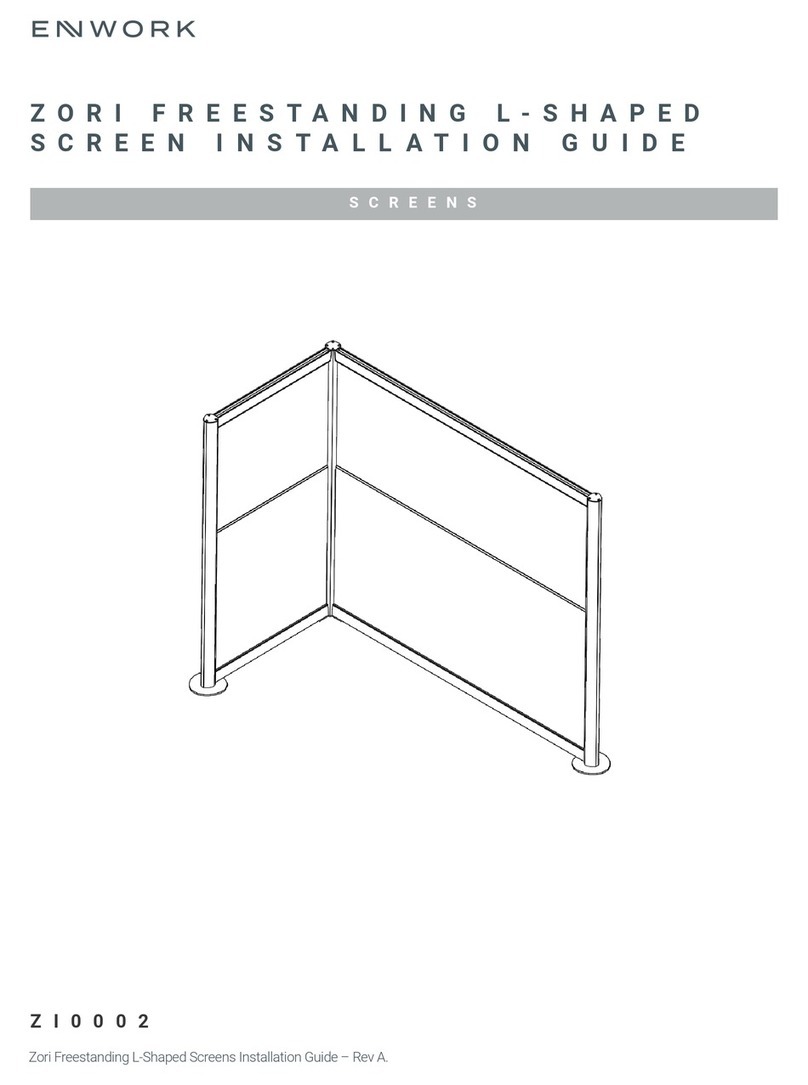
Enwork ZOR User manual

Enwork

Enwork ZOR User manual

Enwork Stealth Service manual

Enwork

Enwork Stealth Service manual
Enwork CONCURRENCE User manual

Enwork

Enwork CONCURRENCE User manual
Enwork Sliding Top Desk User manual

Enwork

Enwork Sliding Top Desk User manual

Enwork eBench Table User manual

Enwork

Enwork eBench Table User manual

Enwork Landing User manual

Enwork

Enwork Landing User manual
Enwork FE Series User manual

Enwork

Enwork FE Series User manual
Enwork Ligouri TI0061 User manual

Enwork

Enwork Ligouri TI0061 User manual
Enwork eBench Table User manual

Enwork

Enwork eBench Table User manual
Enwork TI0023 User manual

Enwork

Enwork TI0023 User manual

Enwork Odyssey User manual

Enwork

Enwork Odyssey User manual
Enwork TI0022 User manual

Enwork

Enwork TI0022 User manual
Enwork Ambition User manual

Enwork

Enwork Ambition User manual

Enwork PROXI User manual

Enwork

Enwork PROXI User manual
Enwork Zori Flip Table User manual

Enwork

Enwork Zori Flip Table User manual
Enwork IMPRESSION FLIP TABLE User manual
Enwork

Enwork IMPRESSION FLIP TABLE User manual

Enwork LANDING XNEL363672-002 User manual
Enwork

Enwork LANDING XNEL363672-002 User manual

Enwork Landing User manual

Enwork

Enwork Landing User manual
Enwork Equilibrium User manual

Enwork

Enwork Equilibrium User manual
Enwork Solano VT2 User manual

Enwork

Enwork Solano VT2 User manual

Enwork Stealth User manual

Enwork

Enwork Stealth User manual

Enwork Sensation Flip Table User manual

Enwork

Enwork Sensation Flip Table User manual

Enwork SKYLINE User manual

Enwork

Enwork SKYLINE User manual

Enwork ALKALIGN TABLE TI0042 User manual

Enwork

Enwork ALKALIGN TABLE TI0042 User manual

Popular Indoor Furnishing manuals by other brands
Furinno FNBJ-22080 Assembly instruction

Furinno

Furinno FNBJ-22080 Assembly instruction

Costway HV10075 user manual

Costway

Costway HV10075 user manual

Sauder Shoal Creek 418658 Instruction booklet

Sauder

Sauder Shoal Creek 418658 Instruction booklet

Cooper Lighting Shaper 1240 Series Specification sheet

Cooper Lighting

Cooper Lighting Shaper 1240 Series Specification sheet

John Lewis 803/40901 instructions for future use

John Lewis

John Lewis 803/40901 instructions for future use

Furinno 14054 Assembly instruction

Furinno

Furinno 14054 Assembly instruction

Allen + Roth 2808427 Quick reference guide

Allen + Roth

Allen + Roth 2808427 Quick reference guide

Whittier Wood 1877GBCHa Assembly instructions

Whittier Wood

Whittier Wood 1877GBCHa Assembly instructions

Twoey inside 6900 quick start guide

Twoey inside

Twoey inside 6900 quick start guide

BUT NEXT3 4894223202329 Assembly instructions

BUT

BUT NEXT3 4894223202329 Assembly instructions

BDI TANAMI BAR 7120 instruction manual

BDI

BDI TANAMI BAR 7120 instruction manual

KITALY Stone Assembly instructions

KITALY

KITALY Stone Assembly instructions

Anova D1110 Assembly instructions

Anova

Anova D1110 Assembly instructions
Craft+Main BALI CNO-01281 Assembly instructions
Craft+Main

Craft+Main BALI CNO-01281 Assembly instructions

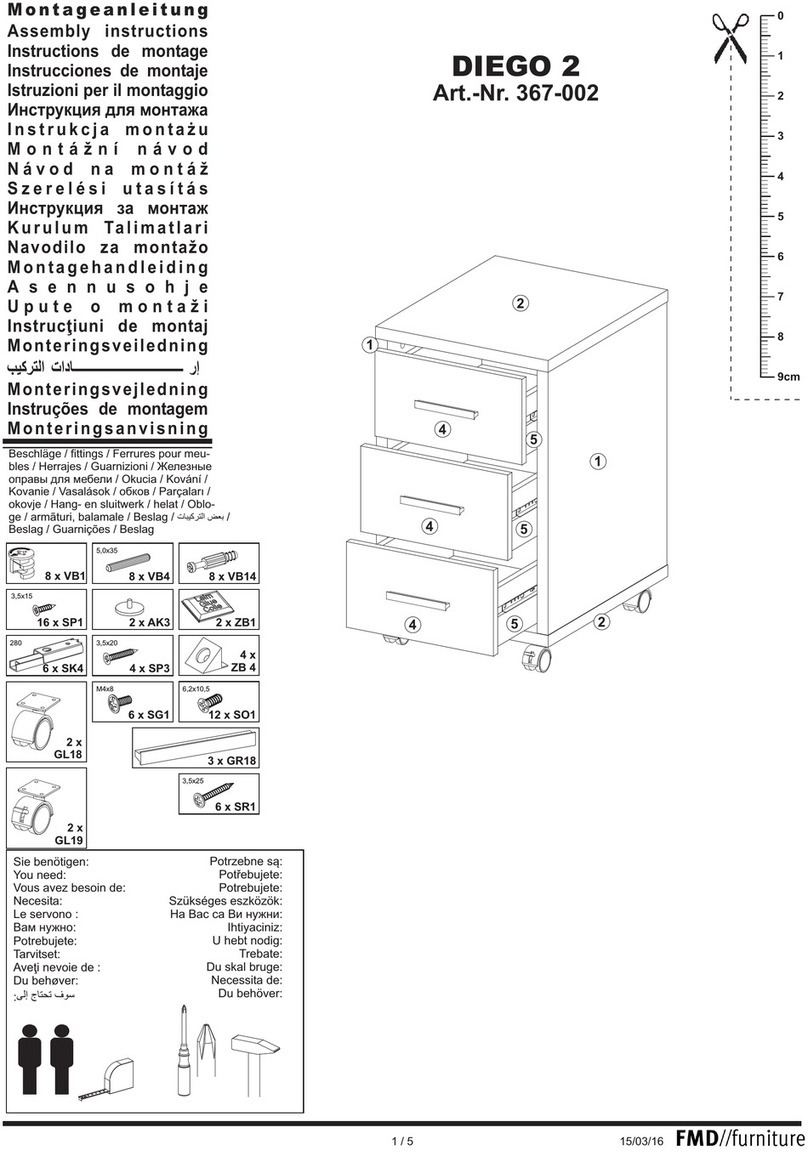
FMD Furniture DIEGO 2 367-002 Assembly instructions

FMD Furniture

FMD Furniture DIEGO 2 367-002 Assembly instructions

World Market Segovia SKU-582741 Assembly instructions

World Market

World Market Segovia SKU-582741 Assembly instructions

Forte JKZT121L Assembling Instruction

Forte

Forte JKZT121L Assembling Instruction

Pegasus Danbury DBCA4222 Specification sheet

Pegasus

Pegasus Danbury DBCA4222 Specification sheet

manuals.online logo
manuals.online logoBrands
  • About & Mission
  • Contact us
  • Privacy Policy
  • Terms and Conditions

Copyright 2025 Manuals.Online. All Rights Reserved.