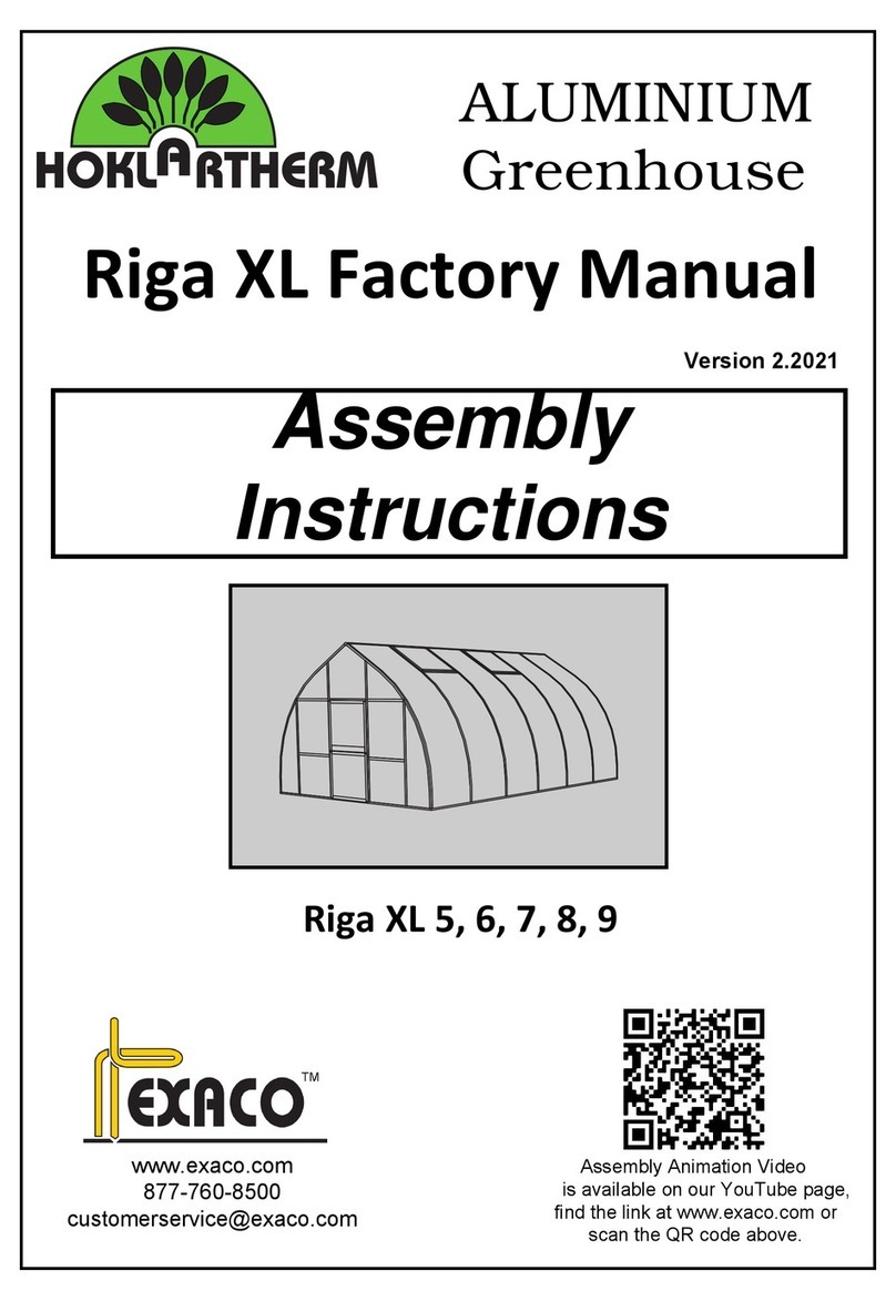
Exaco Riga XL VI User manual

Riga XL VI
Assembly Guide
January 31, 2013
Exaco Trading Co.
10203 Metropolitan Drive
Austin, Texas 78758-4944
512-407-8500

2
ABOUT THIS DOCUMENT
This document is an Assembly Guide intended for persons who
have a moderate level of experience building small structures.
It is specific to the six-meter Riga XL VI, but can be applied to
Riga XL models of other lengths. If you are an experienced Riga
greenhouse builder, this is the guide for you. Keep these pages
for reference as you proceed with your assembly project.
If you lack experience, or if you wish to approach building your
Riga XL with all uncertainties resolved, you should download
and study the Riga XL Owner’s Reference Manual. It is
enhanced for online reading and is packed with valuable
information that can be otherwise gained only from experience.
Once you understand the details you can refer to the Assembly
Guide throughout your project to assure a trouble-free
experience and optimum results.
Download the Riga XL Owner’s Reference Manual
http://exaco.com/rigamanual/RigaXLRefManual.pdf

3
Table of Contents
ABOUT THIS DOCUMENT .............................................................................................................................. 2
Download the Riga XL Owner’s Reference Manual .............................................................................. 2
INTRODUCTION............................................................................................................................................. 6
Welcome to the Exciting World of Riga XL Ownership............................................................................. 6
Riga XL Models.......................................................................................................................................... 6
Available Options ...................................................................................................................................... 6
Tools and Additional Materials You Will Need ......................................................................................... 7
Mandatory tools and materials............................................................................................................. 7
Recommended additional tools............................................................................................................ 7
Recommended additional materials..................................................................................................... 7
Tools and materials included in the Riga XL Essentials Kit.................................................................... 7
RECEIVING INSPECTION ................................................................................................................................ 8
Take Inventory .......................................................................................................................................... 8
Box 3: Small Parts..................................................................................................................................... 9
Box 2: Window and Door Profiles .......................................................................................................... 13
Box 1: Profiles for Gables ....................................................................................................................... 14
Box 4: Long Profiles................................................................................................................................ 15
Arch Bundles 1 and 2: Curved Profiles................................................................................................... 16
Glazing Bundles 1 and 2 .......................................................................................................................... 17
Options and Accessories .........................................................................................................................19
Aluminum foundation frame .............................................................................................................. 19
Shelf kit ............................................................................................................................................... 20
Door extension kit............................................................................................................................... 20
Adjustable hanger accessory kit?........................................................................................................ 20
SITE PREPARATION...................................................................................................................................... 21
Foundation.............................................................................................................................................. 21
Greenhouse dimensions .....................................................................................................................21
Substrate elevation ............................................................................................................................. 21
Pier and beam foundation ..................................................................................................................21
Stem wall foundation.......................................................................................................................... 22
Concrete slab foundation.................................................................................................................... 22
Aluminum foundation frame .............................................................................................................. 23
Isolation membrane................................................................................................................................ 23

4
STEP-BY-STEP ASSEMBLY GUIDE................................................................................................................. 24
Summary of Assembly Steps................................................................................................................... 24
Steps 1 and 2: Assemble the roof windows and doors...................................................................... 24
Steps 3 through 10: Build the first gable............................................................................................ 24
Steps 11 through 16: Build the roof and side walls. ..........................................................................24
Step 17: Build the second gable and join it to the side walls.............................................................24
Step 18: Anchor the greenhouse to its foundation. ..........................................................................24
Steps 19 through 23: Finish the interior and exterior........................................................................ 24
Locations of Frame Components ............................................................................................................25
Step 1 Roof Windows............................................................................................................................. 26
Step 2a Upper Doors.............................................................................................................................. 27
Step 2b Lower Doors.............................................................................................................................. 28
Step 3 Gable Floor Profile and Vertical Door Profiles ............................................................................29
Step 4 Lower 980 x 944 mm Glazing Panels (1 & 2 of 4)........................................................................ 30
Step 5 Lower Crossbars (1 & 2 of 5m)....................................................................................................31
Step 6 T-connectors and Upper 980 by 944 mm Glazing Panels (3 & 4 of 4) ........................................32
Step 7 Vertical Middle Profiles............................................................................................................... 33
Step 8 T-connectors and Upper Crossbars (3, 4, & 5 of 5).....................................................................34
Step 9 Curved & 5-sided Glazing, Straight, K, and Slanted T-connectors .............................................. 35
Step 10 Edge Stay Bars with Pressed-on Plastic Corner Connectors ..................................................... 36
Step 11 Load Screws in the Curved Center Profiles............................................................................... 37
Step 12 Prepare the Floor Profiles, Crossbars, and Roof Beam............................................................. 38
Measure and mark the floor profiles and roof beam reinforcement bar........................................... 38
Prepare the side floor profiles ............................................................................................................ 38
Temporarily prepare the south gable floor profile.............................................................................38
Prepare the roof beam reinforcement bar ......................................................................................... 39
Prepare the window opening crossbars ............................................................................................. 39
Step 13 Set the Floor Profiles................................................................................................................. 40
Step 14 Install the North, East, and West Mounting Brackets .............................................................. 41
Step 15 Set the Roof Beam ....................................................................................................................42
Step 16 Assemble the Side Walls ........................................................................................................... 43
Introduction to Step 16....................................................................................................................... 43
The Window Installation Rule............................................................................................................. 43
General instructions for Step 16......................................................................................................... 44

5
Step 17 Assemble and Set the Second Gable ........................................................................................ 50
Step 18 Install the South Gable Mounting Brackets .............................................................................. 51
Step 19 Install the Lateral Supports .......................................................................................................52
Step 20 Install Interior Seals .................................................................................................................. 53
Step 21 Apply Exterior Sealant............................................................................................................... 54
Step 22 Hang the Doors .........................................................................................................................55
Step 23 Install the Window Openers ..................................................................................................... 56
INSTALL OPTIONS........................................................................................................................................ 57
Install the Optional Shelving ................................................................................................................... 57
Install the 500 Millimeter Door Extension Kit......................................................................................... 58
Assemble the Aluminum Foundation Frame .......................................................................................... 59
SUPPLEMENTAL INFORMATION ................................................................................................................. 61
All About Anchoring ................................................................................................................................ 61
About installing mounting brackets.................................................................................................... 61
Reasons to install mounting brackets in Step 14 ................................................................................61
Reasons to defer mounting bracket installation until Step 18 ........................................................... 61
Installing temporary anchors .............................................................................................................. 61
Anchoring to Concrete: A Special Case .................................................................................................. 62
The problem........................................................................................................................................ 62
The solution ........................................................................................................................................ 62
FREQUENTLY ASKED QUESTIONS................................................................................................................ 63
What is the Riga XL Essentials Kit (REK)?................................................................................................ 63
Why are ratcheting cargo straps recommended? ..................................................................................63
Why are additional M6x12 cap screws recommended? ......................................................................... 63
Why would anyone want extra lateral supports?................................................................................... 63
Why UNC ¼-20 cap screws instead of M6 in the windows, and why extras?......................................... 64
Why #10 x ¾ inch pan head and #8 x ¾ inch flat head Phillips screws? .................................................64
Why preload extra M6x16 screws in each edge stay bar?...................................................................... 64
Why must a window’s installation path be free of glazing and vertical profiles? .................................. 64
What is a roof beam fitment tool?.......................................................................................................... 65
What if a roof beam fitment tool is not available?................................................................................. 65
What is a medium modulus neutral cure silicone sealant? ....................................................................66

6
INTRODUCTION
Welcome to the Exciting World of Riga XL Ownership
Congratulations on your wise decision to acquire a Riga XL greenhouse. You have chosen the finest
personal greenhouse available.
This manual will guide you through all aspects of Riga XL ownership with special emphasis on assembly.
Please read it thoroughly, even before you unpack your shipment, and refer to it throughout the
assembly process. If you follow the instructions and use the recommended tools, you should be able to
easily assemble the greenhouse by yourself.
Riga XL Models
All Riga XL models are identical in width and height but there are five different lengths. The model
variations are identified by a Roman numeral suffix equal to the number of 1-meter length sections for
that model.
The Riga XL VI is the standard 6-meter length and is the subject of this manual. Available by special
order are the smaller Riga XL IV and Riga XL V, which are 4 and 5 meter lengths respectively. Also
available by special order are the stretch models Riga XL VII, Riga XL VIII, and Riga XL IX, which are 7, 8,
and 9 meters long respectively.
The models differ only in the lengths of the horizontal side profiles, the number of side glazing panels
and curved center profiles (arches), the number of roof windows and window openers, and the
quantities of supporting fasteners and seals. The horizontal side profiles for all models are one piece
except those of the Riga XL IX which are two pieces spliced near the center. The IX model includes a
robust welded aluminum truss for additional support of the roof beam at the splice.
Available Options
Three options and an accessory kit are manufactured for the Riga XL.
A shelving kit to be installed along one wall.
A door extension kit to lower one door if the greenhouse is built on a stem wall.
An aluminum foundation frame to use if you want your greenhouse at grade level.
Adjustable hanger accessory kit provides attachment points for plant support.
Two shelving kits are required if you want shelving on both sides, and two door extension kits are
required if you want both doors lowered into stem wall openings.

7
Tools and Additional Materials You Will Need
Mandatory tools and materials
8-foot step ladder
#2 Phillips screwdriver
Bubble level 2 to 3 ft. long
Powered screw driver with #2 Phillips bits
Rubber mallet
28 anchor fasteners appropriate for your foundation substrate (must fit 3/8” hole)
Material to erect temporary bracing for the gables and roof beam
Recommended additional tools
10 millimeter socket wrench or nut driver
6-foot step ladder
Work table
At least three sawhorses
Rubber mallet
Industrial quality scissors to cut seal material
At least four clamps such as Irwin “Quick Grip”
Two adjustable hanger accessory kits
Window screen bead roller to help press in window and door seals
10-foot length of ½” EMT electrical metallic tubing (conduit) to use as a window prop
Recommended additional materials
Membrane to isolate the aluminum floor profiles from the foundation substrate
Roll of 1-inch “Scotch blue painter’s tape
Thread lubricant for self-tapping screws (a wax crayon will do)
Additional M6 stainless cap screws of appropriate length for future attachments to profiles
8 tether cables for window uplift restraints
Tools and materials included in the Riga XL Essentials Kit
10 millimeter combination wrench
Metric measuring tape, 6 meters or longer
Two 10.1 fl. ounce tubes of medium modulus neutral cure clear silicone sealant
Roof beam fitment tool
Marking pen, such as Sharpie®
At least two ratcheting cargo straps, 1-inch wide x 20 ft. long with double J-hooks
16 UNC ¼-20 x ¾ inch stainless cap screws with nuts, and 24 ¼ inch stainless flat washers
Stainless self-tapping Phillips pan head screws; four #10 x ¾ inch and four #8 x ¾ inch
Drill bits; one each #31 (0.120 inch) and #27 (0.144 inch) for door holders
Four pieces of double sided mounting tape, ¾ by 2 inch, for door holders
36 M6 x 8 mm stainless cap screws

8
RECEIVING INSPECTION
Your Riga XL came all the way from Germany without damage, but domestic motor freight will expose it
to more serious hazards. Have a camera ready when your Riga XL is delivered and carefully inspect the
packages for damage before the delivery driver leaves. The polycarbonate panels are most vulnerable; a
gentle kiss from a fork lift tine can do serious damage.
Photograph any damage and describe it on both your copy and the driver’s copy of
the Bill of Lading. This evidence will be needed to file an insurance claim.
Immediately notify Exaco Customer Service at (877) 760-8500 or (512) 407-8500.
Take Inventory
One of the most helpful things you can do to make your project go smoothly is to carefully inspect and
inventory the materials in your shipment. This will familiarize you with the parts and give you time to
replace any that are missing or damaged before you start construction. An illustrated check list is
provided in this section to help make inspection easy and accurate. Report any shortages or damage to
Exaco Customer Service within 30 days.
Your Riga XL VI will arrive on a very long pallet. Bound to the pallet are two large flat bundles of glazing,
two curved wrapped bundles, and three long boxes. In addition to the pallet is a very long cardboard
tube containing a fourth long box. If you ordered any accessories you will receive additional boxes or
bundles. Some accessories, such as heaters, ventilators, and solar lights, might be shipped separately.
Start your inspection with Box 3 and continue with Box 2 and then Box 1. Inspect Box 4 last. Then open
and inspect Arch bundles 1 and 2 and finish with the Glazing bundles.
Components are identified by Pos. numbers. The extruded aluminum components are referred to as
profiles. Some of the extruded parts are referred by more specific names, such as edge stay bar,
crossbar, lateral supports, roof beam, and reinforcement bar.

9
Box 3: Small Parts
Box 3 contains the small parts, most of which are fasteners. Several sizes of screws may be mixed in a
single bag. Sort and count them, then put each size in an individual marked bag. Count carefully; extra
screws are rarely provided.
Illustration
Identifier and
description
Quantity expected
and where used
Quantity
received
Pos. 6.7
Hold-down mounting bracket
Not used if assembling on an
optional aluminum
foundation frame.
18
8 for gables, 10 for side walls
Fasten vertical profiles to floor
profiles and anchor all to
foundation
Pos. 100
Plastic corner connector,
black
4
1 at each floor profile corner to
join profiles with edge stay bar
Pos. 101
Straight connector plate
4
Gables, fasten crossbars above
doors
Pos. 102
Slanted T-connector plate
4
Gables, fasten edge stay bars to
vertical door profiles
Pos. 103
T-connector plate
8
Gables, fasten lower crossbars
between vertical door and middle
profiles
Pos. 104
K-connector plate
4
Gables, fasten vertical middle
profiles and crossbars to edge
stay bars
Pos. 105
Floor profile connector
4
Floor profile, connect inside
corners
Pos. 107.12
Set of M6 x 12 mm hex head
cap screw with nut
188
92 for gable connector plates, 16
for gable mounting brackets, 44
for floor profiles, 28 for side wall
arches, 8 for window crossbars
Pos. 107.16
Set of M6 x 16 mm hex head
cap screw with nut
36
8 for gables, 2 for side wall arches,
8 for window crossbars
Pos. 108
M6 flat fender washer
28
Used under M6 nuts that fasten
lateral supports to curved profiles

10
Illustration
Identifier and
description
Quantity expected
and where used
Quantity
received
Pos. 110
Insulation seal, 6 x 8 mm
thick shipped as dual-strand
coil. Separate the strands
and cut lengths to fit.
1 dual-strand coil
Install in gap inside greenhouse
between glazing and floor profile,
20 places.
Pos. 111
Phillips head screw, 4.2 x 13
mm pan head
12
4 for roof beam end cap cover
plates, 8 to fasten gable profiles
to floor profiles
Pos. 112
Phillips head screw, 4.2 x 60
mm flat head
Caution! Do not confuse
with Pos. 142 which is a 4.2
x 50 mm pan head screw.
64
8 on each of 2 top and 2 bottom
doors, 8 on each of 4 roof
windows
Pos. 113
Phillips head screw, 4.8 x 16
mm pan head
16
Fastens floor profile corner
connector covers (Pos. 116) 4
places
Pos. 114
Roof beam end cap cover
plate
2
Covers and retains the roof beam
ends
Pos. 115
Connector plate
NOTE: Might be bundled
with large connector plates,
Pos. 101 through 104.
8
Retains crossbars under roof
windows
Pos. 116
Floor profile corner
connector cover.
NOTE: Might be bundled
with large connector plates,
Pos. 101 through 104.
4
Reinforce floor profile corners
Fasten with 4.8 x 16 mm Phillips
pan head screw (Pos. 113)
Pos. 117
Phillips head self-drilling
screws, 3.5 x 13 mm pan
head
32
Fastens K-connectors & slanted T-
connectors (Pos. 102 & 104) to
edge stay bars
Pos. 126, Pos. 138, Pos. 153
combined
T-seal, cut from coil as
required to fit
1 coil
Weather seal for roof windows
and doors
Pos. 127A
Plastic corner connector,
black, used at upper left and
lower right window and door
corners
14
2 for each of 4 roof windows
2 for each of 2 bottom doors
1 for each of 2 top doors, upper
corners only

11
Illustration
Identifier and
description
Quantity expected
and where used
Quantity
received
Pos. 127B
Plastic corner connector,
black, used at upper right
and lower left window and
door corners
14
2 for each of 4 roof windows
2 for each of 2 bottom doors
1 for each of 2 top doors, upper
corners only
Pos. 135
Hinge set, black
8
2 for each of 2 bottom doors
2 for each of 2 top doors
Pos. 136
Sash lock, black
4
1 for each of 2 bottom doors
1 for each of 2 top doors
Pos. 137
End cap for rectangular tube,
black
4
1 at each end of 2 rectangular
tubes (Pos. 47) on bottom doors
Pos. 139
Phillips head screw, 4.8 x 25
mm flat head
16
Fasten 4 door hinges to each of 2
right vertical door profiles (Pos. 7)
Pos. 140
Phillips head screw, 4.8 x 16
mm flat head
16
Fasten 2 door hinges to each of 4
door frame profiles (Pos. 42 & 45)
Pos. 141
Phillips head screw, 3.5 x 22
mm flat head
8
Fasten 1 sash lock to each of 4
door frame profiles (Pos. 43 & 44)
Pos. 142
Phillips head screw, 4.2 x 50
mm pan head
Caution! Do not confuse
with Pos. 112 which is a 4.2
x 60 mm flat head screw.
8
4 (2 each door) to fasten
rectangular tube (Pos. 47) to
bottom door frame profiles (Pos.
46).
4 (2 each gable) to fasten crossbar
to vertical door profiles
Pos. 143
Glazing block, white, 30mm x
16mm x 4mm
16
2 for each of 4 roof windows
2 for each of 2 top and 2 bottom
doors
Pos. 150
Door lever sets, 8 boxed
components
2
Door lever sets for each of 2 top
doors

12
Illustration
Identifier and
description
Quantity expected
and where used
Quantity
received
Pos. 158
Two-part door holder set
2
1 set at each of 2 top doors
Pos. 159
Phillips head screws, 3.5 x 16
mm pan head
8
Intended to fasten door holder
sets (Pos. 158) but these screws
are incorrect. Instead use #10 x ¾
inch Phillips pan head for the
male part and #8 x ¾ inch Phillips
flat head for the female part.
(No Pos. assigned)
Automatic window opener
assembly
4
1 opener for each of 4 windows

13
Box 2: Window and Door Profiles
Box 2 contains the profiles to construct four roof windows and two each upper and lower Dutch doors.
All of the window and door profiles except Pos. 43 and Pos. 47 are cut from the same extrusion, differing
only in length and borings for hinges or other attachments. Except for Pos. 43 and Pos. 47, the profiles
are conveniently bundled as follows:
Four window bundles, each with two Pos. 34 and two Pos. 35.
Two lower door bundles, each with one Pos. 44, one Pos. 45, one Pos. 46, and one Pos. 48.
Two upper door bundles, each with one Pos. 41 and 1 Pos. 48.
Cross section
Identifier and
description
Quantity expected
and where used
Quantity
received
Pos. 34
Roof window profile, 865
mm long
8
Top and bottom of each of 4 roof
windows
Pos. 35
Roof window profile, 993
mm long
8
Left and right sides of each of 4
roof windows
Pos. 41
Upper door profile, 949 mm
long, edge bored for latch
and sash lock
2
Left side of each of 2 upper doors
Pos. 42
Upper door profile, 949 mm
long, bored for hinges
2
Right side of each of 2 upper
doors
Pos. 44
Lower door profile, left side,
887 mm long, bored for sash
lock
2
Left side of each of 2 lower doors
Pos. 45
Lower door profile, right
side, 887 mm long, bored for
hinges
2
Right side of each of 2 lower
doors
Pos. 46
Lower door profile, top side,
864 mm long, bored to
attach rectangular tube
2
Top of each of 2 lower doors
Pos. 48
Upper and lower door
profile, 864 mm long
4
Top of each of 2 upper doors and
bottom of each of 2 lower doors
Pos. 43
Upper door profile, bottom
side, 864 mm long, bored
for lever set
2
Bottom of each of 2 upper doors
Pos. 47
Rectangular tube, 933 mm
long, 2 holes bored on one
face
2
Attach to Pos. 46 to fill space at
top of each lower door

14
Box 1: Profiles for Gables
Box 1 contains the straight vertical and horizontal profiles used for the two gables, and the crossbars
used beneath the roof windows. All of these profiles are cut from the same extrusion, differing only in
length, end finishing, and borings.
The gable floor profiles are contained in Box 4.
Cross section
Identifier and
description
Quantity expected
and where used
Quantity
received
Pos. 4
Vertical profile, middle left,
1929 mm long, 50° top angle
2
Vertical profile midway between
left side door jamb and right
outside corner of greenhouse
Pos. 5
Vertical profile, middle right,
1929 mm long, 50° top angle
2
Vertical profile midway between
right side door jamb and right
outside corner of greenhouse
Pos. 6
Vertical door profile, left,
2641 mm long, 30° top angle,
bored for 4.2 x 50 mm
crossbar screw (Pos. 142)
2
Vertical profile used as left side
door jamb in each of two gables
Pos. 7
Vertical door profile, right,
2641 mm long, 30° top angle,
bored for 4.2 x 50 mm
crossbar screw (Pos. 142)
and hinges
2
Vertical profile used as right side
door jamb in each of two gables
Pos. 8
Crossbar, 952 mm long,
identical to Pos. 25
10
Five horizontal glazing supports in
each of two gables
Pos. 25
Crossbar, 952 mm long,
identical to Pos. 8
4
Support top edge of side wall
glazing beneath each of 4 roof
windows

15
Box 4: Long Profiles
Box 4 is shipped inside of a heavy cardboard tube for additional protection during shipment. This box
contains the longest straight parts; the floor profiles, the lateral supports, the roof beam, and the roof
beam reinforcement bar.
Cross section
Identifier and
description
Quantity expected
and where used
Quantity
received
Pos. 1
Gable floor profile, 4145 mm
long
2
1 for each of 2 gables, retains
bottom end of all vertical profiles
Pos. 18
Floor profile for side walls,
5903 mm long
2
1 for each of 2 side walls, retains
bottom end of all curved center
profiles (arches)
Pos. 22
Lateral supports, 5960 mm
long
4
2 for each of 2 side walls, these
full length horizontal braces index
the position of the curved center
profiles and provide longitudinal
resistance to wind forces. They
also provide attachment points
for shelving and plant support
systems.
Pos. 28
Roof beam, 6002 mm long
1
Main support beam at
greenhouse ridge, also anchors
top ends of edge stay bars and
curved center profiles (arches)
Pos. 31
Roof beam reinforcement
bar, 5960 mm long (will be
bound to the roof beam)
1
Fortifies the roof beam and
provides M6 cap screw capture
slots to attach plant support
systems

16
Arch Bundles 1 and 2: Curved Profiles
There are two models of curved profiles. The curved center profiles (Pos. 19) form the arched framing
for the side walls, and the edge stay bars (Pos. 2 and 3) form the arches of the gables. The curved center
profiles are all identical, but the edge stay bars come in left and right configurations.
Cross section
viewed from top
Identifier and
description
Quantity expected
and where used
Quantity
received
Pos. 2
Edge stay bar, right side
(also known as right edge
clamp or right gable arch)
2
Right side of each gable as viewed
from outside the greenhouse
Pos. 3
Edge stay bar, left side
(also known as left edge
clamp or left gable arch)
2
Left side of each gable as viewed
from outside the greenhouse
Pos. 19
Curved center profile
(also known as center clamp
or side wall arch)
10
Side walls between the two gables
Dimensions in millimeters of
the edge stay bars and curved
center profiles (arches).
Bottom
Top

17
Glazing Bundles 1 and 2
There are eight shapes of polycarbonate glazing panels, two of which exist in both left and right side
version. All panels are 16 mm thick triple-wall. The illustration is as viewed from outside the
greenhouse, looking at the ultraviolet-protected face.
Do not store glazing where any portion of it will be exposed to direct sunlight.
Illustration
(Not to scale)
Overall dimensions (width x
height) in millimeters
Quantity expected
and where used
Quantity
received
602 x 1922
Curved glazing panel
2
Left outer cell of each gable
602 x 1922
Curved glazing panel
2
Right outer cell of each gable
980 x 727
Curved glazing panel
2
Upper left inner cell in each gable
980 x 727
Curved glazing panel
2
Upper right inner cell in each
gable
980 x 944
8
Four inner cells either side of door
in each gable
980 x 1008
5-sided glazing panel
2
Cell above door in each gable

18
Illustration
(Not to scale)
Overall dimensions (width x
height) in millimeters
Quantity expected
and where used
Quantity
received
888 x 835
4
Top and bottom door panels in
each gable
980 x 3893
8
Side wall bays without roof
windows
980 x 2830
4
Side wall bays with roof windows
888 x 943
4
Roof window panels

19
Options and Accessories
Aluminum foundation frame
Cross section or illustration
Identifier and
description
Quantity expected
and where used
Quantity
received
Pos. 6.1
Foundation frame profile
for gables, 4100 mm long
2
Supports each gable floor
profile
Pos. 6.2
Foundation frame profile
for sides, 5858 mm long
2
Supports each side wall floor
profile
Pos. 6.3
Foundation corner
connector, 40mm x
40mm x 135mm (1 mm
thick)
4
At each corner of the
foundation frame
Pos. 6.4
Hold-down plate
18
Connect each vertical profile
to the foundation frame
Pos. 117
Phillips head self-drilling
screw, 3.5 x 13 mm pan
head
20
Four for each gable floor
profile and six for each side
floor profile to fasten the
profile to the foundation
frame
Pos. 107.12
Set of M6 x 12 mm hex
head cap screw with nut
44
Two to fasten each corner
connector to foundation
profiles (4 places), two to
fasten each hold-down plate
to vertical profile and
foundation frame (18 places)

20
Shelf kit
This is preliminary information will be completed a future release of this manual.
A new style shelf system for Riga greenhouses began shipping in 2012. The suspension chains of the
older system have been replaced by brackets attached to the arches.
Door extension kit
This preliminary information will be completed in a future release of this manual.
A kit is available for a Riga XL built on a stem wall. Use the door extension kit to relocate the doorway
500 millimeters downward for easy entry through the stem wall.
Adjustable hanger accessory kit?
The adjustable hanger accessory kit is an assortment of parts to install hooks
on the roof beam reinforcement bar, or on any of the lateral supports. In fact
the hooks can be installed in the screw capture slot of any profile. A kit
includes parts for five hanging sites.
In addition to hanging things, the components of the hanger kit
can be helpful during assembly.
Table of contents
Other Exaco Greenhouse Kit manuals
Exaco
Exaco Junior Victorian User manual
Exaco
Exaco EOS ROYAL MUR User manual
Exaco
Exaco EOS ROYAL User manual
Exaco
Exaco VI23 User manual
Exaco
Exaco EOS JUNIOR VICTORIAN User manual

Exaco
Exaco VI23 User manual
Exaco
Exaco VI23 User manual

Exaco
Exaco GIGANT User manual
Exaco
Exaco HELIOS/EOS T User manual
Exaco
Exaco EOS Retro SL User manual
Popular Greenhouse Kit manuals by other brands

Vitavia
Vitavia GAIA JUMBO Assembly instructions
Palram
Palram Harmony 6'x4' Assembly instructions
ClearSpan
ClearSpan Storage Master 104598 instruction manual
Sproutwell
Sproutwell GRANGE - 5 Assembly instructions
STC
STC Easy Grow 6x12 Greenhouse Assembly instructions
Growhouse
Growhouse Lean To 6 x 8 Erection and Glazing Instructions
