Exor UniOP eTOP 500 Series User manual

Exor International S.p.A.
MANUGENETOP5xx UniOP
Ver. 1.07
UniOP eTOP Series 500
Operating Instructions
Basic User’s Manual for eTOP Series 500
Touchscreen Products

2
MANUGENETOP5xx UniOP
Operating Instructions
VER 1.07
Copyright © 2011-2013 Exor International S.p.A. – Verona, Italy
Subject to change without notice
The information contained in this document is provided for informational purposes only. While efforts were made
to verify the accuracy of the information contained in this documentation, it is provided “as is” without warranty
of any kind.
Third-party brands and names are the property of their respective owners.
www.uniop.com

3
MANUGENETOP5xx UniOP
Operating Instructions
VER 1.07
Table of Contents
Introduction.............................................................................................................................................4
Safety Guide...........................................................................................................................................5
1 Product Overview ................................................................................................................................6
2Standards and Approvals ....................................................................................................................7
3 Technical Specifications ......................................................................................................................8
4Technical Data ...................................................................................................................................10
4.1 Dimensions.....................................................................................................................................14
4.2 Installation Environment .................................................................................................................16
4.3 Installation Procedure.....................................................................................................................17
5Connections.......................................................................................................................................18
5.1 Serial Port.......................................................................................................................................20
5.2 Ethernet Port ..................................................................................................................................21
5.3 Optional plugin module...................................................................................................................22
6Power Supply, Grounding and Shielding ...........................................................................................24
7Battery ...............................................................................................................................................25
8Cleaning Faceplates..........................................................................................................................26
9Getting Started ..................................................................................................................................26
10 System Settings...............................................................................................................................27
11 LED Indicator on Front Panel ..........................................................................................................29
12 Unpacking and Packing Instructions ...............................................................................................30
Table of Contents

4
MANUGENETOP5xx UniOP
Operating Instructions
VER 1.07
Introduction
The operational guidelines described below is information which relates to the device, installation, tran-
sportation, storage, assembly, use and maintenance.
This Operating Instruction describes the main features of the UniOP operator panels. The Manual refers
to the following models:
eTOP504 Operator interface with TFT color 4.3” display touchscreen
eTOP506 Operator interface with TFT color 5.7” display touchscreen
eTOP507 Operator interface with TFT color 7” widescreen display touchscreen
eTOP510 Operator interface with TFT color 10.4” display touchscreen
eTOP512 Operator interface with TFT color 12.1” display touchscreen
eTOP513 Operator interface with TFT color 13.3” widescreen display touchscreen
eTOP515 Operator interface with TFT color 15” display touchscreen
Introduction

5
MANUGENETOP5xx UniOP
Operating Instructions
VER 1.07
Safety Guide
The manual contains safety standards that must be respected for the personal safety and to avoid damage.
Indications of attention are divided into three levels of severity:
DANGER: indicates a failure to observe safety rules and such failure may cause death or serious injuries.
ATTENTION: indicates a failure to observe safety rules and that deficiency may cause damage.
CAUTION: indicates a failure to observe safety rules and that deficiency may cause defects to the
equipment or inconsistencies.
CAUTION
ATTENTION
DANGER
E
!
!
Safety Guide

6
MANUGENETOP5xx UniOP
Operating Instructions
VER 1.07
1 Product Overview
The UniOP eTOP Series 500 HMI products combine state-of-the-art features and top performance
with an oustanding design. They are the ideal choice for all demanding HMI applications including
factory and building automation.
The eTOP Series 500 HMI panels have been designed to run the JMobile software.
• JMobile runtime included. Full compatibility with JMobile Studio.
• Full vector graphic support. Native support of SVG graphic objects. Trasparency and alpha
blending.
• Full object dynamics: control visibility and transparency, move, resize, rotate any object on screen.
Change properties of basic and complex objects.
• TrueType fonts.
• Multilanguage applications. Easily create and manage your applications in multiple languages to
meet global requirements. Far East languages are supported. Tools available in JMobile Studio
support easy third-party translations and help reducing development and maintenance costs of the
application.
• Data display in numerical, text, bargraph, analog gauges and graphic image formats.
•Rich set of state-of-the-art HMI features: data acquisition, alarm handling, scheduler and timed
actions (daily and weekly schedulers, exception dates), recipes, users and passwords, RSS feeds,
rotating menus.
• Includes support for a wide range of communication drivers for Factory systems.
• Multiple drivers communication capability.
• Remote monitoring and control. Client-Server functionality.
• Off-line simulation with JMobile Studio.
• Powerful scripting language for automating HMI applications. Script debugging improves efficiency
in application development.
• Rich gallery of vector symbols and objects.
• Project templates.
• Optional plug-in modules for fieldbus systems, I/O and controllers.
Product Overview

7
MANUGENETOP5xx UniOP
Operating Instructions
VER 1.07
2 Standards and Approvals
The products have been designed for use in an industrial environment in compliance with the 2004/108/
EC EMC Directive.
The products have been designed in compliance with:
EN 61000-6-4 EN 55011 Class A
EN 61000-6-2 EN 61000-4-2
EN 61000-4-3
EN 61000-4-4
EN 61000-4-5
EN 61000-4-6
The installation of these devices into the residential, commercial and light-industrial environments is allo-
wed only in the case that special in measures are taken in order to ensure conformity to EN 61000-6-3.
The products are in compliance with the Restrictions on Certain Hazardous Substances (RoHS) Directive
2002/95/EC
In compliance with the above regulations the products are CE marked.
Product Identification
The product may be identified through a plate attached to the rear cover. You will have to know the type
of unit you are using for correct usage of the information contained in the guide.
An example of this plate is shown in the figure below:
eTOP504 product model name
ETOP504U101 product part number
05/11 month/year of production
09994847559 serial number
040100A01000000 version id of the product
Standards and Approvals

8
MANUGENETOP5xx UniOP
Operating Instructions
VER 1.07
3 Technical Specifications
Touch screen technology Resistive
Back-up battery 3V 50mAh Lithium, rechargeable, not user-replaceable,
model VL2330.
Fuse Automatic
Serial Port RS-232, RS-485, RS-422 software configurable
User memory Flash 128Mb for eTOP504, 506, 507
Flash 256Mb for eTOP510, 512, 513, 515
Recipe memory Flash
Hardware clock Clock/Calendar with back-up battery
Accuracy RTC (at 25°C) <100ppm
Environmental conditions
Operating temperature (surrounding 0 ÷ +50°C EN60068-2-14
air temperature)
Storage temperature -20 ÷ +70°C EN60068-2-14
Operating and storage humidity 5 ÷ 85 % RH not-condensing EN60068-2-30
Vibrations 5 ÷ 9 Hz, 7 mm p-p EN60068-2-6
9 ÷ 150 Hz, 1 g
Shock ± 50 g, 11 ms, 3 pulses per axis EN60068-2-27
Protection class IP66 front panel * EN 60529
* The front face of the UniOP unit, installed in a solid panel, has been tested using conditions equivalent
to the standards shown in the “Environmental conditions”. Even though the level of resistance UniOP
unit is equivalent to these standards, oils that should have no effect on the UniOP can possibly harm
the unit. This can occur in areas where either vaporized oils are present, or where low viscosity cutting
oil are allowed to adhere to the unit for long periods of time. If the front face protection sheet on the
UniOP becomes peeled off, these conditions can lead to the ingress of oil into the UniOP and separate
protection measures are suggested.
If the installation gasket is used for a long period of time, or if the unit and its gasket are removed from
the panel, the original level of the protection cannot be guaranteed.
Standards and Approvals

9
MANUGENETOP5xx UniOP
Operating Instructions
VER 1.07
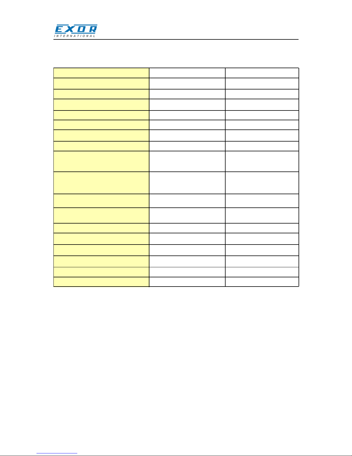
Immunity to conducted disturbances
inducted by radiofrequency field 0.15 ÷ 80 MHz, 10V EN 61000-4-6
Voltage dips, short interruptions and
voltage variations immunity test Port: AC mains; Level:
100% duration: 1 cycle and 250 cycles (50Hz);
40% duration: 10 cycles (50Hz);
70% duration: 25 cycles (50Hz);
Phase: 0°-180°
Test executed on the 230Vac side of the Exor International S.p.A. Power Supply EN 61000-4-11
Standards and Approvals
Durability information
Backlight service life 40000 Hrs. or more
(LED type) (Time of continuos operation until the brightness of the
backlight reaches 50% of the rated value when the
sorrounding air temperature is 25°C) - see Note 1
Front foil 10 years if the surrounding air temperature is 25°C
(without directly exposure to
sunlight or UV ray)
UV Resistance Indoor applications: After 300 hours cycled humidity in
QUV accelerated weathering, some yellowing and
brittleness may be present. - see Note 2.
Touch screen reliability > 1 milion operations
Note 1: Extended use in environments where the surrounding air temperature is 40°C or higher may
degrade backlight quality/reliability/durability.
Note 2: Solvent resistance:
Contact for 1/2 hour at 21°C, No visible effect: Acetone, Butyl Cellosolve, Cyclohexanone, Ethyl Acetate,
Hexane, Isopropyl Alcohol, MEK, Methylene Chloride, Toluene, Xylene
Contact for 24 hours at 49°C, No visible effect: Coffee, Ketchup, Lemon Juice, Mustard (slight yellow
stain), Tea, Tomato juice.
Electromagnetic Compatibility (EMC)
Radiated disturbance test Class A EN 55011
Electrostatic discharge immunity test 8 kV (air electrostatic discharge) EN 61000-4-2
4 kV (contact electrostatic discharge)
Radiated, radio-frequency, 80 MHz ÷ 1 GHz, 10V/m EN 61000-4-3
electromagnetic field immunity test 1,4 GHz ÷ 2 GHz, 3 V/m
2 GHz ÷ 2.7 GHz, 1 V/m
Burst immunity test ± 2 KV dc power port EN 61000-4-4
± 1 KV signal line
Surge immunity test ± 0,5 KV dc power port (line to earth) EN 61000-4-5
± 0,5 KV dc power port (line to line)
± 1 KV signal line (line to earth)

10
MANUGENETOP5xx UniOP
Operating Instructions
VER 1.07
Model eTOP504 eTOP506
Display / Backlight TFT Color / LED TFT Color / LED
Colors 64K 64K
Resolution 480X272 320x240
Diagonal (inches) 4.3” 5.7”
Dimming yes yes
User memory flash 128MB 128MB
SD card slot yes yes
Recipe memory Yes. Flash memory storage Yes. Flash memory storage
limited only by available limited only by available
memory memory
Serial Port RS-232,RS-485 RS-232,RS-485
RS-422 DB9 female RS-422 DB9 female
software configurable software configurable
Ethernet port 2 10/100 Mbit with integrated 2 10/100 Mbit with integrated
switch switch
USB port 1 Host interface 2 Host interface, 1 version 2.0,
version 2.0 and 1.1 1 version 2.0 and 1.1
Expansion slot 1 Optional Plugin 2 Optional Plugin
Battery rechargeable rechargeable
Real Time Clock yes yes
Voltage 10-32Vdc (*) 10-32Vdc (*)
Current rating (at 24VDC) 0.4A 0.65A
Weight 1 Kg 1 Kg
4 Technical Data
Technical Data
(*) For applications requiring compliance with EN 61131-2 and specifically in reference to 10 ms voltage dips, the
minimum power supply voltage is 18Vdc,

11
MANUGENETOP5xx UniOP
Operating Instructions
VER 1.07
Model eTOP507 eTOP510
Display / Backlight TFT Color / LED TFT Color / LED
Colors 64K 64K
Resolution 800X480 800x600
Diagonal (inches) 7” widescreen 10.4”
Dimming yes yes
User memory flash 128MB 256MB
SD card slot yes yes
Recipe memory Yes. Flash memory storage Yes. Flash memory storage
limited only by available limited only by available
memory memory
Serial Port RS-232,RS-485 RS-232,RS-485
RS-422 DB9 female RS-422 DB9 female
software configurable software configurable
Ethernet port 2 10/100 Mbit with integrated 2 10/100 Mbit with integrated
switch switch
USB port 2 Host interface, 1 version 2.0, 2 Host interface, 1 version 2.0,
1 version 2.0 and 1.1 1 version 2.0 and 1.1
Expansion slot 2 Optional Plugin 2 Optional Plugin
Battery rechargeable rechargeable
Real Time Clock yes yes
Voltage 10-32Vdc (*) 10-32Vdc (*)
Current rating (at 24VDC) 0.7A 1 A
Weight 1 Kg 2.1 Kg
Technical Data
(*) For applications requiring compliance with EN 61131-2 and specifically in reference to 10 ms voltage dips, the
minimum power supply voltage is 18Vdc

12
MANUGENETOP5xx UniOP
Operating Instructions
VER 1.07
Model eTOP512 eTOP513
Display / Backlight TFT Color / LED TFT Color / LED
Colors 64K 64K
Resolution 800X600 1280x800
Diagonal (inches) 12.1” 13.3” widescreen
Dimming yes yes
User memory flash 256MB 256MB
SD card slot yes yes
Recipe memory Yes. Flash memory storage Yes. Flash memory storage
limited only by available limited only by available
memory memory
Serial Port RS-232,RS-485 RS-232,RS-485
RS-422 DB9 female RS-422 DB9 female
software configurable software configurable
Ethernet port 2 10/100 Mbit with integrated 2 10/100 Mbit with integrated
switch switch
USB port 2 Host interface, 1 version 2.0, 2 Host interface, 1 version 2.0,
1 version 2.0 and 1.1 1 version 2.0 and 1.1
Expansion slot 2 Optional Plugin 2 Optional Plugin
Battery rechargeable rechargeable
Real Time Clock yes yes
Voltage 10-32Vdc (*) 10-32Vdc (*)
Current rating (at 24VDC) 1.2A 1.2A
Weight 2.8 Kg 2.8 Kg
Technical Data
(*) For applications requiring compliance with EN 61131-2 and specifically in reference to 10 ms voltage dips, the
minimum power supply voltage is 18Vdc.

13
MANUGENETOP5xx UniOP
Operating Instructions
VER 1.07
Technical Data
Model eTOP515
Display / Backlight TFT Color / LED
Colors 64K
Resolution 1024X768
Diagonal (inches) 15”
Dimming yes
User memory flash 256MB
SD card slot yes
Recipe memory Yes. Flash memory storage
limited only by available
memory
Serial Port RS-232,RS-485
RS-422
software configurable
Ethernet port 2 10/100 Mbit with integrated
switch
USB port 2 Host interface, 1 version 2.0,
1 version 2.0 and 1.1
Expansion slot 2 Optional Plugin
Battery rechargeable
Real Time Clock yes
Voltage 10-32Vdc (*)
Current rating (at 24VDC) 1.40A
Weight 3.5 Kg
(*) For applications requiring compliance with EN 61131-2 and specifically in reference to 10 ms voltage dips, the
minimum power supply voltage is 18Vdc,

14
MANUGENETOP5xx UniOP
Operating Instructions
VER 1.07
4.1 Dimensions
Technical Data
eTOP504
MODEL A B C D E F
149mm/5.86” 109mm/4.29” 136mm/5.35” 96mm/3.78” 56mm/2.40” 4mm/0.16”
Cut out

15
MANUGENETOP5xx UniOP
Operating Instructions
VER 1.07
Technical Data
Cut out
eTOP506
eTOP507
eTOP510
eTOP512
eTOP513
eTOP515
MODEL A B C D E F
187mm/7.36”
187mm/7.36”
287mm/11.3”
336mm/13.22”
336mm/13.22”
392mm/15.43”
147mm/5.79”
147mm/5.79”
232mm/9.13”
267mm/10.51”
267mm/10.51”
307mm/12.08”
176mm/6.90”
176mm/6.90”
276mm/10.86”
326mm/12.83”
326mm/12.83”
381mm/15”
136mm/5.35”
136mm/5.35”
221mm/8.70”
256mm/10.07”
256mm/10.07”
296mm/11.65”
47mm/1.85”
47mm/1.85”
56mm/2.20”
56mm/2.20”
56mm/2.20”
60mm/2.36”
4mm/0.16”
4mm/0.16”
4mm/0.16”
4mm/0.16”
4mm/0.16”
4mm/0.16”

16
MANUGENETOP5xx UniOP
Operating Instructions
VER 1.07
4.2 Installation Environment
The equipment is not intended for continuous exposure to direct sunlight.
This might accelerate the aging process of the front panel film.
The equipment is not intended for installation in contact with corrosive chemical compounds. Check the
resistance of the front panel film to a specific compound before installation.
Do not use tools of any kind (screwdrivers, etc.) to operate the touch screen of the panel.
In order to meet the front panel protection classifications, proper installation procedure must be followed:
•the borders of the cutout must be flat
•screw up each fixing screw until the plastic bezel corner get in contact with the panel.
•the cutout for the panel must be of the dimensions indicated in this manual.
The IP66 is guaranteed only if:
• max deviation from the plane surface to the cut-out: O0.5mm
•thickness of the case where is mounted the equipment: from 1,5mm to 6mm
•max surface roughness where the gasket is applied: O120 um
Applying the gasket
The gasket should be applied on the rear of the frame.
Fig. 4.1: eTOP504, eTOP506,
eTOP507
A. Gasket
B. Installation cut-out
Technical Data
Fig. 4.2: eTOP510, eTOP512,
eTOP513, eTOP515

17
MANUGENETOP5xx UniOP
Operating Instructions
VER 1.07
4.3 Installation Procedure
Place the fixing brackets as shown in figure (Fig. 4.3).
Fig. 4.3
CAUTION
Screw each fixing screw until the bezel corner gets in contact with the panel.
E
Technical Data

18
MANUGENETOP5xx UniOP
Operating Instructions
VER 1.07
5 Connections
1. Serial Port
2. 2x Ethernet Port
3. USB Port
4. Power Supply
5. Expansion slot for Plugin module
6. SD Card Slot
Fig. 5.1
Connections
eTOP504

19
MANUGENETOP5xx UniOP
Operating Instructions
VER 1.07
1. Serial Port
2. 2x Ethernet Port
3. 2x USB Port
4. Power Supply
5. 2x Expansion slot for Plugin module
6. SD Card Slot
Fig. 5.2
Connections
eTOP5xx

20
MANUGENETOP5xx UniOP
Operating Instructions
VER 1.07
5.1 Serial Port
The serial port is used to communicate with the PLC or with another type of controller.
Different electrical standards are available for the signals in the PLC port connector: RS-232, RS-422,
RS-485.
Pin Description
1 GND
2
3 CHA-
4 CHB-
5
6 +5V output
7 CHB+
8 CHA+
9
The serial port is software programmable. Make sure you select the appropriate
interface in the programming software.
The communication cable must be chosen for the type of device being connected.
Connections
SERIAL PORT
Pin Description
1 GND
2
3 TX
4 RX
5
6 +5V output
7 CTS
8 RTS
9
RS-232 RS-422, RS-485
To operate in RS485 pins 4-3 and
8-7 must be connected externally.
Other manuals for UniOP eTOP 500 Series
2
Table of contents
Other Exor Touchscreen manuals

Exor
Exor UniOP eTOP 500 Series User manual

Exor
Exor eX700M Series User manual

Exor
Exor JSmart700M Series User manual

Exor
Exor eX710G User manual

Exor
Exor JSmart 710 User manual

Exor
Exor eTOP 300 Series User manual

Exor
Exor eTOP605 User manual

Exor
Exor eTOP605 User manual

Exor
Exor JSmart705 User manual

Exor
Exor eTOP-MON User manual