manuals.online logo
Brands
  1. Home
  2. •
  3. Brands
  4. •
  5. FARFISA INTERCOMS
  6. •
  7. Intercom System
  8. •
  9. FARFISA INTERCOMS PL24S User manual

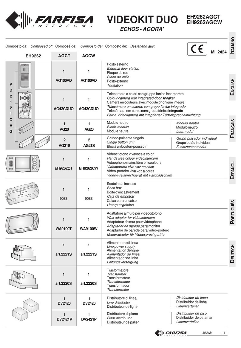
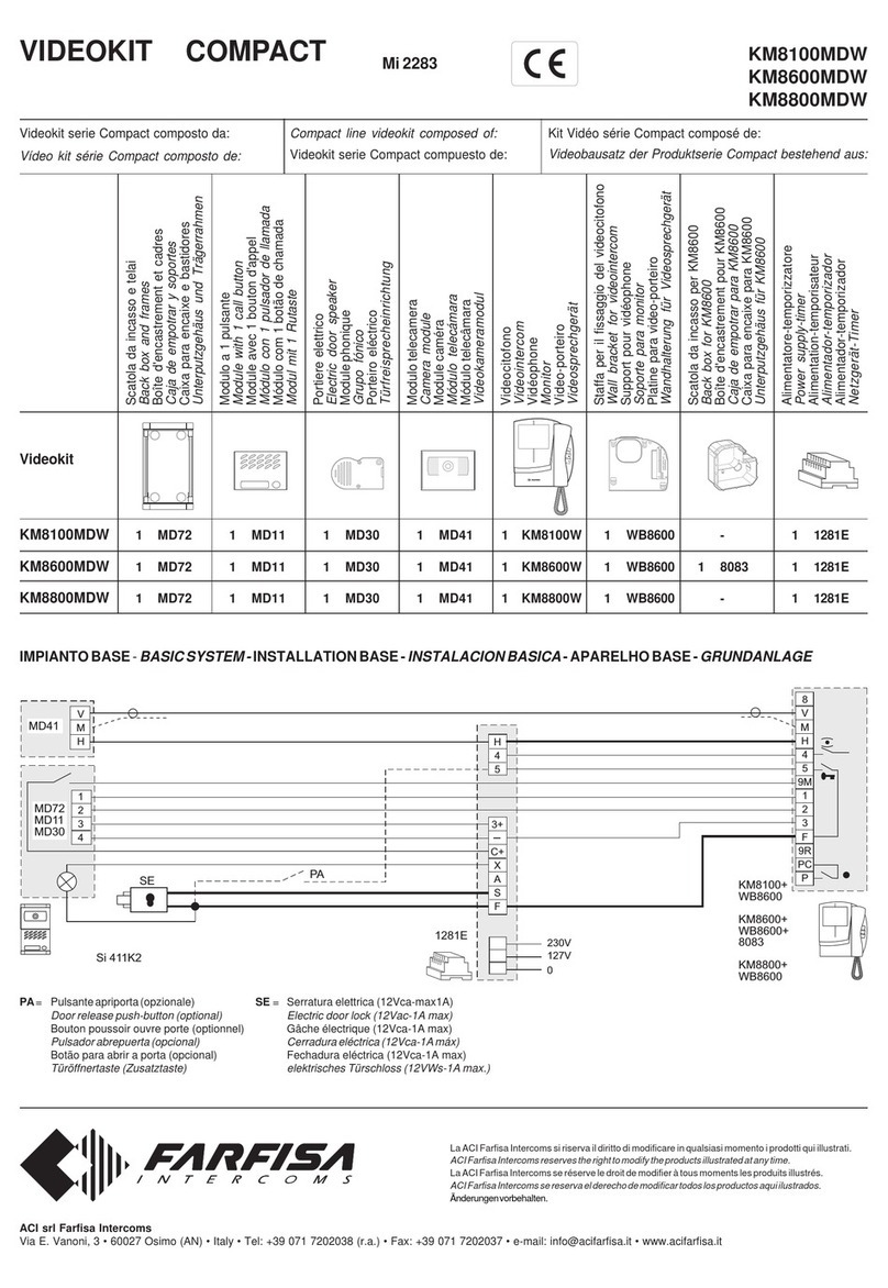
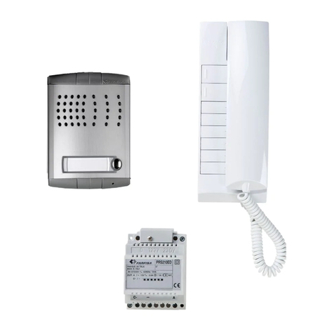
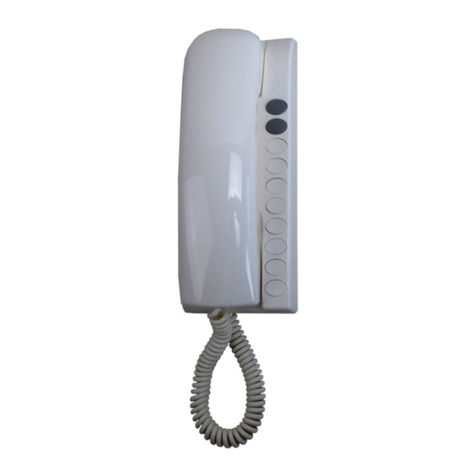
FARFISA INTERCOMS PL24S User manual

ITALIANOENGLISHFRANÇAISESPAÑOLPORTUGUÊSDEUTSCH
Mi 2376
1
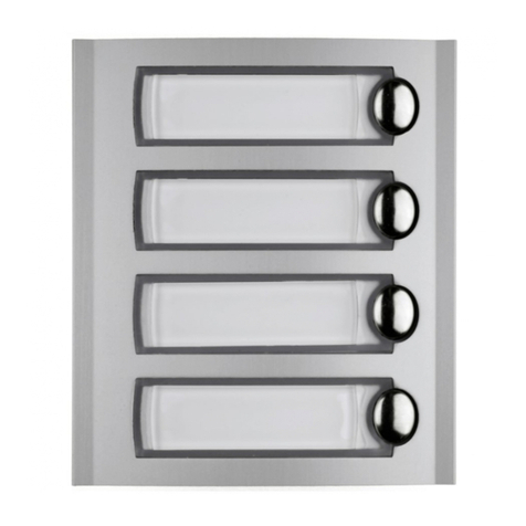
MODULI PULSANTI SERIE
PROFILOCONDECODIFICAIN-
TEGRATA PER SISTEMI DIGI-
TALI
Tramiteilcollegamentoconunopportu-
no codificatore digitale permette di in-
viare chiamate nei sistemi digitali
Farfisa.
Morsetti
A+ ingresso tensione alternata o conti-
nuaperLedillumina-cartellini(13Vca/
cc-80mA)
A- ingressotensionealternataomassa
perLedillumina-cartellini
Art.
PL24S
E
MÓDULOS PULSADORES
SERIE PROFILO CON DESCO-
DIFICACIÓN INTEGRADA
PARA SISTEMAS DIGITALES
Una vez conectados a través de un
adecuado codificador digital permiten
enviarllamadasalossistemasdigitales
Farfisa.
Bornes
A+entrada tensión alterna o continua
para los LEDs que iluminan los
tarjeteros (13Vca/cc-80mA)
A- entradatensiónalternaomasapara
losLEDsqueiluminanlostarjeteros
PROFILO PUSH-BUTTON
MODULES WITH INTEGRA-
TED ENDECODING BOARD
FOR DIGITAL SYSTEMS
Connected with a digital encoder the
modules allow to send calls in Farfisa
digital systems.
Terminals
A+AC or DC power supply input for
name-plateLed(13Vacordc-80mA)
A- ACpowersupplyorgroundinputfor
name-plate Led
MODULES BOUTONS-
POUSSOIRS SÉRIE PROFILO
AVEC DÉCODAGE INTÉGRÉ
POUR SYSTÈMES DIGITAUX
Laconnexionàuncodeurdigitalprévuà
cet effet permet d’adresser des appels
danslessystèmesdigitauxFarfisa.
Bornes
A+ entrée courant alternatif ou continu
pour Led rétro-éclairage étiquettes
porte-noms(13Vca/cc-80mA)
A- entrée courant alternatif ou masse
pour Led rétro-éclairage étiquettes
porte-noms
MÓDULOS DE BOTÕES
SÉRIE PROFILO COM DECO-
DIFICAÇÃOINTEGRADAPARA
SISTEMAS DIGITAIS
Através da coligação com um
codificador digital, é possível enviar
chamadasnossistemasdigitaisFarfisa.
Terminais
A+ ingressotensãoalternadaparaLed
ilumina-cartõezinhos (13Vca/cc-
80mA)
A- ingressotensãoalternadaoumassa
paraLedilumina-cartõezinhos
TASTENMODULE DER
SERIE PROFILO MIT
TASTENKODIERUNG FÜR
BUSSYSTEME
Für den Anschluss an analogen
Steuereinheiten um Anrufe in einem
Farfisa Bussystem zu tätigen.
Klemmen
A+Stromversorgung für
Namensschildbeleuchtung LED
(13Vac/dc,80mA)
A- Masse für Namensschild-
beleuchtung LED
Mi 2376/1
Art.
PL228S
Cod. 52704030
Smaltire il dispositivo secondo quanto prescritto dalle norme per la tutela dell'ambiente.
Dispose of the device in accordance with environmental regulations.
Écouler le dispositif selon tout ce qu'a été prescrit par les règles pour la tutelle du milieu.
Eliminar el aparato según cuánto prescrito por las normas por la tutela del entorno.
Disponha do dispositivo conforme regulamentos ambientais.
Das Gerät muß gemäß den geltenden Umweltregelungen entsorgt werden.
ACI srl Farfisa Intercoms
Via E. Vanoni, 3 • 60027 Osimo (AN) • Italy
Tel: +39 071 7202038 (r.a.)
Fax: +39 071 7202037
e-mail: [email protected]
www.acifarfisa.it
Mi 2376/1
4
Posizione microinterruttori
Microswitch position
Position micro-interrupteurs
Posición microinterruptores
Posição micro-interruptores
DIP-Schaltereinstellung
0 ÷ 3
4 ÷ 7
8 ÷ 11
12 ÷ 15
16 ÷ 19
20 ÷ 23
24 ÷ 27
28 ÷ 31
32 ÷ 35
36 ÷ 39
40 ÷ 43
44 ÷ 47
48 ÷ 51
52 ÷ 55
56 ÷ 59
60 ÷ 63
Fascia numerica
Numerical interval
Gamme de numéros
Franja numérica
Faixa numérica
Rufnummernbereich
Posizione microinterruttori
Microswitch position
Position micro-interrupteurs
Posición microinterruptores
Posição micro-interruptores
DIP-Schaltereinstellung
Fascia numerica
Numerical interval
Gamme de numéros
Franja numérica
Faixa numérica
Rufnummernbereich
64 ÷ 67
ON
12345
68 ÷ 71
ON
12345
72 ÷ 75
ON
12345
76 ÷ 79
ON
12345
80 ÷ 83
ON
12345
84 ÷ 87
ON
12345
88 ÷ 91
ON
12345
92 ÷ 95
ON
12345
96 ÷ 99
ON
12345
100÷103
ON
12345
104÷107
ON
12345
108÷111
ON
12345
112÷115
ON
12345
116÷119
ON
12345
120÷123
ON
12345
124÷127
ON
12345
PL228S
PL24S
Microinterruttori per la codifica
del 1° pulsante in alto
Micro-switchesfortheaddressof
the first button from the top
Micro-interrupteurs pour le
codage du 1er poussoir du haut
Micro-interruptoresporlacodifi-
cadel1° pulsadordesde arriba
Micro-interruptores para o ende-
reço do primeiro botão do alto
DIP-Schalter für die Rufnummer
der ersten Taste von oben
ITALIANOENGLISHFRANÇAISESPAÑOLPORTUGUÊSDEUTSCH
Mi 2376/1
2
Mi 2376/1
3
Programmazione
Laprogrammazionedeimicrointerruttori,
presenti sul retro dei moduli PL24S e
PL228S,permettonoalcodificatoredigi-
talediconoscerelasequenzadeipulsanti
adessocollegati.Talenumerazionedeve
corrispondereallacodificadegliutentiin-
terni. Nei casi di impianti con ingressi
secondari(divisioneascale)occorrefare
attenzione anche alla fascia numerica
riconoscibiledalloscambiatoredigitale.
Il codice impostato sui microinterruttori
equivaleall'indirizzoassociatoal1°pul-
sante partendo dall'alto. I pulsanti suc-
cessiviprenderannoautomaticamentein-
dirizzi crescenti (es. programmando il
codicedeimicrointerruttoria36ipulsanti,
apartiredall'alto,chiamerannorispettiva-
mentegliindirizzi36,37,38e39).
Nota
Fareattenzioneaquandosiprogramma
ilcodice0(fascianumerica0-3),ricordar-
siinfatticheilprimopulsantedall'altonon
chiamanessun utente.Questoavviene
perchél'impiantodigitalenonriconosce
comenumerodichiamatalacifra0(zero).
E
Programación
La programación de los micro-
interruptores que se encuentran en la
parteposteriordelosmódulosPL24Sy
PL228S, permite al codificador digital
conocerlasecuenciadelospulsadores
conectadosalmismo.Estanumeración
debe corresponder a la codificación de
los usuarios internos. En caso de
instalacionesconentradassecundarias
(divisiónporescalera)esnecesarioponer
atención también a la banda numérica
quereconoceelconmutadordigital.
El código programado en los micro-
interruptores equivale a la dirección
asociadaal1°pulsadordesdearriba.Los
pulsadores siguientes tomarán
automáticamente direcciones en
aumento(ej.programandoelcódigode
los micro-interruptores a 36 los
pulsadores,apartirdesdearriba,llamarán
respectivamentelasdirecciones36,37,
38y39).
Nota
Poneratencióncuandosevaaprogramar
el código 0 (banda numérica 0-3). Hay
querecordarqueelprimerpulsadorarriba
nollamaningúnusuario.Estopasaporque
la instalación digital no reconoce como
númerodellamadaelnúmero0(cero).
Programming
Themicro-switches,presentontheback
ofthePL24SorPL228S,allowthedigital
encoder to recognize the code of the
connected buttons, consequently they
mustbeprogrammedproperly.
Theprogrammedcodesmustcorrespond
totheaddressesoftheinternalusers.In
caseofinstallationswithsecondarydoor
stations (multiple entrances), attention
mustbepaidalsotothenumericalinterval
recognizedbythedigitalexchanger.
Thecodesetonthemicro-switchesisthe
address called by the first button of the
modulestartingfromthetop.The other
buttonswillcallincreasingaddresses(e.g.
ifthecodesetonthemicro-switchesis36
thebuttons,startingfromthetop,willcall
respectivelytheusers36,37,38and39.
Note
Great attention must be paid when the
code0(numericalinterval0-3)isset on
themicro-switchesbecauseinthiscase
thefirstbutton,startingfromthetopofthe
module PL24S or PL228S will call no
users.Thisisbecausethedigitalsystem
doesnotrecognizetheaddress0(zero).
Programação
Aprogramaçãodosmicrointerruptores,
presentesnoretrodosmódulosPL24Se
PL228S,possibilitaaocodificadordigital
conhecerasequênciadosbotõesaele
coligados. Esta numeração deve
corresponderàcodificaçãodosusuários
internos.Noscasosdeinstalaçõescom
ingressos secundários, (divisão por
escadas),énecessárioprestaratenção
tambémàfaixa numérica reconhecível
pelocomutadordigital.
O código impostado nos microinter-
ruptoresequivaleaoendereçoassociado
ao1ºbotãopartindo do alto.Osbotões
sucessivostomarão,automaticamente,
endereçoscrescentes(ex.:aoprogramar
o código dos microinterruptores a 36
botões, a partir do alto, chamarão,
respectivamente,os endereços36, 37,
38e39).
Nota
Prestaratençãoquandoforprogramado
o código 0 (faixa numérica 0-3),
lembramos,defato,queoprimeirobotão
doaltonãochamanenhumusuário.Isto
aconteceporqueainstalaçãodigitalnão
reconhececomonúmerodechamadao
algarismo0(zero).
Programmation
Laprogrammationdesmicro-interrupteurs,
présentsenfacearrièredesmodulesPL24S
et PL228S, permet au module de codage
digital de reconnaître la séquence des
boutons-poussoirsquiluisontreliés.Cette
numérotationdoitcorrespondreaucodage
desutilisateursinternes.Danslesinstallations
ayant des entrées secondaires (division à
paliers),ilfautégalementfaireattentionàla
plagenumériquequel’échangeurdigitalest
enmesuredereconnaître.
Le code programmé sur les micro-
interrupteurscorrespondàl’adresseaffectée
au 1er bouton-poussoir en partant du haut.
Desadressescroissantesserontautomati-
quementaffectéesaux boutons-poussoirs
successifs(parexemple, en programmant
lecodedesmicro-interrupteursà36boutons-
poussoirs, à partir du haut, ils appelleront
respectivementlesadresses36,37,38,39).
Note
Attentionlorsdelaprogrammationducode0
(plage numérique 0-3): il faut en effet se
rappelerquelepremierbouton-poussoirdu
hautn’appelleaucunutilisateur.Ceciparce
quel’installationdigitalenereconnaîtparle
chiffre0(zéro)entantquenumérod’appel.
Programmierung
MitHilfederDIP-SchalteraufderRückseite
derKlingeltastenmodulePL24SundPL228S
wird die Nummerierung der daran
angeschlossenenTasteneingestellt.Diese
Nummerierung muss der
Rufnummernzuordnung der Haustelefone
entsprechen. Bei Anlagen mit
Nebeneingängen (Treppenunterteilung)
muss auch darauf geachtet werden, dass
der Rufnummernbereich in den
entsprechendenDigitalumschaltereingestellt
wird.
Der in den DIP-Schaltern eingegebene
Adresse entspricht der Rufnummer der
erstenTastevonoben.Dienachfolgenden
Tastenerhaltenautomatischaufsteigende
Rufnummer(soerhaltenbeispielsweisebei
EinstellungdesDIP-SchalteraufdieAdresse
36 bei einem Modul die vier Tasten die
Rufnummern 36, 37, 38 und 39 von oben
nachunten).
Hinweis
Bei Einstellung der Rufnummer 0
(Rufnummernbereich0-3)istzubeachten,
dass die erste Taste von oben keinem
Haustelefonzugeordnetwerdenkann.Die
BusanlagenkanndieZiffer0(null)nichtals
Rufnummererkennen.
ON
ON
ON
ON
ON
ON
1
1
1
1
1
1
2
2
2
2
2
2
3
3
3
3
3
3
5
5
5
5
5
5
4
4
4
4
4
4
UP
UP
UP
UP
UP
UP
ON
1234
ON
1234
J1
1
2
3
S1 S2
EC
EM
CD...
PL24S
PL228S
PL24S
PL228S
PL24S
PL228S
1
n
n+1
13V
13V
A+
A-
A+
A-
ONON
1122335544
UP
UP
-almodulopulsantisuccessivo
-to next push-buttons module
-aumoduleboutonssuivant
-almódulopulsadoressiguiente
-aomódulobotõessucessivo
-
zum folgenden Tastenmodul
- Alimentazione dei mo-
duli PL24S e PL228S
con trasformatori ag-
giuntivi
- PoweringofthePL24S
and PL228S modules
with additional trans-
formers
- Alimentationdesmodu-
les PL24S et PL228S
avec transformateurs
supplémentaires
- Alimentación de los
módulos PL24S y
PL228S con transfor-
madores adicionales
-Alimentação dos
módulos PL24S e
PL228S com transfor-
madores adicionais
- Stromversorgung der
Modules PL24S und
PL228Smitzusätzliche
Trafos
-almodulopulsantiprecedenteo
almodulocodificatore
-to previous push-buttons
module
or digital encoder
-au module boutons précédent
ou au module de codage
-al módulo pulsadores anterior
o al codificador digital
-ao módulo botões precedente
ou ao codificador digital
-zum vorherigen Tastenmodul
oder zur analogen
Steuereinheit
J1
J1
Installazioneecollegamenti
- Tramite il cavetto fornito a corredo,
collegare il primo modulo pulsanti al
modulocodificatoredigitale.
- Collegareilsecondomodulopulsanti
alprimoutilizzandoilcavettofornitoa
corredodelsecondomodulo.
- Collegarediseguitotuttiimoduli.
- Collegarei2conduttoridialimentazio-
nedeiledillumina-cartellini(13Vca)ai
morsettiA+/A-delprimomodulopul-
santi utilizzando un trasformatore di
adeguatapotenza.
E
Instalaciónyconexiones
- Conectar el primer módulo de
pulsadores al módulo codificador
medianteelcablesuministrado.
- Conectar el segundo módulo de
pulsadoresalprimeromedianteelcable
suministradoconelsegundomódulo.
- Conectar todos los módulos a
continuación.
- Conectar los 2 conductores de
alimentacióndelosLEDparailuminar
lostarjeteros(13Vca)alosterminales
A+/A-delprimermódulodepulsadores
utilizandountransformadordepotencia
apropiada.
Installationandconnections
- Connectthefirstpush-buttonpanelto
the digital encoder module with the
cablesupplied.
- Connect the second push-button
moduletothefirstonewiththecable
suppliedwiththesecondmodule.
- Connectallmodulesinasequence.
- Connectthetwopowersupplywiresof
the name plate LED’s (13Vac) to
terminalsA+/A-ofthefirstpush-button
module using a transformer of
appropriatepower.
Instalaçãoecoligações
-Porintermédiodocabinhofornecido
naembalagem,ligaroprimeiromódulo
debotõesaodecodificadordigital.
- Ligarosegundomódulodebotõesao
primeiro, utilizando o cabinho
fornecidonaembalagemdosegundo
módulo.
- Emseguida,ligartodososmódulos.
- Ligaros2condutoresdealimentação
dosledilumina-cartõezinhos(13Vca)
aosterminaisA+/A-doprimeiromódulo
debotõesusandoumtransformador
depotênciaadequada.
Installationetbranchements
- Brancher le premier module de boutons-
poussoirsaumoduleducodeurdigitalparle
biaisducâblefourni.
- Brancherledeuxièmemoduledeboutons-
poussoirsaupremieràl’aideducâblefourni
avecledeuxièmemodule.
- Brancheraufuretàmesuretouslesmodules.
- Brancherles2 conducteurs d’alimentation
des leds d’éclairage des étiquettes porte-
nom(13Vca)auxbornesA+/A-dupremier
moduledeboutons-poussoirsà l'aide d'un
transformateurdepuissanceappropriée.
InstallationundAnschluss
- Daserste KlingeltastenmodulmitHilfedes
mitgeliefertenKabelsmitderSteuereinheit
verbinden.
- Mit dem mitgelieferten Kabel das erste
Klingeltastenmodul mit dem zweiten
Klingeltastenmodulsverbinden.
-
AlleweiterenModuleinReihenfolgeverbinden
.
- Die 2 Versorgungsadern für die LED
Namensschildbeleuchtung(13Vac)andie
Anschlussklemmen A+/A- des ersten
Tastenmoduls anschließen mit einem
Transformator eine ausreichende
Stromversorgung.
ITALIANOENGLISHFRANÇAISESPAÑOLPORTUGUÊSDEUTSCH
Mi 2376
1
MODULI PULSANTI SERIE
PROFILOCONDECODIFICAIN-
TEGRATA PER SISTEMI DIGI-
TALI
Tramiteilcollegamentoconunopportu-
no codificatore digitale permette di in-
viare chiamate nei sistemi digitali
Farfisa.
Morsetti
A+ ingresso tensione alternata o conti-
nuaperLedillumina-cartellini(13Vca/
cc-80mA)
A- ingressotensionealternataomassa
perLedillumina-cartellini
Art.
PL24S
E
MÓDULOS PULSADORES
SERIE PROFILO CON DESCO-
DIFICACIÓN INTEGRADA
PARA SISTEMAS DIGITALES
Una vez conectados a través de un
adecuado codificador digital permiten
enviarllamadasalossistemasdigitales
Farfisa.
Bornes
A+entrada tensión alterna o continua
para los LEDs que iluminan los
tarjeteros (13Vca/cc-80mA)
A- entradatensiónalternaomasapara
losLEDsqueiluminanlostarjeteros
PROFILO PUSH-BUTTON
MODULES WITH INTEGRA-
TED ENDECODING BOARD
FOR DIGITAL SYSTEMS
Connected with a digital encoder the
modules allow to send calls in Farfisa
digital systems.
Terminals
A+AC or DC power supply input for
name-plateLed(13Vacordc-80mA)
A- ACpowersupplyorgroundinputfor
name-plate Led
MODULES BOUTONS-
POUSSOIRS SÉRIE PROFILO
AVEC DÉCODAGE INTÉGRÉ
POUR SYSTÈMES DIGITAUX
Laconnexionàuncodeurdigitalprévuà
cet effet permet d’adresser des appels
danslessystèmesdigitauxFarfisa.
Bornes
A+ entrée courant alternatif ou continu
pour Led rétro-éclairage étiquettes
porte-noms(13Vca/cc-80mA)
A- entrée courant alternatif ou masse
pour Led rétro-éclairage étiquettes
porte-noms
MÓDULOS DE BOTÕES
SÉRIE PROFILO COM DECO-
DIFICAÇÃOINTEGRADAPARA
SISTEMAS DIGITAIS
Através da coligação com um
codificador digital, é possível enviar
chamadasnossistemasdigitaisFarfisa.
Terminais
A+ ingressotensãoalternadaparaLed
ilumina-cartõezinhos (13Vca/cc-
80mA)
A- ingressotensãoalternadaoumassa
paraLedilumina-cartõezinhos
TASTENMODULE DER
SERIE PROFILO MIT
TASTENKODIERUNG FÜR
BUSSYSTEME
Für den Anschluss an analogen
Steuereinheiten um Anrufe in einem
Farfisa Bussystem zu tätigen.
Klemmen
A+Stromversorgung für
Namensschildbeleuchtung LED
(13Vac/dc,80mA)
A- Masse für Namensschild-
beleuchtung LED
Mi 2376/1
Art.
PL228S
Cod. 52704030
Smaltire il dispositivo secondo quanto prescritto dalle norme per la tutela dell'ambiente.
Dispose of the device in accordance with environmental regulations.
Écouler le dispositif selon tout ce qu'a été prescrit par les règles pour la tutelle du milieu.
Eliminar el aparato según cuánto prescrito por las normas por la tutela del entorno.
Disponha do dispositivo conforme regulamentos ambientais.
Das Gerät muß gemäß den geltenden Umweltregelungen entsorgt werden.
ACI srl Farfisa Intercoms
Via E. Vanoni, 3 • 60027 Osimo (AN) • Italy
Tel: +39 071 7202038 (r.a.)
Fax: +39 071 7202037
e-mail: [email protected]
www.acifarfisa.it
Mi 2376/1
4
Posizione microinterruttori
Microswitch position
Position micro-interrupteurs
Posición microinterruptores
Posição micro-interruptores
DIP-Schaltereinstellung
0 ÷ 3
4 ÷ 7
8 ÷ 11
12 ÷ 15
16 ÷ 19
20 ÷ 23
24 ÷ 27
28 ÷ 31
32 ÷ 35
36 ÷ 39
40 ÷ 43
44 ÷ 47
48 ÷ 51
52 ÷ 55
56 ÷ 59
60 ÷ 63
Fascia numerica
Numerical interval
Gamme de numéros
Franja numérica
Faixa numérica
Rufnummernbereich
Posizione microinterruttori
Microswitch position
Position micro-interrupteurs
Posición microinterruptores
Posição micro-interruptores
DIP-Schaltereinstellung
Fascia numerica
Numerical interval
Gamme de numéros
Franja numérica
Faixa numérica
Rufnummernbereich
64 ÷ 67
ON
12345
68 ÷ 71
ON
12345
72 ÷ 75
ON
12345
76 ÷ 79
ON
12345
80 ÷ 83
ON
12345
84 ÷ 87
ON
12345
88 ÷ 91
ON
12345
92 ÷ 95
ON
12345
96 ÷ 99
ON
12345
100÷103
ON
12345
104÷107
ON
12345
108÷111
ON
12345
112÷115
ON
12345
116÷119
ON
12345
120÷123
ON
12345
124÷127
ON
12345
PL228S
PL24S
Microinterruttori per la codifica
del 1° pulsante in alto
Micro-switchesfortheaddressof
the first button from the top
Micro-interrupteurs pour le
codage du 1er poussoir du haut
Micro-interruptoresporlacodifi-
cadel1° pulsadordesde arriba
Micro-interruptores para o ende-
reço do primeiro botão do alto
DIP-Schalter für die Rufnummer
der ersten Taste von oben

This manual suits for next models

1

Other FARFISA INTERCOMS Intercom System manuals

FARFISA INTERCOMS AD2101AGL User manual

FARFISA INTERCOMS

FARFISA INTERCOMS AD2101AGL User manual

FARFISA INTERCOMS TD4100PL User manual

FARFISA INTERCOMS

FARFISA INTERCOMS TD4100PL User manual

FARFISA INTERCOMS myLogic ONE - Agora ML2002AGC User manual

FARFISA INTERCOMS

FARFISA INTERCOMS myLogic ONE - Agora ML2002AGC User manual

FARFISA INTERCOMS Compact Profilo KM8111PLCW User manual

FARFISA INTERCOMS

FARFISA INTERCOMS Compact Profilo KM8111PLCW User manual

FARFISA INTERCOMS Mi 2464 User manual

FARFISA INTERCOMS

FARFISA INTERCOMS Mi 2464 User manual

FARFISA INTERCOMS VIDEOKIT DUO EX3262AG User manual

FARFISA INTERCOMS

FARFISA INTERCOMS VIDEOKIT DUO EX3262AG User manual

FARFISA INTERCOMS Agora Series User manual

FARFISA INTERCOMS

FARFISA INTERCOMS Agora Series User manual

FARFISA INTERCOMS myLogicvideo Profilo PL72 User manual

FARFISA INTERCOMS

FARFISA INTERCOMS myLogicvideo Profilo PL72 User manual

FARFISA INTERCOMS TD2100MAS User manual

FARFISA INTERCOMS

FARFISA INTERCOMS TD2100MAS User manual

FARFISA INTERCOMS ECHOS EH9262AGCT User manual

FARFISA INTERCOMS

FARFISA INTERCOMS ECHOS EH9262AGCT User manual

FARFISA INTERCOMS Agora Mi 2495 User manual

FARFISA INTERCOMS

FARFISA INTERCOMS Agora Mi 2495 User manual

FARFISA INTERCOMS TD4100MAS User manual

FARFISA INTERCOMS

FARFISA INTERCOMS TD4100MAS User manual

FARFISA INTERCOMS Exhito Series User manual

FARFISA INTERCOMS

FARFISA INTERCOMS Exhito Series User manual

FARFISA INTERCOMS CD4130MAS User manual

FARFISA INTERCOMS

FARFISA INTERCOMS CD4130MAS User manual

FARFISA INTERCOMS EH9262CT User manual

FARFISA INTERCOMS

FARFISA INTERCOMS EH9262CT User manual

FARFISA INTERCOMS MAS22S User manual

FARFISA INTERCOMS

FARFISA INTERCOMS MAS22S User manual

FARFISA INTERCOMS MAS10PED User manual

FARFISA INTERCOMS

FARFISA INTERCOMS MAS10PED User manual

FARFISA INTERCOMS 1PXFED User manual

FARFISA INTERCOMS

FARFISA INTERCOMS 1PXFED User manual

FARFISA INTERCOMS 1PEXFD User manual

FARFISA INTERCOMS

FARFISA INTERCOMS 1PEXFD User manual

FARFISA INTERCOMS EX3262 User manual

FARFISA INTERCOMS

FARFISA INTERCOMS EX3262 User manual

FARFISA INTERCOMS EXHITO EX322 User manual

FARFISA INTERCOMS

FARFISA INTERCOMS EXHITO EX322 User manual

FARFISA INTERCOMS Kit 1PEXD User manual

FARFISA INTERCOMS

FARFISA INTERCOMS Kit 1PEXD User manual

FARFISA INTERCOMS PT 522W User manual

FARFISA INTERCOMS

FARFISA INTERCOMS PT 522W User manual

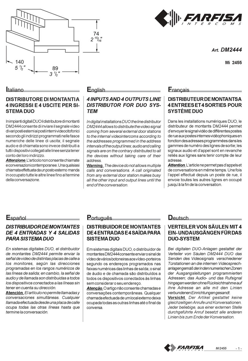
FARFISA INTERCOMS DM2444 User manual

FARFISA INTERCOMS

FARFISA INTERCOMS DM2444 User manual

Popular Intercom System manuals by other brands

Arlo HD Camera plus Audio Doorbell quick start guide

Arlo

Arlo HD Camera plus Audio Doorbell quick start guide

Vimar PIXEL UP 40415.S user manual

Vimar

Vimar PIXEL UP 40415.S user manual

Bticino CLASSE 100X installation manual

Bticino

Bticino CLASSE 100X installation manual

golmar Vista Plus Rock Series instruction manual

golmar

golmar Vista Plus Rock Series instruction manual

David Clark 9800 Series installation manual

David Clark

David Clark 9800 Series installation manual

Cyfral CC-4000 Operating, Installation and Programming Manual

Cyfral

Cyfral CC-4000 Operating, Installation and Programming Manual

Orisec CT-10 user guide

Orisec

Orisec CT-10 user guide

2N IP Vario installation manual

2N

2N IP Vario installation manual

Akuvox R20K Admin guide

Akuvox

Akuvox R20K Admin guide

Chamberlain WIRELESS PORTABLE INDOOR/OUTDOOR INTERCOM... user manual

Chamberlain

Chamberlain WIRELESS PORTABLE INDOOR/OUTDOOR INTERCOM... user manual

Commax CDV-43U user manual

Commax

Commax CDV-43U user manual

Avidsen YLVA 3+ manual

Avidsen

Avidsen YLVA 3+ manual

BASI TS810 Mounting and operating instructions

BASI

BASI TS810 Mounting and operating instructions

Tador TOPAZ user guide

Tador

Tador TOPAZ user guide

Commax CDV-43K user manual

Commax

Commax CDV-43K user manual

Axis A8004-VE installation guide

Axis

Axis A8004-VE installation guide

Anchor AnchorMAN owner's manual

Anchor

Anchor AnchorMAN owner's manual

Vimar ELVOX Pixel Up Series Installation and wiring manual

Vimar

Vimar ELVOX Pixel Up Series Installation and wiring manual

manuals.online logo
manuals.online logoBrands
  • About & Mission
  • Contact us
  • Privacy Policy
  • Terms and Conditions

Copyright 2025 Manuals.Online. All Rights Reserved.