manuals.online logo
Brands
  1. Home
  2. •
  3. Brands
  4. •
  5. Festo
  6. •
  7. Control Unit
  8. •
  9. Festo VZQA-C-M22C-6-GG-V2V4E-1 User manual

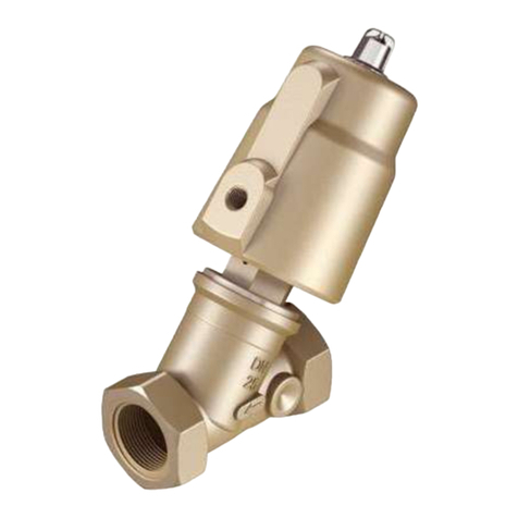
Festo VZQA-C-M22C-6-GG-V2V4E-1 User manual

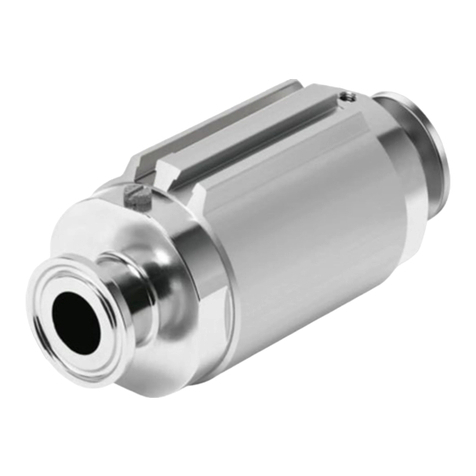
Pinch valve
VZQA-C-M22C-6-GG-V2V4E-1
Festo AG & Co. KG
Ruiter Straße 82
73734 Esslingen
Germany
+49 711 347-0
www.festo.com
Operating instructions
(Original instructions)
8075498
2017-08
[8075500]
Pinch valve VZQA-C-M22C-6-GG-V2V4E-1 English..........................
For all available product documentation èwww.festo.com/pk
1 Design
1
3
2
1
4
5
1Housing cover
2Housing
3Threaded connection for connect
ing media-carrying pipeline
4Blanking screw on exhaust port
5Operating medium port
Fig. 1
Inside the valve are compression springs, pistons and a diverter as well as a re
placeable seal cartridge with rods and a tubular shut-off element.
Product variants and type code
Characteristic Version Description
Type VZQA Pinch valve, pneumatically actuated
Product version CEasy to clean design (Clean Design)
Valve function M22C 2/2-way valve,
normally closed (NC)
Nominal diameter DN 66 mm
Process valve port 1 GG-female thread
Process valve port 2 GG-female thread
Housing material V2 Stainless steel
Housing cover material V4 Stainless steel
Material, shut-off element E EPDM
Pressure range of media 10 … 1 bar
Fig. 2
2 Safety
Intended use
Valves in the VZQA-C-M22C-... series are intended for controlling gaseous, liquid
and paste-like media with low to medium switching frequency.
– The product may only be used in its original status without unauthorised modi
fications.
– Only use the product if it is in an excellent technical status.
– Take into consideration the ambient conditions at the location of use.
– Observe the specifications on the rating plate.
Media
– Use only media in accordance with the specifications (èTechnical data).
– Use only media that the material used for the seal cartridge and cover are resist
ant to.
For evaluation of the resistance to media èwww.festo.com.
– Use only media that will not cause dangerous reactions if mixed.
Due to its design, the valve is not generally suitable for solids (granulates).
– Before using solids (granulates), the customer should determine suitability.
Piping system
Dependent on the medium and the operating conditions, pressure peaks that ex
ceed the permissible pressure range can develop in the system. The valve can
open accidentally and medium can exit.
– If necessary, plan for a pressure limitation valve in the media line to comply with
the limit values.
The separation between the media spaces is no longer guaranteed if wear causes
the seal cartridge (hose) to leak.
– Flow medium can exit at the exhaust port. Prevent possible hazards to persons
or material damage through suitable constructive measures.
– With ducted exhaust air, the flow medium can exit remotely from the valve. Pre
vent possible hazards to persons or material damage through suitable con
structive measures.
If the seal cartridge (shut-off element) leaks and the exhaust port is plugged (or in
the case of plugged ducted exhaust air or exhaust air in an equalising volume), the
flow medium can enter the operating medium.
– Use an appropriate non-return valve to protect the pilot circuit against ingress of
the flow medium.
– Check exhaust regularly.
Very high temperatures can damage the seal cartridge.
– Do not weld the piping in close proximity to the valve.
Return to Festo
Hazardous substances can endanger the health and safety of personnel and cause
damage to the environment. To prevent hazards, the product should only be re
turned upon explicit request by Festo.
– Consult your regional Festo contact.
– Complete the declaration of contamination and attach it to the outside of the
packaging.
– Comply with all of the legal requirements for the handling of hazardous sub
stances and the transport of dangerous goods.
3 Function
The pinch valve is a pneumatically actuated 2/2-way valve.
At rest, the valve is closed by spring force (normally
closed – NC).
Fig. 3
If the valve is pressurised with operating pressure, it moves the piston and the
diverter against the spring force. The rods thus untensioned are now freely mov
able to the outside and are placed on the outside by the blocking element. The
flow medium can now flow through the valve.
After the operating pressure is removed, the spring moves the diverter against the
rods and brings them back to the initial position. The valve closes.
4 Transport and storage
 When shipping used products: Comply with all legal requirements for handling
hazardous substances and transporting dangerous goods.
For return to Festo èChapter 2.
 Store the product in a cool (storage temperature 6…8 °C), dry, UV- and corro
sion-protected environment. Ensure storage times are short.
5 Installation
Note
Installation should only be conducted by qualified specialized personnel.
Do not reach into the opening of the valve.
Requirements
– The piping system is unpressurized, and no medium flows in it.
– The lines are clean.
– The lines ends are mounted.
– The system-provided safeguardings are installed (e.g. throttle valve or control
valve, non-return valve, pressure limitation valve).
Clean valve
 Remove all transport packaging. The material used in the packaging has been
specifically chosen for its recyclability (exception: oil-impregnated paper = re
sidual waste).
Residues of grease may be evident on the product due to the production process
used.
 Clean valve immediately before installation.
Connect medium lines
Note
To eliminate direct access to the valve opening during operation, connect a line
to both ports, even if the valve is located at the end of the piping.
 Screw the valve connections to the line.
– Tightening torque 10 Nm.
Connect the line of the operating medium
1. Mount the fitting to the operating medium connection.
– Max. permissible screw-in depth: 3 mm.
2. Connect the line of the operating medium.
3. Make sure that the blanking screw is mounted to the exhaust port.
With ducted exhaust air:
4. Remove the blanking screw at the exhaust port.
5. Connect the piping for the ducted exhaust air to the exhaust port.
– Max. permissible screw-in depth: 3 mm.
6 Commissioning
Note
Commissioning should only be conducted by qualified personnel.
Requirements
– The system-provided safeguardings are installed (e.g. throttle valve or control
valve, non-return valve, pressure limitation valve).
– The valve is fully mounted and connected.
Check operating conditions
Warning
Risk of injury from hot media under pressure!
Dependent on the medium and the operating conditions, pressure peaks that
exceed the permissible pressure range can develop in the system. The valve can
open accidentally and medium can exit.
 Do not exceed the maximum permissible medium pressure. In doing so, take
pressure peaks in the system into account.
 Check operating conditions and limit values (èTechnical data).
 Check connection points for tightness.
 Check compatibility of the devices in the system for maximum pressure (con
sider pressure peaks). If necessary, adjust the application parameters.
Placing valve in operation
1. Add medium.
2. Apply operating pressure to the valve.
èThe valve opens.
7 Operation
Warning
Risk of injury from hot media under pressure!
If the seal cartridge (shut-off element) leaks and the exhaust port is plugged (or
in the case of plugged ducted exhaust air or exhaust air in an equalising
volume), the flow medium can enter the operating medium.
 Use only media that will not cause dangerous reactions if mixed.
Warning
Risk of injury due to hot surface!
The valve can become hot at high media temperature.
 Do not touch the valve during operation or immediately afterward.
 Observe the operating conditions.
 Observe permissible limits.
 Comply with maintenance conditions (èMaintenance and care).
Recommendation: Switch valve several times per day.
After longer standstills:
 Actuate the valve several times and check for correct function.
8 Maintenance and care
Warning
Risk of injury from combustion and chemical burns.
The media in the piping system and the valve can be hot and under pressure.
Medium residues can be in the product and escape when open or dismantled.
 Allow the valve and piping to cool and depressurize them.
 Wear specified protective equipment.
Check and clean valve
 Check product regularly from the outside for leakage and function.
 Check blanking screw and ducted exhaust air for passage. Remove blockages.
 Clean product regularly.
Note
Plan for ducted exhaust air when cleaning the outside. To do this, replace the
blanking screw with a threaded insert or connector (max. permissible screw-in
depth: 3 mm).
Check and replace seal cartridge
Note
Seal cartridge may only be changed by qualified personnel following the mount
ing instructions (èMounting instructions for seal cartridge).
The seal cartridge is subjected to mechanical loads and ageing. A damaged or
worn seal cartridge results in leakage.
 Check and replace seals and seal cartridge regularly (intervals dependent on the
medium).
 Replace seal cartridge and seals if they are damaged. Use a seal cartridge with
the same specification.
 Replacement interval of the seal cartridge: max. ½ million switching cycles.
9 Disassembly
Warning
Risk of injury from combustion and chemical burns.
The media in the piping system and the valve can be hot and under pressure.
Medium residues can be in the product and escape when open or dismantled.
 Allow the valve and piping to cool and depressurize them.
 Wear specified protective equipment.
Note
Disassembly only by qualified specialized personnel.
Do not reach into the opening of the valve.
1. De-pressurise the piping and the operating medium line.
2. Allow the valve and pipeline to cool.
3. Empty the piping and valve completely.
– Make sure no one is located in front of the outlet opening.
– Catch discharging media in a suitable container.
4. Disconnect the operating medium line from the valve.
5. Disconnect the piping connections and remove the valve.
10 Disposal
 Observe the local specifications for environmentally friendly disposal.
 Dispose of the product in an environmentally friendly manner. When doing this,
also take residual media into account (potential recycling of hazardous waste).
11 Fault clearance
Malfunction Possible cause Remedy
Valve does not open or
opens too slowly
Valve clogged  Clean valve or replace seal cartridge
Operating medium line
clogged
 Clean or replace operating medium
line
Gluing of the shut-off
element, because the
material of the shut-off
element is not suited for the
medium
 Replace product with a product
variant made of appropriate
materials
Seal cartridge defective  Replace seal cartridge
Valve opens
accidentally
Medium pressure too high  Reduce medium pressure
Seal cartridge defective  Replace seal cartridge
Valve does not close or
closes too slowly
Operating pressure is still
present
 Switch off the operating pressure
Seal cartridge defective  Replace seal cartridge
Leakage Seal cartridge defective  Replace seal cartridge
Fig. 4
12 Accessories
Accessories èwww.festo.com/catalogue.
13 Technical data
General VZQA-C-M22C-6-GG-V2V4E-1
Design Pinch valve, pneumatically actuated
Nominal size DN 6
Actuation type Pneumatic
Sealing principle Soft
Mounting position Any
Type of mounting In-line installation
Valve function 2/2-way, closed, monostable
Direction of flow Reversible
Reset method Mechanical spring
Type of pilot control Externally actuated
Switching time on [ms] 125
Flow rate Kv [m3/h] 0.7
Switching time off [ms] 125
Medium pressure [bar] 0…1
Nominal pressure of process valve PN 10
Burst pressure [bar] 16
Operating pressure [bar] 3.5 … 6.0
Operating medium Compressed air in accordance with
ISO8573-1:2010 [7:4:1]
Medium Compressed air in accordance with
ISO8573-1:2010 [-:-:1], water
Max. viscosity [mm²/s] 4000
Temperature of medium [°C] 15 …50
Ambient temperature [°C] –5…+60
Storage temperature [°C] 6…8
Product weight èwww.festo.com/catalogue
Process valve connection G¼
Operating medium port 12 M3
Housing material High-alloy stainless steel (1.4301)
Housing cover material High-alloy stainless steel (1.4435)
Material of seals FPM
Material, shut-off element EPDM
Fig. 5
Tightening torques VZQA-C-M22C-6-GG-V2V4E-1
Housing cover, customer interface,
connection type G/T
[Nm] 10 ± 10 %
Housing cover with piping èMounting instructions for seal cartridge
Housing cover with housing
Fig. 6

Other Festo Control Unit manuals

Festo ZSB-1/8 User manual

Festo

Festo ZSB-1/8 User manual

Festo CAMC-G-S3 Instruction Manual

Festo

Festo CAMC-G-S3 Instruction Manual

Festo FSSC-12 User manual

Festo

Festo FSSC-12 User manual

Festo VIFB13 Series User manual

Festo

Festo VIFB13 Series User manual

Festo CP-FB13-E Parts list manual

Festo

Festo CP-FB13-E Parts list manual

Festo CP-FB13-E Owner's manual

Festo

Festo CP-FB13-E Owner's manual

Festo CAMC-G-S1 User manual

Festo

Festo CAMC-G-S1 User manual

Festo CPE PRS Series User manual

Festo

Festo CPE PRS Series User manual

Festo VPCF-6-L-8 Series User manual

Festo

Festo VPCF-6-L-8 Series User manual

Festo CPX Series User manual

Festo

Festo CPX Series User manual

Festo CPX-4AE-4AA-H Operating and installation instructions

Festo

Festo CPX-4AE-4AA-H Operating and installation instructions

Festo CTEU-CP Operating and installation instructions

Festo

Festo CTEU-CP Operating and installation instructions

Festo CDVI Series Parts list manual

Festo

Festo CDVI Series Parts list manual

Festo ZSB-1/8-B User manual

Festo

Festo ZSB-1/8-B User manual

Festo VABF-S4-1-V2B1 series User manual

Festo

Festo VABF-S4-1-V2B1 series User manual

Festo CP-FB13-E Parts list manual

Festo

Festo CP-FB13-E Parts list manual

Festo CPE-10-PRS series User manual

Festo

Festo CPE-10-PRS series User manual

Festo CTEU-EP User manual

Festo

Festo CTEU-EP User manual

Festo VABF-P5-Series-A3 User manual

Festo

Festo VABF-P5-Series-A3 User manual

Festo CPX-P-8DE-N Series Operating and installation instructions

Festo

Festo CPX-P-8DE-N Series Operating and installation instructions

Festo CPX-FB40 Operating and installation instructions

Festo

Festo CPX-FB40 Operating and installation instructions

Festo CPX-E User manual

Festo

Festo CPX-E User manual

Festo DLP-VSE-x-ASI eries User manual

Festo

Festo DLP-VSE-x-ASI eries User manual

Festo VZWP-L-M22C-P4 Series User manual

Festo

Festo VZWP-L-M22C-P4 Series User manual

Popular Control Unit manuals by other brands

Rockwell Automation ControlLogix 1756 Series Selection guide

Rockwell Automation

Rockwell Automation ControlLogix 1756 Series Selection guide

Allen-Bradley MicroLogix 1200 installation instructions

Allen-Bradley

Allen-Bradley MicroLogix 1200 installation instructions

SMC Networks VZ400 Series quick start guide

SMC Networks

SMC Networks VZ400 Series quick start guide

LEGRAND IC5010 Instruction/installation sheet

LEGRAND

LEGRAND IC5010 Instruction/installation sheet

Viola Systems ESERV-10 user manual

Viola Systems

Viola Systems ESERV-10 user manual

National Instruments FieldPoint FP-1001 user manual

National Instruments

National Instruments FieldPoint FP-1001 user manual

swissflex uni_75RF operating instructions

swissflex

swissflex uni_75RF operating instructions

Aventics TC08 Operation/Assembly/Exchange/Expansion

Aventics

Aventics TC08 Operation/Assembly/Exchange/Expansion

Beckhoff EP5 Series Documentation

Beckhoff

Beckhoff EP5 Series Documentation

Tanda TX7230 Installation and operation manual

Tanda

Tanda TX7230 Installation and operation manual

Metso Full Bore Fire-Tite 9REL Series Installation maintenance and operating instructions

Metso

Metso Full Bore Fire-Tite 9REL Series Installation maintenance and operating instructions

Dynamic DX-REMG91 installation manual

Dynamic

Dynamic DX-REMG91 installation manual

Growatt ShineWiFi-X Configuration guide

Growatt

Growatt ShineWiFi-X Configuration guide

Samsung SPC-6000 user manual

Samsung

Samsung SPC-6000 user manual

Vimar Elvox 6153/682 Installer's guide

Vimar

Vimar Elvox 6153/682 Installer's guide

IRT CP Installation, operation & maintenance manual

IRT

IRT CP Installation, operation & maintenance manual

Mirabelle MIRRI9009CP manual

Mirabelle

Mirabelle MIRRI9009CP manual

Globalstar ST150M user manual

Globalstar

Globalstar ST150M user manual

manuals.online logo
manuals.online logoBrands
  • About & Mission
  • Contact us
  • Privacy Policy
  • Terms and Conditions

Copyright 2025 Manuals.Online. All Rights Reserved.