Festo ADN-KP Series Setup guide

Repair
instructions (en)
Cylinder with piston rod
Compact cylinder with standard hole
pattern
ADN-…-KP with clamping unit and
ADN-…-EL with end-position locking
7ADN-KP_ADN-ELa_en

2 / 36 Festo 7ADN-KP_ADN-ELa_en
Imprint
Version:
7ADN-KP_ADN-ELa_en (06.2013)
Copyright:
©Festo AG & Co. KG
P.O. Box
73726 Esslingen
Germany
Editorial team:
SC-S
Tel.:
+49 (0) 711 / 347-0
Fax:
+49 (0) 711 / 347-2144
E-mail:
Internet:
http://www.festo.com
Reproduction, distribution or sale of
this document or communication of
its contents to others without express
authorisation is prohibited. Offenders
will be liable for damages. All rights
reserved in the event that a patent,
utility model or design patent is
registered.
All product designations and brand
names used are the property of the
owners and not explicitly identied
as such.
All technical data are subject to
change according to technical
updates.

3 / 36Festo 7ADN-KP_ADN-ELa_en
Preface
These repair instructions are valid for the cylinders with piston rod listed on the
title page to the exclusion of any liability claims.
Deviations compared to the descriptions in these repair instructions may arise
depending on the design and/or modication status of the cylinder with piston
rod. The user must check this prior to carrying out the repair and take the
deviations into consideration if necessary.
These repair instructions have been prepared with care.
Festo AG & Co. KG does not, however, accept liability for any errors in these
repair instructions or their consequences. Likewise no liability is accepted for
direct or consequential damage resulting from improper use of the products.
More detailed information on this can be found in chapter 10 "Liability".
The relevant regulations on occupational safety, safety engineering and
interference suppression as well as the stipulations contained in these repair
instructions must be observed when working on the products.

4 / 36 Festo 7ADN-KP_ADN-ELa_en
Table of contents
1 Important information 6
1.1 About these repair instructions 6
1.2 Pictograms used in these repair instructions 6
1.3 General safety instructions 7
2 General product description 7
2.1 Functional description 7
2.2 Functional description of ADN-…-KP 7
2.3 Functional description of ADN-…-EL 8
2.4 Type codes (ascertaining the features of a cylinder) 9
2.5 Orientation designations and bearing cap variants 10
3 Component overview 11
3.1 Compact cylinders ADN-KP, standard hole pattern, with clamping unit KP 11
3.2 Compact cylinders ADN-EL, standard hole pattern, with end-position locking 13
3.2.1 ADN-…-…-ELB-… 13
3.2.2 ADN-…-…-ELH-… 15
3.2.3 ADN-…-…-ELV-… 17
4 Repair steps 19
4.1 Preparation 19
4.2 Visual inspection 19
4.3 Cylinders ADN-…-KP 19
4.4 Cylinders ADN-…-EL 19
5 Repairing cylinder ADN-…-KP 20
5.1 Structure of the covers 20
5.1.1 Structure of the bearing cap 20
5.1.2 Structure of cover with clamping unit KP 20
5.2 Removing the covers 20
5.3 Removing the piston rod from clamping unit KP 21
5.4 Replacing the piston components 22
5.5 Inserting the piston rod into the cylinder barrel 22
5.6 Repairing and attaching the covers 23
6 Repairing cylinder ADN-…- EL 27
6.1 Structure of the bearing cap 27
6.1.1 Structure of the bearing cap without end-position locking 27
6.1.2 Structure of the bearing cap with end-position locking 27
6.2 Removing the covers 27
6.3 Replacing the piston components 28
6.4 Inserting the piston rod into the cylinder barrel 29
6.5 Repairing and attaching the bearing, intermediate and end caps 30
6.6 Reestablishing the functionality of the locking cylinder 32
6.6.1 Assembly of the locking cylinder following disassembly 32
6.6.2 Releasing the end-position locking 33

5 / 36Festo 7ADN-KP_ADN-ELa_en
7 Cleaning and greasing 34
7.1 Cleaning 34
7.2 Greasing 34
7.2.1 Extremelythingreaselm 34
7.2.2 Thingreaselm 34
7.2.3 Greasereservoir 34
8 Maintenance and care 34
9 Tools 35
9.1 Standard tools 35
9.2 Special tools 35
10 Liability 35

6 / 36 Festo 7ADN-KP_ADN-ELa_en
1 Important information
1.1 About these repair instructions
This document contains important
information about the professional
repair of the cylinder with piston rod
of the type ADN-…-KP and ADN-…-EL.
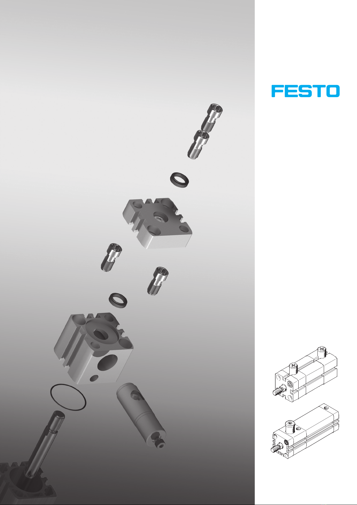
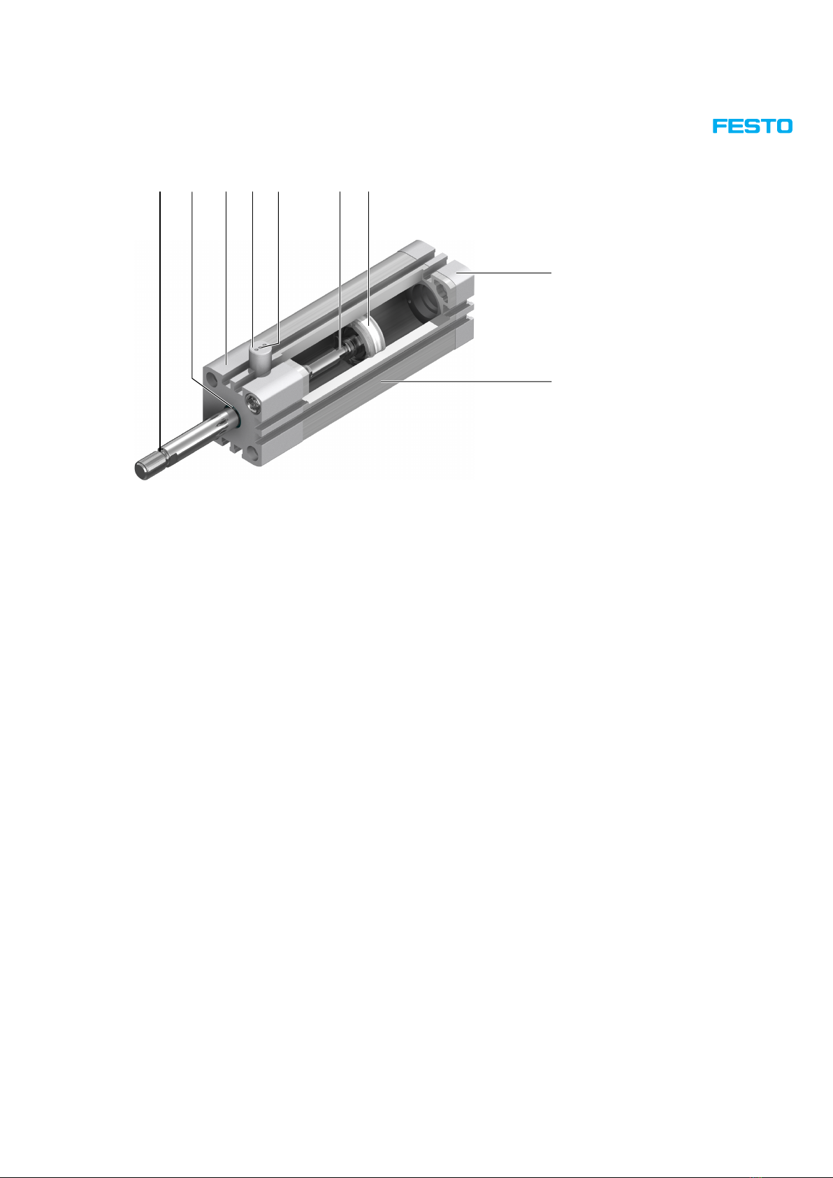
The cylinder with piston rod ADN-…-KP
and ADN-…-EL is fully repairable in the
event of damage due to normal wear.
The entire cylinder must be replaced
in the event of damage to the cylinder
barrel.
Before carrying out a repair, the
relevant chapter in these instructions
must be read in full and followed
consistently.
For reasons of clarity, these repair
instructions do not contain complete
detailed information. The following
documents should therefore also be
available when repairing the cylinder
with piston rod:
• Operating instructions for the
respective cylinder with piston
rod
Contains information about
the operating elements and
connections of the cylinder with
piston rod as well as the function,
structure, application, installation,
commissioning, maintenance and
care, etc. can be found on the
Festo website (www.Festo.com).
• Spare parts documentation
Contains an overview of the spare
and wearing parts as well as
information on their installation.
Can be found in the online spare
parts catalogue on the Festo
website (spareparts.festo.com).
• Assembly aids
Contains an overview of available
assembly aids such as lubricating
greases, locking agents,
maintenance tools, etc. (aids
for assembly and maintenance).
Can be found in the online spare
parts catalogue on the Festo
website (www.Festo.com).
1.2 Pictograms used in these repair instructions
Warning
This sign indicates a dangerous situation for persons and/or the product. Failure to observe this warning can result
in injury to persons and/or damage to the device.
Note
This sign provides important tips and information that can make your work easier.
Environment
This sign provides information on the steps required for environmentally-friendly use of materials and equipment,
as well as the guidelines and regulations that may need to be observed.
Accessories
This sign contains information on accessories and attachments relevant to the context.
Documents
This sign contains references to other chapters or documents containing additional information.

7 / 36Festo 7ADN-KP_ADN-ELa_en
1.3 General safety instructions
Warning
The cylinder with piston rod must only be repaired by authorised and trained persons in accordance with the
specications in the technical documentation and using original spare parts.
Installation and repair by unauthorised and untrained persons, repairs using non-original spare parts or without
the technical documentation required for installation and/or repair are dangerous and therefore not permitted.
Repairs must only be carried out in conjunction with these repair instructions and the device-specic operating
instructions.
Note
Instead of carrying out the repair yourself, your local Festo sales ofce offers the option of having the repair carried
out by Festo.
Environment
Components and equipment replaced as part of a repair must be disposed of in accordance with the locally valid
environmental protection regulations.
2 General product description
2.1 Functional description
The piston moves in the cylinder barrel when the cylinder chamber is pressurised. The piston rod transmits the movement
to the outside. The advanced piston rod is retracted again when the other cylinder chamber is pressurised.
2.2 Functional description of ADN-…-KP
aA
aJ
9
1 3 4 5 8762 1Piston rod
2Piston rod seal
3Bearing cap
4Cover
5Clamping unit KP
6Compressed air connection
clamping unit KP
7Front compressed air connection
8Piston (one-piece)
(only ADN-20 / 25 / 32-…-KP)
9Rear compressed air connection
aJ End cap
aA Cylinder barrel

8 / 36 Festo 7ADN-KP_ADN-ELa_en
2.3 Functional description of ADN-…-EL
9
8
1 3 4 7652 1Piston rod
2Piston rod seal
3Bearing cap
4End-position locking at front
5Compressed air connection end-
position locking
6Slot in the piston rod for the end-
position locking.
7Piston (one-piece)
(only ADN-20 / 25 / 32-…-EL)
8End cap
9Cylinder barrel

9 / 36Festo 7ADN-KP_ADN-ELa_en
2.4 Type codes (ascertaining the features of a cylinder)
The precise features of the current cylinder with piston rod can be ascertained with the help of the rating plate on the
cylinder. The type designation is located directly beneath the Festo logo and describes the cylinder's features separated
by a hyphen (-).
Example:
ADN-32-50-KP-A-P-A
548208 C608
pmax. 10bar
1
42
3
1Type designation
2Serial number
3Technical information
4Part number
The type designation on this rating plate provides the following information:
ADN Compact cylinder, double-acting, standard hole pattern, with clamping unit KP
32 Piston diameter 32 mm
50 Stroke 50 mm
KP Clamping unit attached
AMale thread
PElastic cushioning rings/pads at both ends
ASensing option (magnetic piston)
Note
A list and description of all possible equipment features of the cylinder with piston rod can be found in the data sheet.
It is available on the Festo website (www.Festo.com).

10 / 36 Festo 7ADN-KP_ADN-ELa_en
2.5 Orientation designations and bearing cap variants
This diagram provides an overview of the orientation designations for the cylinder with piston rod.
Orientation:
Festo = product identi cation (rating
plate) as reference point
O = top
U = underneath
R = right
L = left
V = front
H = rear

11 / 36Festo 7ADN-KP_ADN-ELa_en
3 Component overview
3.1 Compact cylinders ADN-KP, standard hole pattern, with clamping unit KP
This diagram is intended only to provide an overview of the individual components. To order spare and wearing parts, please use the
online spare parts catalogue on the Festo website (spareparts.festo.com).
2
1
21
21
1
4
3
5
5
6
4
8
4
10
9
11
12
2
2
2
4
8
8
21
21
1
1
13
14
15
13
16
18
17
19
20
8
20
7
7
6
3

12 / 36 Festo 7ADN-KP_ADN-ELa_en
Item Designation Note
1 Flange screw Only ADN-20 – 63-…-KP, use screw locking agent
2 Piston rod seal
3 Bearing cap
4 Bearing
5 Flange screw Use screw locking agent
6 Cover
7 Clamping cartridge
8 O-ring
9 Cylinder barrel
10 Piston rod, male thread Only ADN-…-…-KP-A-…
11 Piston rod, female thread Only ADN-…-…-KP-I-…
12 Piston Only ADN-20 – 32-…-KP
13 Seal piston
14 O-ring
15 Magnet
16 Guiding band
17 Nut Only ADN-20 / 25-…-KP, use screw locking agent
18 Washer Only ADN-32 – 100-…-KP
19 Hex nut Only ADN-32 – 100-…-KP, use screw locking agent
20 End cap
21 Socket head screw Only ADN-80 / 100-…-KP, use screw locking agent

13 / 36Festo 7ADN-KP_ADN-ELa_en
3.2 Compact cylinders ADN-EL, standard hole pattern, with end-position locking
3.2.1 ADN-…-…-ELB-…
This diagram is intended only to provide an overview of the individual components. To order spare and wearing parts, please use the
online spare parts catalogue on the Festo website (spareparts.festo.com).
2
1
1
3
2
3
3
4
7
4
4
11
5
11
11
12
13
14
9
10
2
2
21
21
5
6
5
6
5
6
21
21
2
2
2
2
15
20
16
17
15
18
19
5
9
10
20
9
10
20
9
8
10
9
10
9
10
8

14 / 36 Festo 7ADN-KP_ADN-ELa_en
Item Designation Note
1 Hex nut Not ADN-20/25-…-ELB-A-…, not ADN-…-…-ELB-I-…
2 Flange screw Only ADN-20 – 63-…-ELB, use screw locking agent
3 Piston rod seal
4 Bearing cap
5 O-ring
6 Bearing
7 Intermediate cap Only ADN-20 / 25-…-ELB
8 Spacer ring Only ADN-20 / 25-…-ELB
9 Locking cylinder Use screw locking agent
10 Socket head screw
11 Cylinder barrel
12 Piston rod, male thread Only ADN-…-…-ELB-A-…
13 Piston rod, female thread Only ADN-…-…-ELB-I-…
14 Piston Only ADN-20 – 32-…-ELB
15 Seal piston
16 O-ring
17 Magnet
18 Guiding band
19 Threaded coupling Use screw locking agent
20 End cap
21 Socket head screw Only ADN-80 / 100-…-ELB, use screw locking agent

15 / 36Festo 7ADN-KP_ADN-ELa_en
3.2.2 ADN-…-…-ELH-…
This diagram is intended only to provide an overview of the individual components. To order spare and wearing parts, please use the
online spare parts catalogue on the Festo website (spareparts.festo.com).
2
1
1
3
2
3
3
4
4
4
7
7
7
8
9
10
19
17
18
2
2
20
20
5
6
20
20
2
2
2
2
11
16
12
13
11
14
15
5
17
18
16
17
18
16

16 / 36 Festo 7ADN-KP_ADN-ELa_en
Item Designation Note
1 Hex nut Only ADN-20/25-…-ELH-A-…, not ADN-…-…-ELH-I-…
2 Flange screw Only ADN-20 – 63-…-ELH; use screw locking agent
3 Piston rod seal
4 Bearing cap
5 O-ring
6 Bearing
7 Cylinder barrel
8 Piston rod, male thread Only ADN-…-…-ELH-A-…
9 Piston rod, female thread Only ADN-…-…-ELH-I-…
10 Piston Only ADN-20 – 32-…-ELH
11 Seal piston
12 O-ring
13 Magnet
14 Guiding band
15 Threaded coupling Use screw locking agent
16 End cap
17 Locking cylinder Use screw locking agent
18 Socket head screw
19 Spacer ring Only ADN-20 / 25-…-ELH
20 Socket head screw Only ADN-80 / 100-…-ELH, use screw locking agent

17 / 36Festo 7ADN-KP_ADN-ELa_en
3.2.3 ADN-…-…-ELV-…
This diagram is intended only to provide an overview of the individual components. To order spare and wearing parts, please use the
online spare parts catalogue on the Festo website (spareparts.festo.com).
2
1
1
3
2
3
3
4
7
4
4
11
5
11
11
12
13
14
2
2
23
23
5
6
5
6
5
5
6
23
23
2
2
15
16
17
15
18
20
19
21
22
5
22
9
8
10
9
10
9
10

18 / 36 Festo 7ADN-KP_ADN-ELa_en
Item Designation Note
1 Hex nut Not ADN-20/25-…-ELV-A-…, not ADN-…-…-ELV-I-…
2 Flange screw Only ADN-20 – 63-…-ELV, use screw locking agent
3 Piston rod seal
4 Bearing cap
5 O-ring
6 Bearing
7 Intermediate cap Only ADN-20 / 25-…-ELV
8 Spacer ring Only ADN-20 / 25-…-ELV
9 Locking cylinder Use screw locking agent
10 Socket head screw
11 Cylinder barrel
12 Piston rod, male thread Only ADN-…-…-ELV-A-…
13 Piston rod, female thread Only ADN-…-…-ELV-I-…
14 Piston Only ADN-20 – 32-…-ELV
15 Seal piston
16 O-ring
17 Magnet
18 Guiding band
19 Nut Use screw locking agent
20 Washer Only ADN-20 / 25-…-ELV
21 Hex nut Only ADN-20 / 25-…-ELV, use screw locking agent
22 End cap
23 Socket head screw Only ADN-80 / 100-…-ELV, use screw locking agent

19 / 36Festo 7ADN-KP_ADN-ELa_en
4 Repair steps
4.1 Preparation
• Before starting the repair, remove any attachments (clamping device, end-position locking, etc.) in accordance with
the accompanying operating instructions.
• Keep your working environment tidy.
• Only use the spare parts and assembly aids (grease, locking agent, etc.) provided in the set of wearing parts.
Warning
Make sure that the bearing cap cannot suddenly come ying off.
• Remove the non-return valves and tubing connection from the cylinder and depressurise the cylinder completely
so that any pressure present is not suddenly released when the cylinder is opened.
To prevent damage to sealing rims or guide surfaces, do not use pointed or sharp-edged assembly aids.
4.2 Visual inspection
Check the cylinder for visible damage that might impair its function (e.g. warping of the piston rod) as well as deposits
and scoring. The entire cylinder must be replaced if the cylinder barrel is showing signs of signicant damage.
4.3 Cylinders ADN-…-KP
The description in this chapter can be used to repair cylinders of the type ADN-…-KP with the following features:
Code Description Code Description
KP Clamping unit KP attached K2 Piston rod with extended male thread
A Male thread K5 Piston rod with special thread
I Female thread K8 Extended piston rod
P Elastic cushioning rings/pads at both ends Tl Captive rating plate
A External position sensing
The repair steps can be found in chapter 5 "Repairing cylinder ADN-…-KP".
4.4 Cylinders ADN-…-EL
The description in this chapter can be used to repair cylinders of the type ADN-…-EL with the following features:
Code Description Code Description
ELB End-position locking at both ends A External position sensing
ELV End-position lock at front K2 Piston rod with extended male thread
ELH End-position locking, rear K5 Piston rod with special thread
A Male thread K8 Extended piston rod
I Female thread Tl Captive rating plate
P Elastic cushioning rings/pads at both ends
The repair steps can be found in chapter 6 "Repairing cylinder ADN-…- EL".

20 / 36 Festo 7ADN-KP_ADN-ELa_en
5 Repairing cylinder ADN-…-KP
5.1 Structure of the covers
5.1.1 Structure of the bearing cap
1
2
3
1Bearing
2Bearing cap
3Piston rod seal
5.1.2 Structure of cover with clamping unit KP
1
4
3
2
5
1O-ring
2Bearing
3Clamping unit KP cover
4Piston rod seal
5Location hole for clamping unit KP
5.2 Removing the covers
• ADN-20 to 63-…-KP
– Loosen the ange screws in the bearing cap and and end cap and
remove them.
– Pull the bearing cap away from the piston rod.
– Remove the end cap from the cylinder barrel.
– Loosen the ange screws in the cover with clamping unit KP and remove
them.
– Pull the cylinder barrel from the piston rod.
– Remove any residue of the screw locking agent from the threads of the
screws.
This manual suits for next models
4
Table of contents
Other Festo Industrial Equipment manuals

Festo
Festo CPX-FB6 User manual

Festo
Festo ELGC-BS User manual

Festo
Festo DGEA Series User manual

Festo
Festo EGC-TB-KF User manual

Festo
Festo EGC Series User manual

Festo
Festo SLTE Series User manual

Festo
Festo CPX-AB-2-M12-RK-IB User manual

Festo
Festo YXCA User manual

Festo
Festo CPE PRS Series User manual

Festo
Festo VABM-B10-30EEE User manual

Festo
Festo YXML User manual

Festo
Festo MPS 8034567 User manual

Festo
Festo MS6-SP User manual

Festo
Festo HGRT Series User manual

Festo
Festo UOS-1-LF User manual

Festo
Festo DSNU-8 User manual

Festo
Festo 696688 User manual

Festo
Festo HSP Series Reference guide

Festo
Festo CRDSNU Series Setup guide

Festo
Festo DNCKE S Series User manual