– PROFINET IO
The interface [X10] of the controller is not supported. The controller cannot be
used as a switch.
TIPP!
The Ethernet interface is used to configure and parameterise the system through
a PC/tablet connected to the network. After the mechanical and electrical installa-
tion, the servo press kit can be commissioned with a web browser. Control and
process data can be exchanged with a higher-order controller through this inter-
face during the run-time of the system.
A requirement for this is integration of the CECC-X-M1-YJKP in the local network.
Minimum requirements for a PC/tablet
– Web browser with Java Script and support of HTML5 Canvas, e.g. Firefox,
Chrome, Internet Explorer ³ Version9
– Screen resolution 1024 x 768 pixels
Access is through entry in the address line:
http://<<IP address>>:8080/servo_press-kit.htm
Example: http://192.168.4.2:8080/servo_press_kit.htm
NOTICE!
Unauthorised access to the device can cause damage or malfunctions.
When connecting the device to a network, protect the network from unauthorised
access.
Measures to protect the network include:
• Firewall
• Intrusion prevention system (IPS)
• Network segmentation
• Virtual LAN (VLAN)
• Virtual private network (VPN)
• Security at physical access level (port security)
Further informationèDirectives and standards for security in information tech-
nology, e.g.IEC62443, ISO/IEC27001.
USB interface [X9]
The USB interface is compatible with the USB 3.0 and USB 2.0 standards. The
interface is suitable for USB flash drives with plug typeA.
Supported function: storage of results of press processes.
Digital inputs [X17]
The digital inputs, configured in 3-wire connection technology, are not galvanic-
ally separated. The ground potential for all inputs relates to GND of the power
supply [X1].
For connecting sensors with 3-wire connection technology: Use 3 adjacent termin-
als each.
NOTICE!
Material damage or loss of function due to incorrect I/O circuitry.
• All digital inputs/outputs are designed as PNP. Use only corresponding cir-
cuitry.
Terminal Connection Usage
X17.0.1 24V DC Power supply for sensor at
input 9
X17.0.2 Input DI9 Program selection 1)2)
X17.0.3 GND logic Power supply for sensor at
input 9
X17.1.1 24V DC Power supply for sensor at
input 10
X17.1.2 Input DI10 Program selection 1)2)
X17.1.3 GND logic Power supply for sensor at
input 10
X17.2.1 24V DC Power supply for sensor at
input 11
X17.2.2 Input DI11 Program selection 1)2)
X17.2.3 GND logic Power supply for sensor at
input 11
X17.3.1 24V DC Power supply for sensor at
input 12
X17.3.2 Input DI12 Program selection 1)2)
X17.3.3 GND logic Power supply for sensor at
input 12
X17.4.1 24V DC Power supply for safety
acknowledgement
X17.4.2 Servo press activation Release of motor controller out-
put stage via CECC-X controller
X17.4.3 GND logic Power supply for safety
acknowledgement
Terminal Connection Usage
X17.5.1…X17.5.3 reserved –
X17.6.1…X17.6.3 reserved –
X17.7.1…X17.7.3 reserved –
1) If all inputs are at 0, homing is carried out.
2) Only active if selected in system control.
Tab. 8
CANopen interface [X18]
TIPP!
The connecting cable between the controller CECC-X-M1-YJKP and the motor con-
troller CMMP-AS is not within the scope of delivery. The connecting cable is also
not offered as an accessory, since the cable length in the control cabinet can vary
considerably due to the arrangement of the individual components.
The connection is established via a cable provided by the customer.
• CANopen-Connect interface [X18] to motor controller CMMP-AS [X4].
CECC-X-M1-YJKP [X18] CMMP-AS [X4]
Plug NECC-L2G4-C1, 4-pin, socket D-sub plug connector, 9-pin, pin
Tab. 9
Terminal Connection Usage
X18.1 CAN_H 1) CAN bus signal (dominant high)
X18.2 CAN_L 1) CAN bus signal (dominant low)
X18.3 CAN_GND CAN Ground
X18.4 CAN_SHLD Connection to functional earth
1) No terminating resistor necessary; ports are connected internally via a resistor.
Tab. 10
Analogue input [X19]
The analogue inputs, configured in 3-wire connection technology, are not galvan-
ically separated. The ground potential of the input X19.0 relates to GND of the
power supply [X1]. An incoming signal is digitised with a 14bit resolution.
Terminal Connection Usage
X19.0.1 24V DC Power supply for force sensor
X19.0.2 Input 4…20mA Evaluation of the sensor signal
through servo press software
X19.0.3 reserved –
X19.1.1…X19.1.3 reserved –
X19.2.1…X19.2.3 reserved –
X19.3.1…X19.3.3 reserved –
Tab. 11
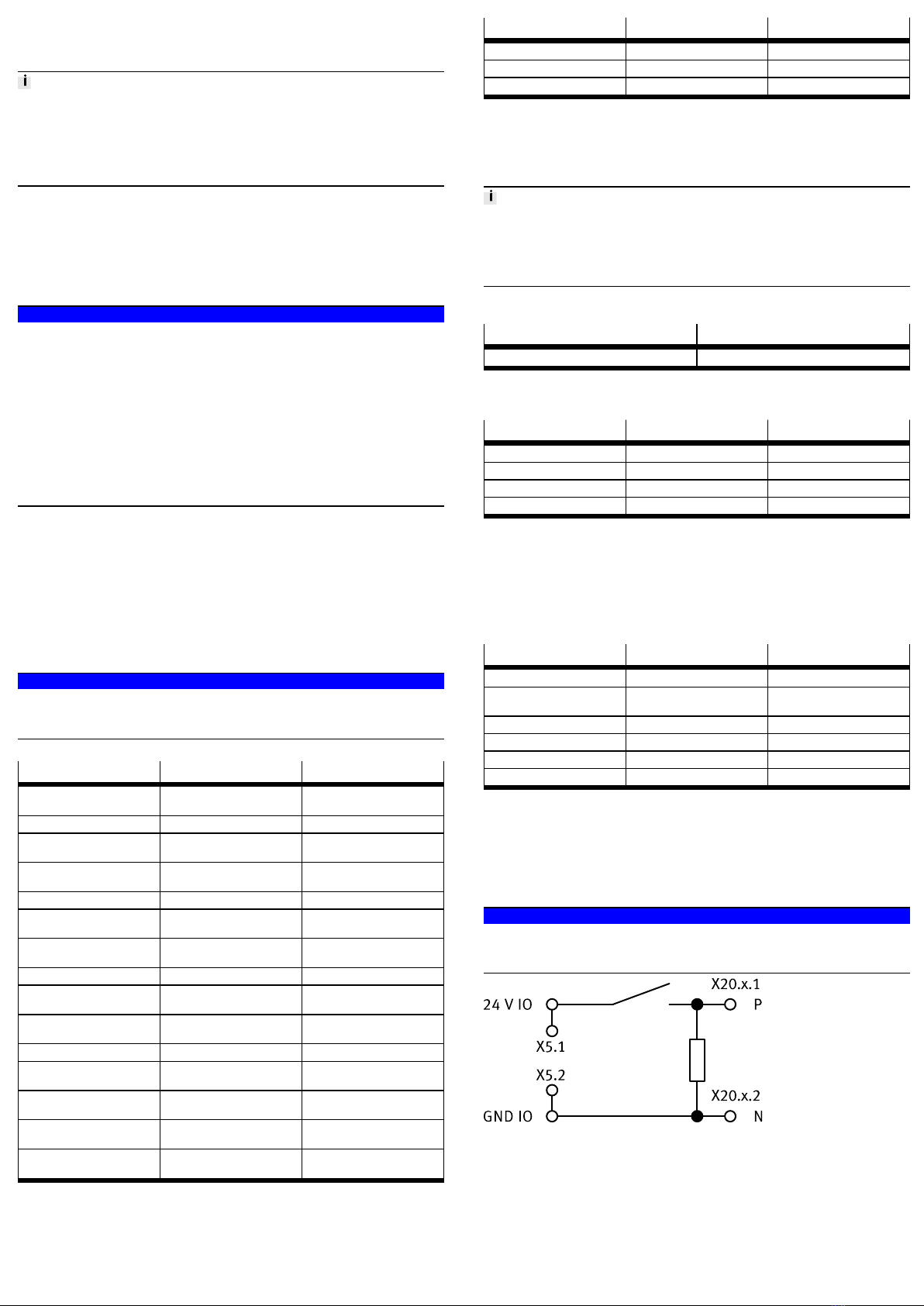
Digital outputs [X20]
The digital outputs, configured in 2-wire connection technology, are galvanically
separated. The current load for each output is 0.5A.
The ground potential for all outputs relates to GND of the power supply [X5]. All
outputs are protected against short circuit and thermal overload.
NOTICE!
Material damage or loss of function due to incorrect I/O circuitry.
• All digital inputs/outputs are designed as PNP. Use only corresponding cir-
cuitry.
Fig. 9
Use 2 adjacent terminals when connecting a consumer.