manuals.online logo
Brands
  1. Home
  2. •
  3. Brands
  4. •
  5. Festo
  6. •
  7. Touch Terminal
  8. •
  9. Festo CPX-FB33 Reference guide

Festo CPX-FB33 Reference guide

Translation of the original instructions
© 2020 all rights reserved to Festo SE & Co. KG
PI PROFIBUS PROFINET® is a registered trademark of its respective trademark
holder in certain countries.
1 About this document
1.1 Applicable Documents
All available documents for the product èwww.festo.com/sp.
Document Contents
CPX system description (CPX-SYS-...) Detailed information on the CPX terminal
Brief instructions for bus node Essential information on the product
Operating instructions for bus node Detailed information on the product
Tab. 1 Applicable Documents
2 Safety
2.1 Safety Instructions
– Only use the product in original status without unauthorised modifications.
– Only use the product if it is in perfect technical condition.
– Observe labelling on the product.
– Store the product in a cool, dry, UV-protected and corrosion-protected envir-
onment. Ensure that storage times are kept to a minimum.
– Before working on the product, switch off the power supply and secure it
against being switched on again.
– This product can generate high frequency malfunctions, which may make it
necessary to implement interference suppression measures in residential
areas.
– Comply with the handling specifications for electrostatically sensitive devices.
2.2 Intended Use
The bus node is intended exclusively for operation as a station (IO Device) in the
industrial Ethernet system PROFINETIO.
The product may only be used in combination with the CPX Terminal in an indus-
trial environment.
3 Configuration
3.1 Product design
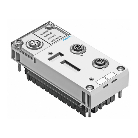
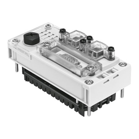
1LED Displays
2Memory card (only for
FB33/34/35)
3Network connection
4DIL Switch
5Service interface
6Product labelling
Fig. 1 Connection and display components
3.2 Product variants
The following software and hardware revisions are a prerequisite for using the
functions:
Bus bus node revision numberFunction
Software Hardware
Priority start-up (Fast Start-up) From Rev 12 From Rev 11
Identification & Maintenance
(I&M)
From Rev 14 From Rev 1
PROFIenergy From Rev 20 From Rev 1
Media Redundancy Protocol
(MRP)
From Rev 20 From Rev 1
Media Redundancy for Planned
Duplication (MRPD)
From Rev 50 From Rev 45
S2 system redundancy From Rev 50 From Rev 45
Isochronous real time (IRT) From Rev 21 From Rev 1
Tab. 2 Required revision numbers for using the functions
The revision numbers of the hardware and software for the bus node can be
checked with the control software, the Festo Maintenance Tool (FMT) or the
Festo Field Device Tool (FFT).
3.3 LED displays
LED Network status LEDs LED CPX-specific LEDs
NF Network Failure (red) PS Power System (green)
M/P Maintenance/PROFIenergy
(green or yellow)
PL Power Load (green)
TP1 Link/Traffic 1 (green) SF System Failure (red)
TP2 Link/Traffic 2 (green) M Modify (yellow)
Tab. 3 LEDs on the bus node
3.4 Control Elements
1Memory card
2DIL switch: operating mode
3DIL switch: diagnostics mode
Fig. 2 Control elements for PROFINET
8127864
CPX-(M)-FB33/34/35/43/44/45
Bus node
8127864
2020-04d
[8127866]
Brief instructions
Festo SE & Co. KG
Ruiter Straße 82
73734 Esslingen
Germany
+49 711 347-0
www.festo.com
DIL Switch
A bus node must be operated as a master in the CPX terminal. The "Remote I/O"
operating mode must be set on this bus node. The "Remote Controller " operating
mode must be set on all other bus nodes.
The 2DIL switch is used to set the operating mode :
DIL switch 2Description
1: OFF
2: OFF (factory set-
ting)
Remote I/O operating mode
All functions of the CPX terminal are controlled by the PROFINET
IO controller.
1: ON
2: OFF
Remote Controller operating mode
A CPX-CEC-xx takes over the I/O open-loop control. Requirement:
CPX Terminal with CEC.
Tab. 4 Setting the operating mode
The diagnostics mode or the data field size is set with the 3DIL switch depend-
ing on the operating mode:
DIL switch 3Description
Remote I/O Remote controller
1: OFF
2: OFF (factory set-
ting)
Diagnostics switched off. Data field size:
8bytes I/8bytes O
1: OFF
2: ON
Status bits
switched on
Data field size:
16bytes I/16bytes O
1: ON
2: OFF
I/O diagnostics interface
switched on
Data field size:
32bytes I/32bytes O
1: ON
2: ON
Reserved Reserved
Tab. 5 Setting the diagnostics mode
Reserved DIL switches are blocked for future functions and must not be used.
The setting of the DIL switches for operating mode and diagnostics mode must
match the settings in the open-loop control.
Memory card
The bus nodes CPX-(M)-FB43/44/45 do not support memory cards.
The memory card serves as a carrier for configuration data, suchas the fieldbus
device name. This makes it easy to replace a bus node. Detailed information on
use èBus node operating instructions.
NOTICE!
Malfunction or Damage to the Memory Card.
Inserting or removing the memory card while the power supply is switched on can
result in malfunctions of or damage to the memory card.
• Disconnect the power supply before you insert or remove the memory card.
The various bus node revisions are only compatible with the corresponding
memory card:
Memory card Bus bus node revision number
CPX-SK From Rev 07
CPX-SK-2 From Rev 12
CPX-SK-3 From Rev 30
Tab. 6 Compatibility of the memory cards depending on the bus node revision
3.5 Connecting Elements
Pin allocation of the network interface of the bus node CPX-FB33/43 (M12)
Bushing Pin Signal Explanation
1 TD+ Transmitted data (Transmit Data) +
2 RD+ Received data (Receive Data) +
3 TD– Transmitted data –
4 RD– Received data –
M12, D-coded
Housing Shield/FE Shield/functional earth
Tab. 7 Network interface of the bus node CPX-FB33/43
Pin allocation of the network interface of the CPX-M-FB34/44 bus node (RJ45)
Bushing Pin Signal Explanation
1 TD+ Transmitted data (Transmit Data) +
2 TD– Transmitted data –
3 RD+ Received data (Receive Data) +
4 n.c. Not connected
5 n.c. Not connected
6 RD– Received data –
7 n.c. Not connected
8 n.c. Not connected
RJ45, Push-pull
Housing Shield/FE Shield/functional earth
Tab. 8 Network interface of the bus node CPX-M-FB34/44
Pin allocation of the network interface of the CPX-M-FB35/45 bus node (SCRJ)
Bushing Pin Signal Explanation
1 TX Transmitted dataSCRJ, Push-pull
2 RX Received data
Tab. 9 Network interface of the bus node CPX-M-FB35/45
Overview of connections and plug
Bus node Connection technology Network connectors
CPX-FB33/43 2 x M12, D-coded, female, 4-pin, in
accordance with IEC61076-2
NECU-MS-D12G4-C2-ET
CPX-M-FB34/44 2 x RJ45, push-pull, Cu, AIDA, in
accordance with IEC60603,
IEC61076-3
FBD-RJ45-PP-GS
CPX-M-FB35/45 2 x SCRJ, push-pull, 650nm, AIDA, in
accordance with IEC61754-24
FBD-SCRJ-PP-GS
Tab. 10 Connection technology and network connectors
In the following table, the cable lengths were used in accordance with the spe-
cifications for PROFINET networks.
Network connectors Cable specification
NECU-MS-D12G4-C2-ET Ethernet cable, shielded, Cat5/5e, 6…8mm, 0.14…0.75mm2
(max. 100m PROFINET end-to-end link: 22AWG)
FBD-RJ45-PP-GS Ethernet cable, shielded, Cat5/Cat5e, 5…8mm,
0.13…0.36mm2 (≙approx.26…22AWG)
(max. 100m PROFINET end-to-end link: 22AWG)
FBD-SCRJ-PP-GS POF fibre-optic cable, 980/1000µm, 6.5…9.5mm
(max. 50m PROFINET end-to-end link; ≤12.5dB)
Tab. 11 Cable specification for network connectors
Service interface
An operator unit such asCPX-MMI-1 can be connected to the service interface.
Alternatively, the service interface can be connected to a PC via the USB adapter
NEFC-M12G5-0.3-U1G5 so that the "Festo Maintenance Tool" software (FMT) can
be used.
4 Assembly
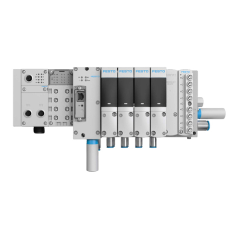
The bus node is mounted in an interlinking block of the CPX terminal.
1Screws
2CPX bus node
3Interlinking block
Fig. 3 Mounting the bus node in an interlinking block
– Before working on the product, switch off the power supply and secure it
against being switched on again.
– CPX-M-FB35/45 only permissible on metal linking.
Disassembly
1. Unscrew screws.
2. Carefully lift the bus node.
Assembly
1. Check seal and sealing surfaces and insert the bus node.
2. Screws must be placed so that the self-tapping threads are used. Tighten the
screws by hand cross-wise.
Tightening torque: 0.9…1.1Nm.
Use suitable screws for the interlinking block.
• Plastic interlinking block: thread-grooving self-tapping screws.
• Metal interlinking block: screws with metric thread.
5 Commissioning
NOTICE!
Malfunction due to incorrect switch-on sequence.
• First switch on the operating voltage supply of all network stations and then
the operating power supply of the open-loop control.
CPX- M-FB34: cyclical process data exchange can freeze in exceptional cases in
applications with increased electrostatic load.
This results in an entry in the diagnostic memory with error number FN150.
• Restart to ensure normal operation.
• Reduce electrostatic charges in the vicinity of the product or use a CPX Ter-
minal with metal interlinking (order code 51E).
6 Technical data
6.1 General
Characteristics CPX-FB33 CPX-M-FB34 CPX-M-FB35
Module code in the CPX Termin-
al
– Remote I/O
– Remote Controller
215
164
216
165
217
166
Module identification
– Remote I/O FB33-RIO PROFINET
remote I/O
FB34-RIO PROFINET
RJ45 remote I/O
FB35-RIO PROFINET
LWL remote I/O
– Remote Controller FB33-RC PROFINET
I/O bus node
FB34-RC PROFINET
RJ45 bus node
FB35-RC PROFINET
LWL bus node
Power Supply
Operating voltage/load voltage è CPX system description (CPX-SYS-…)
Intrinsic current consumption at
nominal operating voltage
24VDC,
from operating voltage supply
for electronics/sensors (UEL/SEN)
typ. 85mA
(internal electron-
ics)
typ. 85mA
(internal electron-
ics)
typ. 155mA
(internal electron-
ics)
Separation of the PROFINET
interfaces to UEL/SEN
electrically isolated
by transformer (up
to 1500V)
electrically isolated
by transformer (up
to 1500V)
electrically isolated
by fibre-optic cable
Mains buffering time 10ms 10ms 10ms
Tab. 12 Special characteristics of CPX-(M)-FB33/34/35
Characteristics CPX-FB43 CPX-M-FB44 CPX-M-FB45
Module code in the CPX Termin-
al
– Remote I/O
– Remote Controller
– Sub-module code
215
164
32
216
165
32
217
166
32
Module identification
– Remote I/O FB43-RIO PROFINET
remote I/O
FB44-RIO PROFINET
RJ45 remote I/O
FB45-RIO PROFINET
LWL remote I/O
– Remote Controller FB43-RC PROFINET
I/O bus node
FB44-RC PROFINET
RJ45 bus node
FB45-RC PROFINET
LWL bus node
Power Supply
Operating voltage/load voltage è CPX system description (CPX-SYS-…)
Intrinsic current consumption at
nominal operating voltage
24VDC,
from operating voltage supply
for electronics/sensors (UEL/SEN)
typ. 75mA
(internal electron-
ics)
typ. 75mA
(internal electron-
ics)
typ. 150mA
(internal electron-
ics)
Separation of the PROFINET
interfaces to UEL/SEN
electrically isolated
by transformer (up
to 1500V)
electrically isolated
by transformer (up
to 1500V)
electrically isolated
by fibre-optic cable
Mains buffering time 10ms 10ms 10ms
Accuracy of voltage measure-
ment
(operating voltage/load
voltage)
£ 5% £ 5% £ 5%
Tab. 13 Special characteristics of CPX-(M)-FB43/44/45
6.2 Network
Characteristics CPX-FB33/43 CPX-M-
FB34/44
CPX-M-
FB35/45
Transmission rate 100Mbit/s 100Mbit/s 100Mbit/s
Wavelength – – 650nm
(suitable for POF
fibre-optic cable)
Network connections 2 x M12 bushings,
D-coded, 4-pin
2 x RJ45 bushings,
push-pull, AIDA-con-
forming
2 x SCRJ bushings,
push-pull, AIDA-con-
forming
Crossover detection Auto MDI Auto MDI –
Max. addressing volume of out-
puts/inputs,
operating mode-independent
64 bytes I,
64 bytes O
64 bytes I,
64 bytes O
64 bytes I,
64 bytes O
Tab. 14 Special network characteristics CPX-(M)-FB33/34/35/43/44/45

Other manuals for CPX-FB33

6

This manual suits for next models

11

Other Festo Touch Terminal manuals

Festo CPV-VI Series User manual

Festo

Festo CPV-VI Series User manual

Festo CPX-CMXX Parts list manual

Festo

Festo CPX-CMXX Parts list manual

Festo CPX User guide

Festo

Festo CPX User guide

Festo CPV GE-ASI Series Parts list manual

Festo

Festo CPV GE-ASI Series Parts list manual

Festo MPA-L Series Operating and installation instructions

Festo

Festo MPA-L Series Operating and installation instructions

Festo VNIA-01-ZR Series Parts list manual

Festo

Festo VNIA-01-ZR Series Parts list manual

Festo CPX Series User manual

Festo

Festo CPX Series User manual

Festo CPX Series User manual

Festo

Festo CPX Series User manual

Festo CPX Series User manual

Festo

Festo CPX Series User manual

Festo CPV -GE-CO3-8 Series User manual

Festo

Festo CPV -GE-CO3-8 Series User manual

Festo CPV ASI-4E3A-Z Series Parts list manual

Festo

Festo CPV ASI-4E3A-Z Series Parts list manual

Festo IFB-03 Series User manual

Festo

Festo IFB-03 Series User manual

Festo CPV GE-ASI-8E8A-Z M8 Series Parts list manual

Festo

Festo CPV GE-ASI-8E8A-Z M8 Series Parts list manual

Festo CPX-FB32 User manual

Festo

Festo CPX-FB32 User manual

Festo CPV GE-ASI-8E8A-Z-M8-CE Series Parts list manual

Festo

Festo CPV GE-ASI-8E8A-Z-M8-CE Series Parts list manual

Festo MPAC-VI User manual

Festo

Festo MPAC-VI User manual

Festo CPX User manual

Festo

Festo CPX User manual

Festo CPV-SC Series User manual

Festo

Festo CPV-SC Series User manual

Festo CPX-FB13 User manual

Festo

Festo CPX-FB13 User manual

Festo IFB21-03 Series User manual

Festo

Festo IFB21-03 Series User manual

Festo CPX-FB13 User manual

Festo

Festo CPX-FB13 User manual

Festo VTSA-44-MP Series User manual

Festo

Festo VTSA-44-MP Series User manual

Festo VTUB-12-V Parts list manual

Festo

Festo VTUB-12-V Parts list manual

Festo CPX-M-FB20 User manual

Festo

Festo CPX-M-FB20 User manual

Popular Touch Terminal manuals by other brands

GalileoSky GLONASS user manual

GalileoSky

GalileoSky GLONASS user manual

hazeltine ESPRIT Reference manual

hazeltine

hazeltine ESPRIT Reference manual

POS-X ION TP5 user manual

POS-X

POS-X ION TP5 user manual

Symbol VRC 6940 Product reference guide

Symbol

Symbol VRC 6940 Product reference guide

TimeTec FingerTec Face ID 4 FMM user guide

TimeTec

TimeTec FingerTec Face ID 4 FMM user guide

ELTEX TAU-32M.IP Operation manual

ELTEX

ELTEX TAU-32M.IP Operation manual

RFL 9785 instruction manual

RFL

RFL 9785 instruction manual

ZETRON 2000 Series Configuration guide

ZETRON

ZETRON 2000 Series Configuration guide

CipherLab 256 Series quick start guide

CipherLab

CipherLab 256 Series quick start guide

FingerTec R3c user guide

FingerTec

FingerTec R3c user guide

Dover OPW PETROVEND PV300E quick start

Dover

Dover OPW PETROVEND PV300E quick start

Bosch Rexroth IndraControl VAK 41.2 manual

Bosch

Bosch Rexroth IndraControl VAK 41.2 manual

Bizerba iS10 operating instructions

Bizerba

Bizerba iS10 operating instructions

Radiall R280 Series manual

Radiall

Radiall R280 Series manual

Casio QT-6600 user manual

Casio

Casio QT-6600 user manual

AXIOMTEK SBC856A1 user manual

AXIOMTEK

AXIOMTEK SBC856A1 user manual

CDVI ievo IFACE manual

CDVI

CDVI ievo IFACE manual

Vololink VoloAccess VA100 Series Getting started guide

Vololink

Vololink VoloAccess VA100 Series Getting started guide

manuals.online logo
manuals.online logoBrands
  • About & Mission
  • Contact us
  • Privacy Policy
  • Terms and Conditions

Copyright 2025 Manuals.Online. All Rights Reserved.