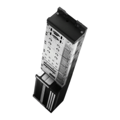
MPA-C
Festo – GDCV-MPAC-EN – 1407NH – English 3
Table of Contents – MPA-C
1 Safety and requirements for product use 8......................................
1.1 Safety 8..................................................................
1.1.1 General safety information 8..........................................
1.1.2 Intended use 8.....................................................
1.2 Requirements for product use 9...............................................
1.2.1 Technical prerequisites 9............................................
1.2.2 Qualification of specialized personnel 9.................................
1.2.3 Range of application and certifications 9................................
2Overview 10................................................................
2.1 Valve terminal MPA-C 10......................................................
2.1.1 Purpose 10........................................................
2.1.2 Performance characteristics 10........................................
2.1.3 Equipment levels 11.................................................
2.1.4 Size of the valves 11.................................................
2.2 Valve terminal design 12......................................................
2.3 Electrical connection 13.......................................................
2.3.1 Multi-pin plug connection 13..........................................
2.3.2 I-Port interface/IO-Link 13............................................
2.4 Description of components 14..................................................
2.4.1 Manifold sub-bases and electronics modules 14...........................
2.4.2 Valves. 15.........................................................
2.4.3 Cover of the manifold sub-base 16......................................
2.4.4 Pneumatic supply 18.................................................
2.4.5 Pilot air supply 18...................................................
2.4.6 Exhaust air 19......................................................
2.4.7 Pressure compensation 19............................................
2.4.8 Pressure zone separation 20...........................................
2.4.9 Electrical connection 21..............................................
2.4.10 Display and control elements 23........................................
2.4.11 Switching status indication of the valves 24...............................
2.4.12 Manual override (MO) 24.............................................

