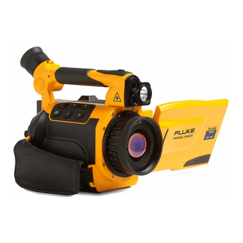
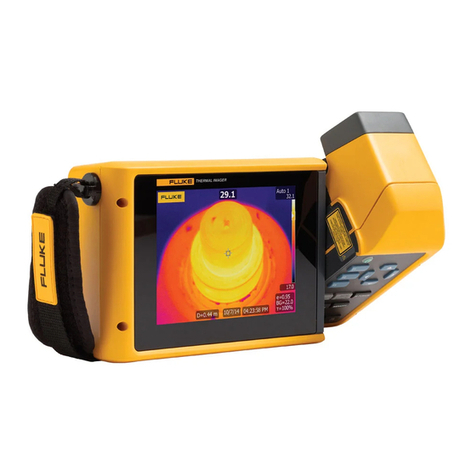
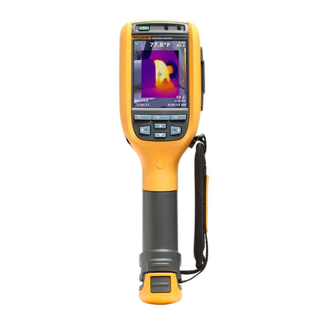
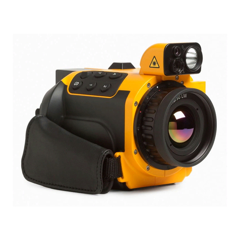
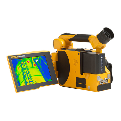
Fluke TiX870 User manual

TiX870, TiX875, TiX880, TiX885,
TiX875U, TiX885U, TiX1060, TiX1080
Thermal Imagers
Users Manual
11/2023 (English)
© 2023 Fluke Corporation. All rights reserved. Specifications are subject to change without notice.
All product names are trademarks of their respective companies.

LIMITED WARRANTY AND LIMITATION OF LIABILITY
Each Fluke product is warranted to be free from defects in material and workmanship under normal use and
service. The warranty period is 2 years and begins on the date of shipment. Parts, product repairs, and services
are warranted for 90 days. This warranty extends only to the original buyer or end-user customer of a Fluke
authorized reseller, and does not apply to fuses, disposable batteries, or to any product which, in Fluke's
opinion, has been misused, altered, neglected, contaminated, or damaged by accident or abnormal conditions
of operation or handling. Fluke warrants that software will operate substantially in accordance with its functional
specifications for 90 days and that it has been properly recorded on non-defective media. Fluke does not
warrant that software will be error free or operate without interruption.
Fluke authorized resellers shall extend this warranty on new and unused products to end-user customers only
but have no authority to extend a greater or different warranty on behalf of Fluke. Warranty support is available
only if product is purchased through a Fluke authorized sales outlet or Buyer has paid the applicable
international price. Fluke reserves the right to invoice Buyer for importation costs of repair/replacement parts
when product purchased in one country is submitted for repair in another country. Fluke's warranty obligation is
limited, at Fluke's option, to refund of the purchase price, free of charge repair, or replacement of a defective
product which is returned to a Fluke authorized service center within the warranty period.
To obtain warranty service, contact your nearest Fluke authorized service center to obtain return authorization
information, then send the product to that service center, with a description of the difficulty, postage and
insurance prepaid (FOB Destination). Fluke assumes no risk for damage in transit. Following warranty repair,
the product will be returned to Buyer, transportation prepaid (FOB Destination). If Fluke determines that failure
was caused by neglect, misuse, contamination, alteration, accident, or abnormal condition of operation or
handling, including overvoltage failures caused by use outside the product's specified rating, or normal wear and
tear of mechanical components, Fluke will provide an estimate of repair costs and obtain authorization before
commencing the work. Following repair, the product will be returned to the Buyer transportation prepaid and the
Buyer will be billed for the repair and return transportation charges (FOB Shipping Point).
THIS WARRANTY IS BUYER'S SOLE AND EXCLUSIVE REMEDY AND IS IN LIEU OF ALL OTHER
WARRANTIES, EXPRESS OR IMPLIED, INCLUDING BUT NOT LIMITED TO ANY IMPLIED WARRANTY OF
MERCHANTABILITY OR FITNESS FOR A PARTICULAR PURPOSE. FLUKE SHALL NOT BE LIABLE FOR
ANY SPECIAL, INDIRECT, INCIDENTAL, OR CONSEQUENTIAL DAMAGES OR LOSSES, INCLUDING LOSS
OF DATA, ARISING FROM ANY CAUSE OR THEORY.
Since some countries or states do not allow limitation of the term of an implied warranty, or exclusion or
limitation of incidental or consequential damages, the limitations and exclusions of this warranty may not apply
to every buyer. If any provision of this Warranty is held invalid or unenforceable by a court or other decision-
maker of competent jurisdiction, such holding will not affect the validity or enforceability of any other provision.
11/99
Fluke Corporation
P.O. Box 9090
Everett, WA 98206-9090
U.S.A.

iii
Table of Contents
Title Page
Introduction...................................................................................................................................................1
Product Overview ..................................................................................................................................1
How to Contact Fluke.............................................................................................................................1
Safety Information..................................................................................................................................2
Product Familiarization .................................................................................................................................2
Standard Packaging...............................................................................................................................2
Features.................................................................................................................................................4
Components and Controls..............................................................................................................4
Connection and Power Supply .......................................................................................................7
Rotatable Lens................................................................................................................................8
Touch Screen..................................................................................................................................9
Main Display Area.........................................................................................................................10
Shortcut Menu Area......................................................................................................................12
On-Screen Display........................................................................................................................14
Non Uniformity Correction (NUC) .................................................................................................14
Basic Operation ..........................................................................................................................................20
Turn On and Off the Imager.................................................................................................................20
Focus...................................................................................................................................................21
Capture and Save Images...................................................................................................................21
Digital Zoom.........................................................................................................................................21
System Menu..............................................................................................................................................22
Capture Mode......................................................................................................................................26
Single-capture ..............................................................................................................................26
Frame Interval...............................................................................................................................26
Timer.............................................................................................................................................27
Measurement Settings.........................................................................................................................28
Emissivity......................................................................................................................................29
Reflected Temperature .................................................................................................................30
Environment Temperature.............................................................................................................30

iv
Humidity........................................................................................................................................31
Distance........................................................................................................................................31
Transmittance...............................................................................................................................32
Base Temperature ........................................................................................................................32
View Mode...........................................................................................................................................33
PIP Mode......................................................................................................................................33
Measuring Tools...................................................................................................................................35
To add a ROI ................................................................................................................................36
ROI Operation ..............................................................................................................................38
Temperature Difference Calculation..............................................................................................41
Audible Alarm.......................................................................................................................................42
Non-Radiometric Videos......................................................................................................................43
Settings................................................................................................................................................44
Regional Intelligent Temperature Span Adjustment......................................................................47
TWB Technology...........................................................................................................................47
TFocus Technology.......................................................................................................................49
Thermal Image/Video Analysis....................................................................................................................50
Thermal Image.....................................................................................................................................51
Picture-in-Picture (PIP)........................................................................................................................53
Fully-Radiometric Videos.....................................................................................................................53
Automatically Name Scanned Files .....................................................................................................54
Add an Annotation ...............................................................................................................................54
Voice Annotation...........................................................................................................................54
Text Remark .................................................................................................................................55
Tag................................................................................................................................................55
SmartViewTM IR Software............................................................................................................................56
Download and Install the SmartView IR Software................................................................................56
Real-time View and Record Fully-Radiometric Video Streaming .........................................................57
Import and Save Thermal Image Files.................................................................................................58
Accessories.................................................................................................................................................59
Optional Lenses..........................................................................................................................................60
Maintenance ...............................................................................................................................................61
Clean the Product................................................................................................................................61
Lens Care............................................................................................................................................61
Battery Care.........................................................................................................................................62
Charge the Battery...............................................................................................................................62
Product Disposal..................................................................................................................................63
Radio Frequency.........................................................................................................................................63
Specifications..............................................................................................................................................64

1
Introduction
Product Overview
The TiX800/TiX1000 Series Thermal Imagers (the "Product" or "Imager") are diagnostic infrared
imaging cameras for use in many applications including equipment troubleshooting, diagnosis,
preventive and predictive maintenance, building diagnosis and energy efficiency assessment, and
product development or scientific research in various industries.
The Imager displays thermal images on a high-visibility, industrial-quality OLED touch screen. The
Imager can save images to internal memory or to a removable SD memory card. You can transfer the
images and data stored in internal memory, or on the memory card, to a PC using the Type-C USB
2.0 high-speed interface on the Imager and the USB port on a PC. You can transfer fully-radiometric
videos to a monitor, TV or other video display devices in real time with an HDMI interface.
The Imager includes a professional thermal image analysis software – SmartViewTM IR. The
SmartView IR is a high-performance, professional thermal image analysis software for thermal image
analysis, fully-radiometric video analysis and professional thermal image reporting.
The Imagers are powered by smart rechargeable lithium-ion batteries.
How to Contact Fluke
Fluke Corporation operates worldwide. For local contact information, go to our website: cn.fluke.com
(Chinese) or www.fluke.com (English)
To register your product, view, print, or download the latest manual or manual supplement, go to our
website.
Fluke Corporation
P.O. Box 9090
Everett, WA 98206-9090
+1-425-446-5500
fluke-[email protected]

TiX870, TiX875, TiX880, TiX885,
TiX875U, TiX885U, TiX1060, TiX1080
Users Manual
2
Safety Information
General Safety Information is in the printed Safety Information document that ships with the Product
and at www.fluke.com. More specific safety information is listed where applicable.
A Warning identifies conditions and procedures that are dangerous to the user. A Caution identifies
conditions and procedures that can cause damage to the Product or the equipment under test.
�Caution
Storage and/or continuously operating of the Imager in extreme ambient
temperature may result in temporary interruption of operation. In this case, let
the Imager stabilize (cool down or warm up) before you resume operation.
Product Familiarization
The manual explains functions and features for multiple models. Since different models have different
functions and features, not all of the information in the manual applies to your Imager.
Standard Packaging
To prevent damage during shipment, the Product is shipped in a specially designed package. Check
the Product carefully and inform the carrier of any damage.
When unpacking the Product, check the standard accessories listed in Table 1 and other ordered
parts listed on the packing list. If there is any shortage of parts, notify the nearest Fluke Technical
Service Center or the Service Center located in the place of purchase.
Figure 1 and Table 1 list the standard accessories for the Product. See Accessories for optional
accessories.

Thermal Imagers
Product Familiarization
3
Figure 1. Standard Accessories
Table 1. Standard Accessories
No. Description Quantity
a Hand strap 1
b The Thermal Imager 1
c Standard lens (installed) 1
d Lens cover (removable) 1
e Neck strap 1
f USB-SD reader 1
g AC adapter 1
h 2-bay battery charging base 1
i Rechargeable Li-ion battery, BP1000 3
j Included documentation, including a Safety Information, a
Quick Reference Guide, a Quality Certificate, and a
Warranty Card
1
Not shown
Type-C USB cable, 1 m 1
HDMI video cable, 1 m 1
High-speed SD card, 128 GB 1
Hard carrying case 1
12345
6
7
8
9
10

TiX870, TiX875, TiX880, TiX885,
TiX875U, TiX885U, TiX1060, TiX1080
Users Manual
4
Features
This section describes each component of the Product and the display. Please read this section
carefully before use.
Components and Controls
For the components and controls of the Imager, see Figure 2. Table 2 lists the features and functions
of each component.
Figure 2. Components and Controls
1
2
3 4
5 6 7 8
9
101112 13 14
1516
17
18
19
Front
Rear

Thermal Imagers
Product Familiarization
5
Table 2. Components and Controls
No. Item Description
a Hand strap Makes the Product easy to carry and comfortable to use.
b Hand strap anchor Use the anchor to secure the hand strap provided with the Product. The
hand strap can improve handheld stability and comfort.
c
AF (Auto Focus)
button
For live image screen, push AF, the Imager will automatically focus and
show a clear thermal image. See Focus.
d
Image capture button
The function of the button depends on the capture mode:
Single-frame mode:
1. In the live image screen, push once to freeze the screen.
2. In the image freeze screen, push once again to save the
thermal image to the specified storage medium (see Settings).
Frame Interval mode:
1. In the live image screen, push once to start the recording of
video at the frame rate you have set.
2. During recording a fully-radiometric video, push once again
to stop recording and freeze the screen. You can play back the
video.
3. Push once again or tap Save on the screen to save the
video in the cache to the specified storage medium.
In Timer mode:
1. Push once to start the recording of the fully-radiometric
video. Video frames are recorded to the timer you set.
2. Push once again to stop the recording and freeze the
screen. You can play back the video.
3. Push once again or tap Save on the screen, to save the
video in the cache to the specified storage medium (see Settings).
e Rotatable lens
Component 180° rotatable lens. See Rotatable Lens.
f Manual focus control
for infrared lens The focus control can be manually rotated clockwise or counterclockwise
to adjust the imaging clarity.
g Infrared lens Replaceable infrared lens assembly with standard lens. See Accessories
for details.
h Lens cover Retractable lens cover.
i LED torch/flashlight Use to identify the target in dark environment.

TiX870, TiX875, TiX880, TiX885,
TiX875U, TiX885U, TiX1060, TiX1080
Users Manual
6
Table 2. Components and Controls (cont.)
No. Item Description
j Visual light camera
lens 5 mega pixels
k Laser pointer Use to quickly aim at the target under test.
l Neck strap anchor Use the anchor to secure the neck strap provided with the Product.
m Power indicator
The power indicator goes off during normal operation.
The power indicator shows yellow-green during sleep/shutdown process
for reboot.
n
Power/Back button
Power button
- Push and hold for 2 s to turn on the Product, turn off the Product,
reboot the Product, or put the Product in Sleep mode according to
on-screen prompt.
- In Sleep mode, push to wake up the Product.
- In screen-off mode, briefly push to wake up the screen.
Back button
Return to previous menu. In image freeze interface, push to return
to live image screen.
Depending on the screen, has the same function as or
on the screen (in some cases, Back may need to be pressed twice).
This button is invalid on video recording screen.
o
Navigation keys
Push the arrow keys to move the cursor on the screen.
p
OK button Push OK (the middle of the navigation arrow keys) to select the option
where the cursor is located.
- On the System Menu screen, push OK to bring up the corresponding
sub-menu or activate the currently selected function.
- On the Home screen, push OK to bring up System Menus (same
function as ). See System Menu for more information.
- On the Gallery screen, push OK to bring up the functions associated
with the image where the cursor is located, including Analyze File
(Play when a video is selected), File Properties and Delete. See
Gallery for more information.
This button is invalid on video recording screen.
q Microphone Used to record a voice annotation.
r OLED touchscreen Touchscreen
s Speaker Used to play back audio files or voice annotations, and to sound alarms
for high/low temperature over-limit.

Thermal Imagers
Product Familiarization
7
Connection and Power Supply
Figure 3 shows the bottom of the Imager. Table 3 lists the features and functions of each component
on the bottom panel.
Figure 3. Bottom of The Product
Table 3. Bottom of The Product
No. Item Description
a Interface protective
cover
b HDMI interface Mini HDMI interface
c Type-C USB interface Type-C USB 2.0 interface
d Battery compartment
cover
e SD card slot Standard SD card slot
f Tripod mount Tripod standard threaded hole, UNC ¼"-20 mounting thread.
1 2 3 4
56

Thermal Imagers
Product Familiarization
9
Touch Screen
The screen is divided into: the Main Display Area in the middle, the Shortcut Menu Area containing
touch buttons on the left and right sides, and the System Menu Area superimposed on the bottom of
the Main Display Area, as shown in Figure 5.
Figure 5. Screen
Table 4.Screen
No. Item Description
a Shortcut Menu Area Shortcuts to the most used settings for changing parameters or selecting
functions and options.
b On-Screen Display See System Menu.
c
Main Display Area Shows videos/images. In addition, current measurements, environmental
data and equipment status show as On-Screen Display. The Main
Display Area displays different content depending on the current operating
mode and screen, as detailed in the relevant sections below.
d System Menu Area Shows when you tap system menu button, a system menu shows
depending on the operating environment. For more information, see
System Menu.
1 2 31
4

TiX870, TiX875, TiX880, TiX885,
TiX875U, TiX885U, TiX1060, TiX1080
Users Manual
10
Main Display Area
Figure 6. On-Screen Display
Note
Not all information is always shown on screen, to customize the information that
shows, see Settings.
Table 5.On-Screen Display
No. Description
a
On-Screen Display
The global maximum (Max), minimum (Min) and average (Avg) temperatures as well as point,
line and area temperatures for measurement and analysis are displayed based on system
settings.
b Bluetooth Indicator
Bluetooth status. When enabled, if a Bluetooth headset is connected, the Bluetooth headset
icon (with a Bluetooth symbol in the middle of the headset) shows.
c GPS Indicator
GPS status. See Settings for details.
d Battery Percentage
See Battery Care and Charge the Battery for details on batteries.
12 3 4 5 6
7
8
9
10
11
121315 14
17 16

Thermal Imagers
Product Familiarization
11
Table 5.On-Screen Display (cont.)
No. Description
e Battery Indicator
Shows the remaining battery power (the icon is red when the power is lower than 20 %). See
Battery Care and Charge the Battery for details on batteries.
f Upper Temperature Limit of Color Band
The highest temperature shown on the color band. See Settings for details.
g Super-Resolution Indicator
Super-resolution function status
h Laser Pointer Indicator
Laser pointer status
i HDMI Indicator
HDMI interface status
j Digital Camera Indicator
Digital camera status
k Temperature Span of Color Band
Color band representation (shows the relationship between temperature and color)
l Lower Temperature Limit of Color Band
The lowest temperature shown on the color band.
m Temperature Measuring Parameters
Relevant temperature measuring parameters are shown. See Measurement Settings for details.
n Location of the Maximum Temperature Point
Location of the maximum temperature point on full screen (a triangle cursor in red)
o
System Menu Buttons
Open the System Menu, where you can set capture mode, view mode, measurement settings,
alarms, and system settings.
See System Menu for more information on system settings.
p Location of the Minimum Temperature Point
Location of the minimum temperature point on full screen (an inverted triangle cursor in blue).
q Time and Date
Current clock date and time

TiX870, TiX875, TiX880, TiX885,
TiX875U, TiX885U, TiX1060, TiX1080
Users Manual
12
Shortcut Menu Area
Use the Touch keys in the Shortcut Menu Area to change parameters or select functions and options.
Figure 7 and Table 6 the features and functions of each component of the Shortcut Menu Area.
Figure 7. Shortcut Menu Area
Table 6. Touch Key Functions
No. Description
a
On-Screen Display
Show or hide the on-screen display.
See Figure 6 and Table 5 for details.
b
Non Uniformity Correction (NUC)
Tap NUC icon to execute the Non Uniformity Correction function. See Non Uniformity
Correction (NUC) for details.
c
Measuring Tools
The Imager comes with measuring and analysis tools. See Measuring Tools for details.
1
2
3
4 8
9
7
6
5

Thermal Imagers
Product Familiarization
13
Table 6. Touch Key Functions (cont.)
No. Description
d
System Settings
Tap to enter the System Settings interface. For more information, see Settings.
e
Temperature Span Mode
Switches between Auto Span and Manual Span modes.
For more information, see Temperature Span Mode.
f
Laser Pointer
Tap and hold to turn on the Laser Pointer and release the icon to turn off the Laser
Pointer. For more information, see Laser Pointer.
g
Color Palettes
Tap to enter the submenu for quickly switching palettes, you can choose palettes, and set color
alarms (isotherm).
For more information, see Color Palettes.
h
Gallery
Tap to enter the Gallery to browse or analyze thermal images or fully-radiometric videos.
For more information, see Gallery.
i
System Menu Keys
On the System Menu Area, you can set up the capture mode, measurement settings, view
mode, temperature measurement area, audio alarm, non-radiometric videos, and system
settings.
For more information, see System Menu.

TiX870, TiX875, TiX880, TiX885,
TiX875U, TiX885U, TiX1060, TiX1080
Users Manual
14
On-Screen Display
Enable or Disable On-screen Display
Tap to display or hide all on-screen display.
When the center of the on-screen display icon on the screen is yellow ( ), the on-screen display
shows in real time; when the center of the icon is white ( ), the information on the screen is hidden.
You can customize the on-screen display, see Settings for specific operations.
Non Uniformity Correction (NUC)
Non Uniformity Correction (NUC) is used to adjust for small detector drift that occurs when the
application scenario and environment changes. In general, the Imager's heat will interfere with its
temperature readings. To improve accuracy, the Imager measures the temperature of its own optics
and then adjusts the image based on these readings. The NUC adjusts the gain and offset for each
pixel to create higher quality, more accurate images.
The NUC is automatically done at startup, when the measurement range is changed, or when the
ambient temperature changes.
You can do NUC manually when you take critical measurements. For example, you may need to
perform manual calibration to improve temperature measurement accuracy before starting to record a
fully-radiometric video.
Temperature Span Mode
The Imager provides these modes: Auto Span ( ) and Manual Span ( ).
In Auto Span mode, the upper or lower limit of the temperature span is the global maximum or
minimum temperature, and the temperature span is automatically adjusted.
In Manual Span mode, the background of the upper and lower temperature limits on the color band is
gray, and the span is adjustable. When there is no gray background on the upper and lower
temperature limits on the color band, the span is locked. Tap the temperature limit to switch between
locked and adjustable states, as shown in Figure 8.
Note
In Manual Range ( ) mode, if the wheel does not appear on the screen, check the
on-screen display settings, and make sure on-screen display is enabled ( ). For
on-screen display settings, see Shortcut Menu Area.

Thermal Imagers
Product Familiarization
15
Figure 8. Adjust Temperature Span Manually
To adjust temperature span manually:
1. Tap temperature span icon so that it appears as to switch to Manual Range mode.
2. Tap the upper and lower temperature limits as needed so that their backgrounds are grayed out.
3. Scroll the wheel up or down to adjust the limits.
4. When the upper and lower temperature limits on the color band both have gray background, both
limits can be adjusted at the same time.
5. When the upper temperature limit of the color band has gray background and the lower limit has
no background color, the upper limit can be adjusted, and the lower limit remains unchanged.
6. When the lower temperature limit of the color band has gray background and the upper limit has
no background color, the lower limit can be adjusted, and the upper limit remains unchanged.
7. When there is no gray background both for the upper and lower temperature limits on the color
band, they are locked, and the upper and lower limits cannot be adjusted.
See Specifications for more information on minimum temperature span.
Upper temperature limit
Wheel
Lower temperature limit

TiX870, TiX875, TiX880, TiX885,
TiX875U, TiX885U, TiX1060, TiX1080
Users Manual
16
Laser Pointer
Tap and hold Laser Pointer key to turn on the Laser Pointer to locate the target to be measured;
release the key to turn off the Laser Pointer.
When the laser is on, the laser icon is blue ( ), and the laser indicator ( ) is shown on the
screen; when the laser is off, the icon is white ( ).
�Warning
To prevent eye damage or personal injury:
Do not look into the laser. Do not point laser directly at persons or animals
or make it reflected indirectly from reflective surfaces.
Do not disassemble the Product. The laser beam is dangerous to eyes.
Have the Product repaired only through an approved technical service.
Color Palettes
With the palette function, you can select palettes and set color alarms (isotherms).
To choose a palette:
1. Tap (right Shortcut Menu Area). The palette menu shows and includes:
•Iron ( )
•Rainbow ( )
•Grey ( )
•Blue ( ).
Note
A hint for each button shows on the display. To view hints, use navigation keys
to move the cursor between the icons. The function/status prompts for the button, as
shown below.
2. Tap an icon to select a palette directly or tap . All palette options are shown.
This manual suits for next models
7
Table of contents
Other Fluke Thermal Camera manuals

Fluke
Fluke Ti40FT-20 User manual

Fluke
Fluke TiR1 User manual

Fluke
Fluke Ti300 User manual

Fluke
Fluke TiR32 Instruction manual

Fluke
Fluke TiS10 Original instructions

Fluke
Fluke TiS55+ User manual

Fluke
Fluke TiR105 User manual

Fluke
Fluke Ti20 User manual

Fluke
Fluke Ti50FT-20 User manual

Fluke
Fluke Ti9 Instruction manual

Fluke
Fluke Ti27 Instruction manual

Fluke
Fluke tix640 User manual

Fluke
Fluke Professional Ti300 PRO User manual

Fluke
Fluke tix660 User manual

Fluke
Fluke ThermoView TV40 Series User manual

Fluke
Fluke TiX500 User manual

Fluke
Fluke tix640 User manual

Fluke
Fluke Ti105 User manual

Fluke
Fluke PTI120-9 User manual

Fluke
Fluke Ti90 User manual