Verity Installation Manual 3
VERITY INSTALLATION MANUAL
General Information ��������������������������������������������������������������������������������������������������� 4
Safety & Support ��������������������������������������������������������������������������������������������������������� 5
Installation Tools ���������������������������������������������������������������������������������������������������������� 6
Staging & Installation ������������������������������������������������������������������������������������������������ 7
Stand Alone Units
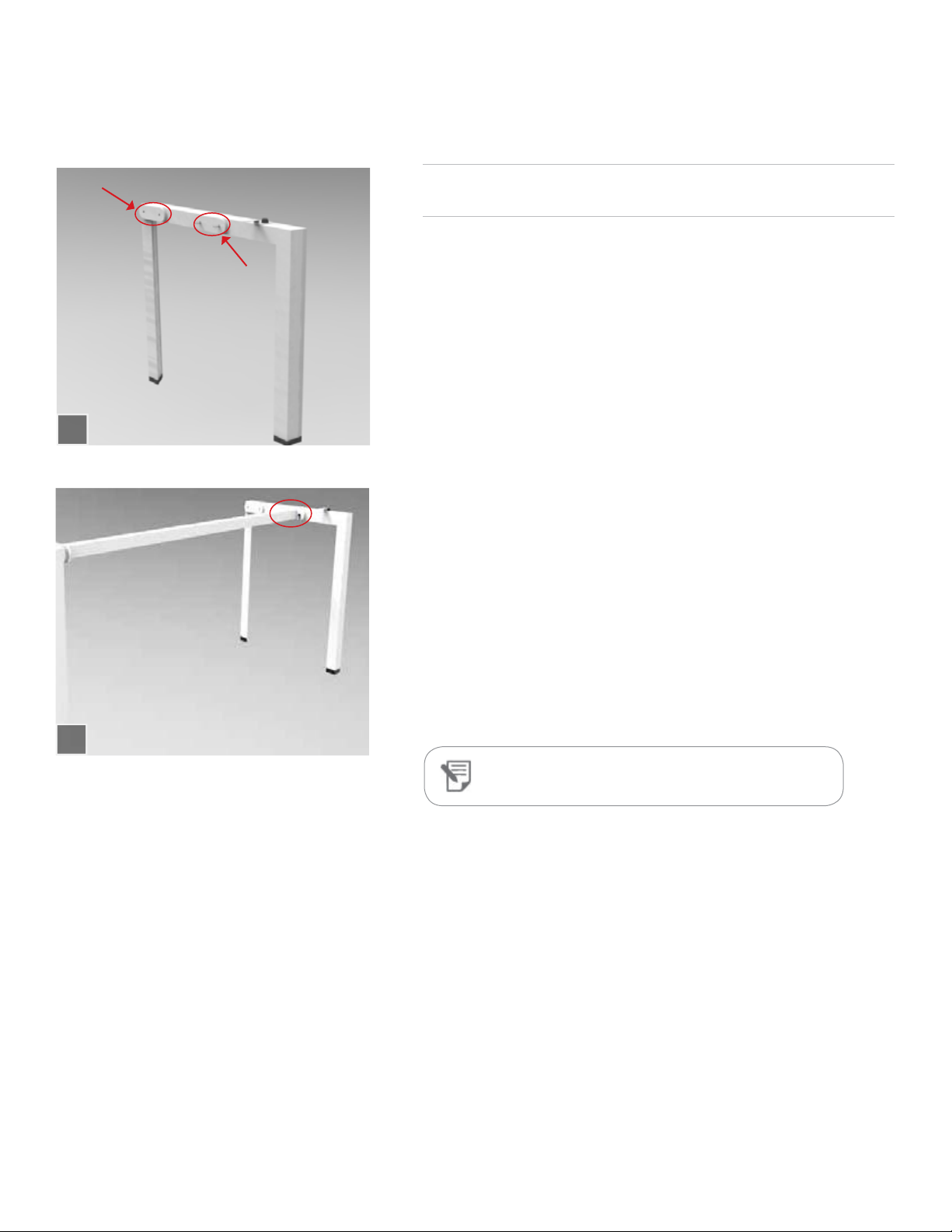
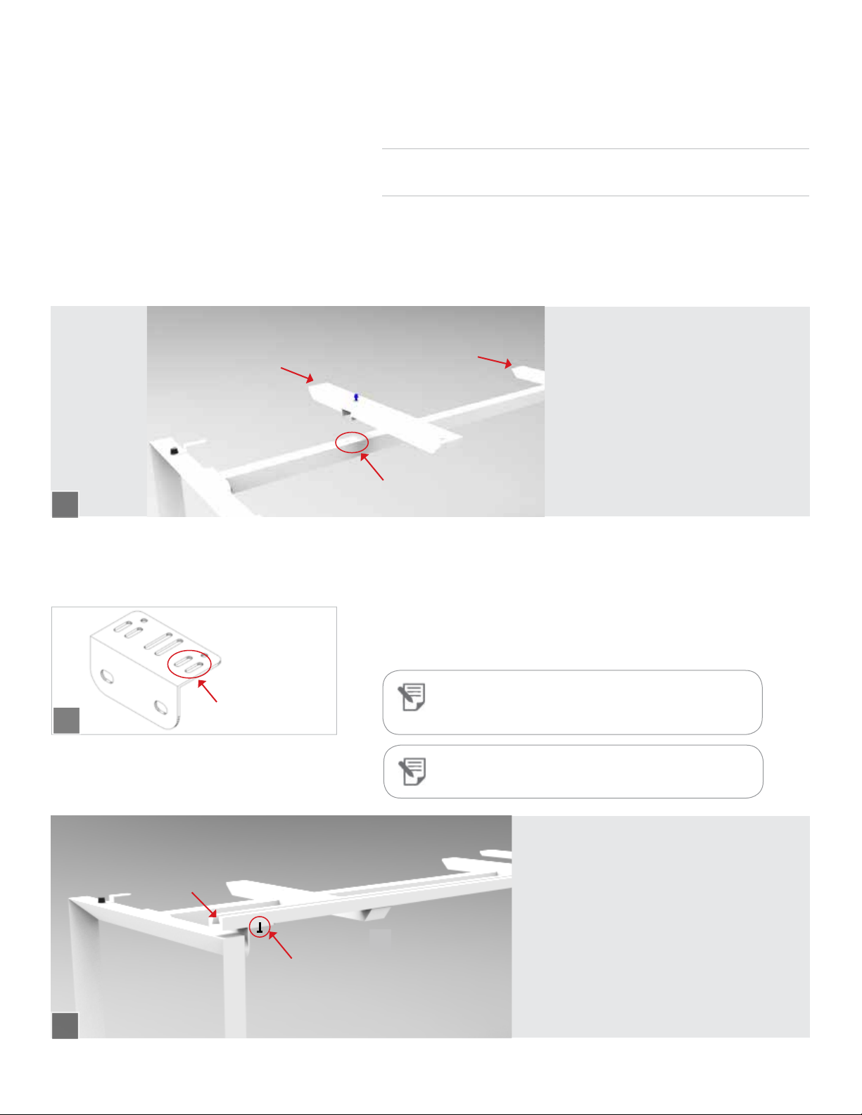
Single-Sided Structure �������������������������������������������������������������������������������������������� 8
Double-Sided Structure ����������������������������������������������������������������������������������������� 12
Elements
Single-Sided Structure ������������������������������������������������������������������������������������������� 17
Double-Sided Structure ���������������������������������������������������������������������������������������� 22
Electrical
Definitions ������������������������������������������������������������������������������������������������������������������� 28
Power Installation ���������������������������������������������������������������������������������������������������� 29
Power Trough: Single-Sided �������������������������������������������������������������������������������� 31
Power Trough: Double-Sided ����������������������������������������������������������������������������� 33
Power Jumpers ����������������������������������������������������������������������������������������������������������� 35
Worksurfaces
Return Worksurface: Installing to the Beam ����������������������������������������������� 36
Return Worksurface: Installing to the Center Leg ����������������������������������� 37
Worksurface ��������������������������������������������������������������������������������������������������������������� 38
Track Spacer ����������������������������������������������������������������������������������������������������������������39
Grommet ���������������������������������������������������������������������������������������������������������������������� 40
Accessories
Track-Mounted Tackboard ������������������������������������������������������������������������������������ 41
Track-Mounted Glass ���������������������������������������������������������������������������������������������� 42
Open Shelf ������������������������������������������������������������������������������������������������������������������� 43
Monitor Arm �������������������������������������������������������������������������������������������������������������� 44
Storage
Over Worksurface Storage: With Cabinet Support �������������������������������� 45
Over Worksurface Storage: With Column Base Support �������������������� 46