GE;K-730~
Low
Voltage
Power
Circuit
Breakers
MANUAL
MAINTENANCE
- .
~
CLOSING
OF
ELECTRICAL
BREAKE~S
· An electrical
breaker
may be closed manually
by _means of the maintenance handle furnished
'with the
breaker.
·
·
To
observe
~e
operation of the
breaker
with- ·
out
power, with the
break~r
open and
springs
discharged, proceed
as
follows:
1. · Charge the·closing
spring
with tbe main~
te~ance
han~e
(1,
Fig.
3) until the indica-
tor
rea~
"charged": .
2. Continue to
operate
the.maintenance handle
until the
breaker
close~.
3.
Open. ·the
breaker
by . pushing· the
trip
.
· _·button(4, "
F~1t.
2)~
. . .
ELlCl'.RICAL
CLOSIN~
The
-
electrical
control s·ystem ·
is
comprised
of-an- X relay, two double_contact mechanically
operated
switches (F anq G), a push outton closing
switch
and _any means
for
remote closing which
the
user
may incorporate into the
system.
When
voltage
is
.
.first
.applied to the
breaker,
(before any
closing s'ignal
is
given) the motor
is
energized
through two of the X relay contacts and the two
a
·.
switch
contacts.· The-.motor then
compresses
the closing springs to the
"pre-charged"
position
at
which point the mechanically operated F and G
·
switc~es
are
ope_
rated.
This ope_
ns
the G contacts,
stop~mg the motor, and closestheF contacts,whicp
readies
the
system
for
the. actual closing of the
breaker
.. When the push button
~r
remote switch ·
signals
·
for
a closing operation, the X relay coil
is
e~ergized, operating the X contacts. This
seals
·
in
the
X
relay
and energizes the.motor once again
and
tl?,e
closing operation
takes
place. . .
QUt:CK CLOS.E
FOR ELECTRICAL BREAKERS
. Functionally, the ·quick close mechanismdiffers
from
the
standard
electrical
mecbanism
in
that
the
pre-charge
operation
is
extended ·to completely
charge
the closing
springs.
At
theendofthe
charg-
ing oper~tion,
w~ch
takesapproximately5seconds,
a
latch
plate
engages the prop
roller
to
prevent
_theclosing springs from discharging. .
. With
the
closing
springs
fully charged the
breaker
is
ready
for
a closing operation upon
release
of the prop
roller.
This
may be accom-
plished
either
m~ually,
by
depressi
.ng the closing
.
lever
on. the
breaker,
or
electrically
by closing
the
remote
closing switch. Upon the
release
of
. the prop
roller
the closing
springs
discharge and
close
the
breaker
in the
same
manner
as
on the
·
stan~ard
electrical
breaker.
·
Wi~
. control voltage appli~d, :the motor
is
·.·
energized
through the .G switch. contacts, ·and
charges
the closing springs. When the
springs
4
reach
the
fully charged position; the mechanically
operated
switches
operate,
reversing
their
coniact:S.
Upon
operation
of
these
switches the
motor.
1s
stopped by the.opening of theGswit~h. The closing
of the F
switch
prepares
the
bre
.
aker
for- a
closing
operation.
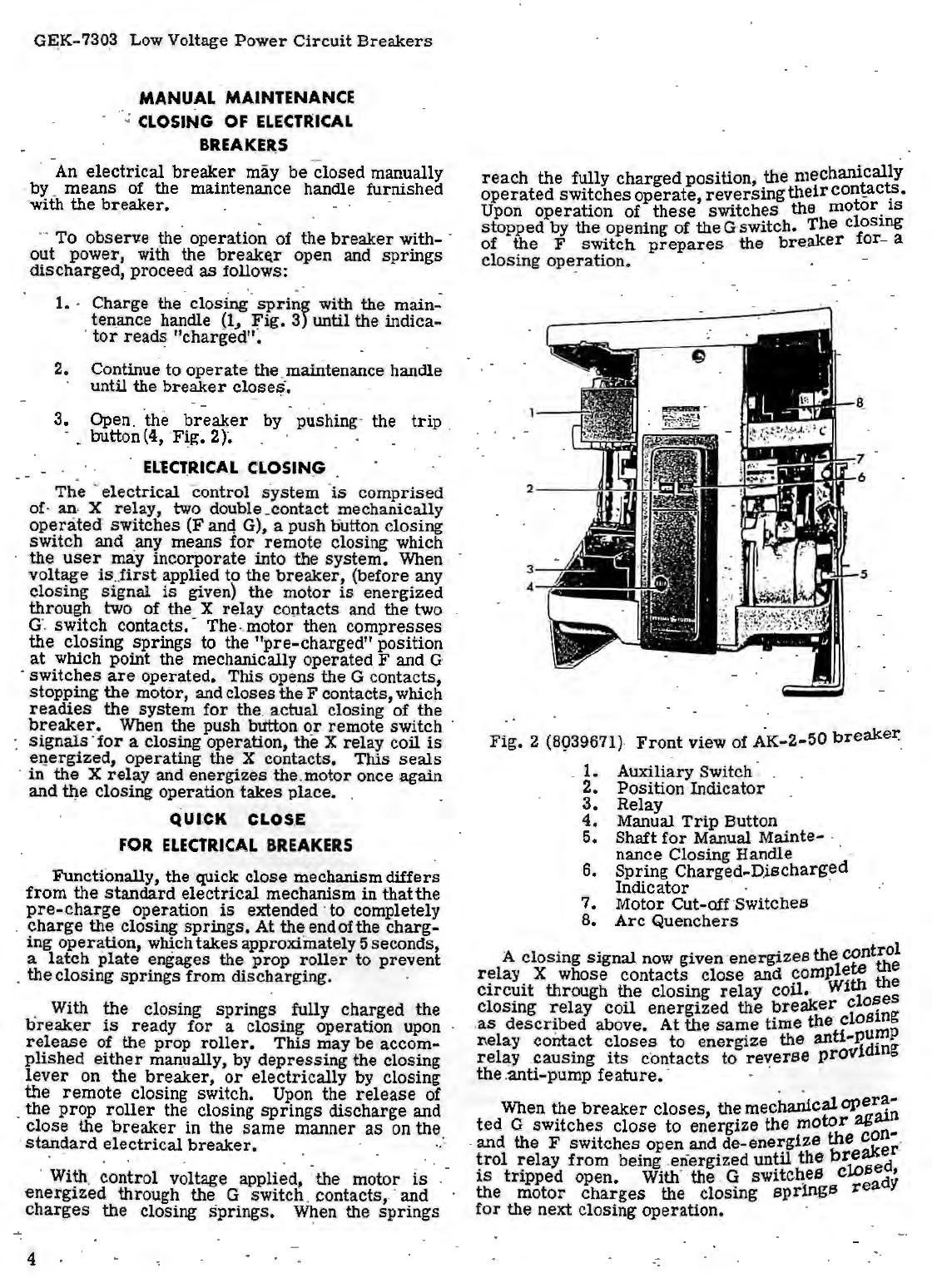
Fig.
2 (8939671)-
Front
view of AK-2-50
bre~e~
.
1.
Auxiliary Switch· .
2. Position Indicator
3.
Relay
4. Manual
Trip
Button
5. Shaft
for
Manual Mainte- ·
nance Closing Handle · ·
6.
Spring
Charged-Discharged
Indicator · ·
7. Motor Cut-off·Switches
8.
Arc
Quenchers
A closing
signal
now given·
energizes
the
cont;;
relay
X whose contacts
close
and
comple:
the
circuit
through the closing
relay
coil.
. Wi 8
closing
relay
coil energized the
breaker
clo~eg
.
as
descr~bed above. At the
same
time
the·
clos:P
l\elay contact
closes
to energize the anti-pU
rel~y .causing
its
c·
ontacts
to re\_'erse
providing
the.anti-pump
feature.
·
When the
breaker
closes,
themechanical
oper~~
ted
G switc
hes
close
to energize the
motor
ag~-
. and the F switches open and de-ene:1;gize
the
:er-
·
trol
relay
from
being .energized
until
the
brtsed
is
tripped
open. With' the .G switc~es c
dy'
the motor
charges
the closing
sprlngs
rea
for
the next closing operation.