Bestimmungsgemässe Verwendung
Angetriebene Industriearmaturen sind ausschliesslich dazu
bestimmt, zugelassene Medien innerhalb der zugelassenen
Druck- und Temperaturgrenzen in einem Rohrleitungssystem für
industrielle Zwecke abzusperren, durchzuleiten oder den
Durchfluss zu regeln. Die maximale Betriebsdauer beträgt 25
Jahre.
Bedeutung der Signalwörter
WARNUNG!
Möglicherweise drohende Gefahr!
Bei Nichtbeachtung drohen schwere Verletzungen.
VORSICHT!
Gefährliche Situation!
Bei Nichtbeachtung drohen leichte Verletzungen.
HINWEIS!
Situation vermeiden!
Bei Nichtbeachtung droht Sachschaden.
Abkürzungen
Abkürzungen
FC Wirkungsweise Federkraft schliessend
FO Wirkungsweise Federkraft önend
DA Wirkungsweise Federkraft doppeltwirkend
DN Nenndurchmesser
PA Pneumatischer Antrieb
EA Elektrischer Antrieb
dEA Elektrischer Smarter Antrieb
Allgemeine Sicherheitshinweise
Betriebsanleitung beachten!
Die Betriebsanleitung ist Teil des Produkts und ein wichtiger
Bestandteil im Sicherheitskonzept. Nichtbeachtung kann zu
schweren Verletzungen führen.
►Betriebsanleitung lesen und befolgen.
►Betriebsanleitung stets beim Produkt verfügbar halten.
►Betriebsanleitung an alle nachfolgenden Verwender des
Produkts weitergeben.
Inbetriebnahme und Benutzung nur durch Fachpersonal!
►Produkt und Zubehör nur von Personen in Betrieb nehmen
lassen, die die erforderliche Ausbildung, Kenntnis oder
Erfahrung haben.
►Personal regelmässig in allen zutreenden Fragen der örtlich
geltenden Vorschriften für Arbeitssicherheit und Umwelt-
schutz, vor allem für druckführende Rohrleitungen,
unterweisen.
Lagerung und Transport!
Das Produkt muss sorgfältig behandelt, transportiert und gelagert
werden. Hierzu sind folgende Punkte zu beachten:
►Produkt in ungeöneter Originalverpackung transportieren
und
►lagern.
►Produkt vor schädlichen physikalischen Einflüssen wie Licht,
Staub, Wärme, Feuchtigkeit und UV-Strahlung schützen.
►Produkt und seine Komponenten dürfen weder durch
mechanische, noch durch thermische Einflüsse beschädigt
werden.
►Produkt in Anlieferungszustand lagern.
►Produkt vor Installation auf allgemeine Schäden untersuchen.
VORSICHT!
Nur Originalteile verwenden!
Materialschaden und/oder Verletzungsgefahr durch nicht
kompatible Ersatzteile.
►Nur original-Ersatzteile von GF Piping Systems verwenden.
►Ersatzteile mit den Angaben gemäss Typenschild bestellen.
►Keine defekten Ersatzteile einsetzen.
WARNUNG!
Beschädigte Produkte nicht verwenden!
Verletzungsgefahr oder Sachschaden durch Verwendung von
defekten oder beschädigten Produkten.
►Kein beschädigtes oder defektes Produkt verwenden.
►Beschädigtes oder defektes Produkt sofort austauschen.
VORSICHT!
Dichtungen undicht!
Verletzungsgefahr durch austretendes Medium wegen
beschädigten oder gealterten Dichtungen.
►Dichtungen möglichst kühl, trocken und dunkel lagern.
►Dichtungen vor dem Einbau auf mögliche Alterungsschäden
wie Anrisse und Verhärtungen prüfen.
►Dichtungen regelmässig prüfen und ggf. ersetzen.
Warnhinweise zu Antrieben allgemein
WARNUNG!
Einklemmen während Betätigung!
Verletzungsgefahr durch Einklemmen von Körperteilen!
►Finger, Hand oder andere Körperteile niemals in den
Önungsbereich des Ventils halten, während der Antrieb aktiv
ist.
VORSICHT!
Nicht kompatibler Antrieb!
Fehlerhaftes Önen/Schliessen oder erhöhter Verschleiss durch
Nichtbeachten der Ventil- und Antriebsspezifikationen.
►Spezifikationen von Ventil und Antrieb beachten.
►Nur für das Ventil vorgesehenen Antrieb montieren.
WARNUNG!
Bewegliche Teile der Handbetätigung!
Während des Betriebs dürfen Körperteile nicht im Bewegungsra-
dius der Handbetätigung geführt werden
►Bewegungsradius der Handbetätigung beachten.
Warnhinweise zu elektrischen Antrieben
WARNUNG!
Verletzungsgefahr oder Gefahr von Beschädigungen.
Mögliche Stromschläge oder Beschädigung des Antriebs durch
Kurzschluss.
►Antrieb nur gemäss Anschlussdiagramm in der Bedienungs-
anleitung anschliessen.
►Draht nur durch die mitgelieferten Kabelverschraubungen
anschliessen.
►Die vorhandene Schutzerde (PE) muss auf der Hauptplatine
angeschlossen und 2,5 cm länger sein als die Spannungslei-
tungen (letzter Kontakt bei Ausfall der Kabelverschraubung).
►Für den Durchmesser der Anschlussdrähte geeignete isolierte
Ringklemme verwenden (für 0,5 - 1,5 mm2Drähte,
Ringdurchmesser 0,5 cm).
Intended use
Actuated industrial valves are exclusively intended to shut o,
pass through or control the flow of approved media within the
approved pressure and temperature limits in a piping system for
industrial purposes. The maximum time of operation is 25 years.
Meaning of the signal words
WARNING!
Possible danger!
Non-observance may result in serious injuries.
CAUTION!
Dangerous situation!
Non-observance may result in minor injuries.
NOTICE!
Avoid the situation!
Non-observance will lead to a risk of damage to property.
Abbreviations
Abbreviations
FC Function Failsafe Closed
FO Function Failsafe Open
DA Function Double Acting
DN Nominal Diameter
PA Pneumatic Actuator
EA Electric Actuator
dEA Electric Smart Actuator
General safety information
Observe instruction manual!
The instruction manual is part of the product and an important
component within the safety concept. Non-observance may lead to
severe injuries.
►Read and observe instruction manual.
►Always have instruction manual available by the product.
►Give instruction manual to all subsequent users of the product.
Commissioning and use by qualified personnel only!
►Product and accessories shall only be put into operation by
persons who have the required training, knowledge or
experience.
►Regularly instruct personnel on all questions regarding the
local regulations applying to occupational safety and
environmental protection, especially for pressurized pipes.
Storage and transport!
The product must be handled, transported and stored with care.
Please note the following points:
►Transport and store the product in its unopened original
packing.
►Protect the product from harmful physical influences such as
dust, heat, humidity and UV radiation.
►The product and its components must not be damaged either
by mechanical or thermal influences.
►Store the product in the delivery state.
►Check the product for general damage prior to installation.
CAUTION!
Use only original parts!
Risk of material damage and/or injury due to non-compatible
spare parts.
►Only use original spare parts from GF Piping Systems.
►Order spare parts using the information on the type plate.
►Do not use defective spare parts.
WARNING!
Do not use damaged products!
Danger of injury or material damage through the use of defective
or damaged products.
►Do not use a damaged or defective product.
►Replace any damaged or defective products immediately.
CAUTION!
Leaking gaskets!
Danger of injury by leaking medium due to damaged or aged
gaskets.
►Store gaskets if possible in a cool, dry and dark place.
►Before installing them, the gaskets have to be checked on
possible ageing damages, such as fissures and hardening.
►Regularly check the gaskets and replace, where necessary.
Warnings for actuators in general
WARNING!
Pinching during operation!
Risk of injury by pinching of body parts!
►Never enter fingers, hands or other body parts into the
opening of the valve when the actuator is active.
CAUTION!
Non-compatible actuator!
Faulty opening/closing or increased wear due to non-observance
of the valve and actuator specifications.
►Observe the specifications for the valve and actuator.
►Only install the actuator intended for the valve.
WARNING!
Moving parts of the manual override!
During operation, body parts must not be introduced into the
movement radius of the manual override
►Observe the movement radius of the manual override.
Warnings for electric actuators
WARNING!
Risk of injury or damage.
Possible electric shocks or damage to the actuator by short circuit.
►Connect the actuator only according to the connection diagram
of the instruction manual.
►Connect wire only via the included cable glands.
►The available protective earth (PE) must be connected to the
main circuit board and 2.5 cm longer than the power lines (last
contact in case of failure of the cable gland).
►Use insulated ring terminals suitable for the diameter of the
connection wires (for 0.5 - 1.5mm2wires, ring diameter
0.5cm).
WARNING!
Risk of injury due to faulty power supply!
Do not connect faulty or mixed power potentials or power sources.
►Either connect 230VAC or 24VDC (depending on the actuator
type) to the return relay.
►Make sure that the power supply is only provided from a single
power source.
WARNUNG!
Verletzungsgefahr durch falsche Spannung!
Keine falschen oder keine gemischten Spannungspotenziale oder
Spannungsquellen anschliessen.
►Entweder 230 VAC oder 24 VDC (Je nach Antriebs-Typ) mit den
Rückführrelais anschliessen.
►Sicherstellen, dass Spannung nur aus einer einzigen
Spannungsquelle angeschlossen wird.
WARNUNG!
Verletzungsgefahr oder Beschädigung bei abgenommenem
Deckel!
Vor Entfernen oder Önen des Antriebs-Deckels besondere
Sicherheitsmassnahmen beachten.
►Wenn möglich immer Stecker für Speise- und Steuerspannung
abziehen.
►Einstellarbeiten bei Antrieb unter Strom nur mit isolierten
Werkzeugen durchführen.
►Während dem Betrieb des Antriebes nicht in bewegliche
Bauteile fassen.
►ESD-Empfindliche Bauteile nicht anfassen und gegebenenfalls
Schutzvorkehrungen treen.
VORSICHT!
Beschädigung oder Kurzschluss des Stellantriebs durch
Wassereintritt!
Eindringende Feuchtigkeit oder Fremdkörper im Antrieb
vermeiden.
►Kabelführung so montieren, dass sie nicht nach oben zeigt.
►Steckkontakte mit Dichtungen versehen.
►Regelmässig korrekten Sitz und Funktionsfähigkeit aller
Dichtungen prüfen.
HINWEIS!
Signalfehler und Vorzeitiger Komponenten-Verschleiss!
Erneutes Anfahren der gesetzten Position bei nicht dauerhaftem
Positionssignal.
►Signal zur Positionsansteuerung auch nach Erreichen der
gesetzten Position belassen.
►Zur Vermeidung des Signalverlustes können die Eingänge
AUF/ZU als Wechsler angeschlossen werden.
WARNUNG!
Gefahr durch sich Drehende Handnotbetätigung!
Die eingesteckte Handnotbetätigung kann durch unbeabsichtigte
Betätigung des Antriebs gefährliche Drehbewegungen ausführen.
►Während der Verwendung der Handnotbetätigung Antrieb
durch Entfernen des Gerätesteckers stromlos schalten.
►Handnotbetätigung bei Nichtverwenden vom Antrieb entfernen.
Warnhinweise zu pneumatischen Antrieben
VORSICHT!
Falscher Anschluss!
Bei nicht fachgerechtem Anschluss kann unkontrolliert Steuerluft
austreten, wodurch der pneumatische Antrieb in seiner Funktion
beeinträchtigt wird.
►Informationen zu korrektem Anschluss in der Betriebsanlei-
tung befolgen.
►Die Steuerluftanschlüsse sind am Antrieb markiert.
►Unkontrolliertes Austreten der Steuerluft durch korrektes
Anschliessen vermeiden.
VORSICHT!
Schlechte Steuerluft-Qualität!
Vorzeitiger Verschleiss durch unzureichende Steuerluft-Qualität.
►Verunreinigungen und Reinheit der Steuerluft nach ISO 8573-1
beachten.
VORSICHT!
Verstopfte Önungen!
Durch Verstopfen der Anschlussönungen (Be- und Entlüftungs-
önungen) kann die Bewegung des Antriebs gehemmt werden.
►Nicht angeschlossene Steuerluft-Anschlussönungen mit
Filterelementen vor Ansaugen von Schmutz schützen.
WARNUNG!
Unvorhersehbare Bewegungen des Antriebs!
Verletzungsgefahr durch Einquetschen.
►Antrieb nach Abklemmen der Steuerluft-Leitungen und in
Sicherheitsstellung montieren oder demontieren.
WARNUNG!
Vorgespannte Federn!
Verletzungsgefahr durch rausspringende Bauteile.
►Antriebe mit FC und FO Funktion dürfen vom Kunden nicht
geönet, bzw. zerlegt werden.
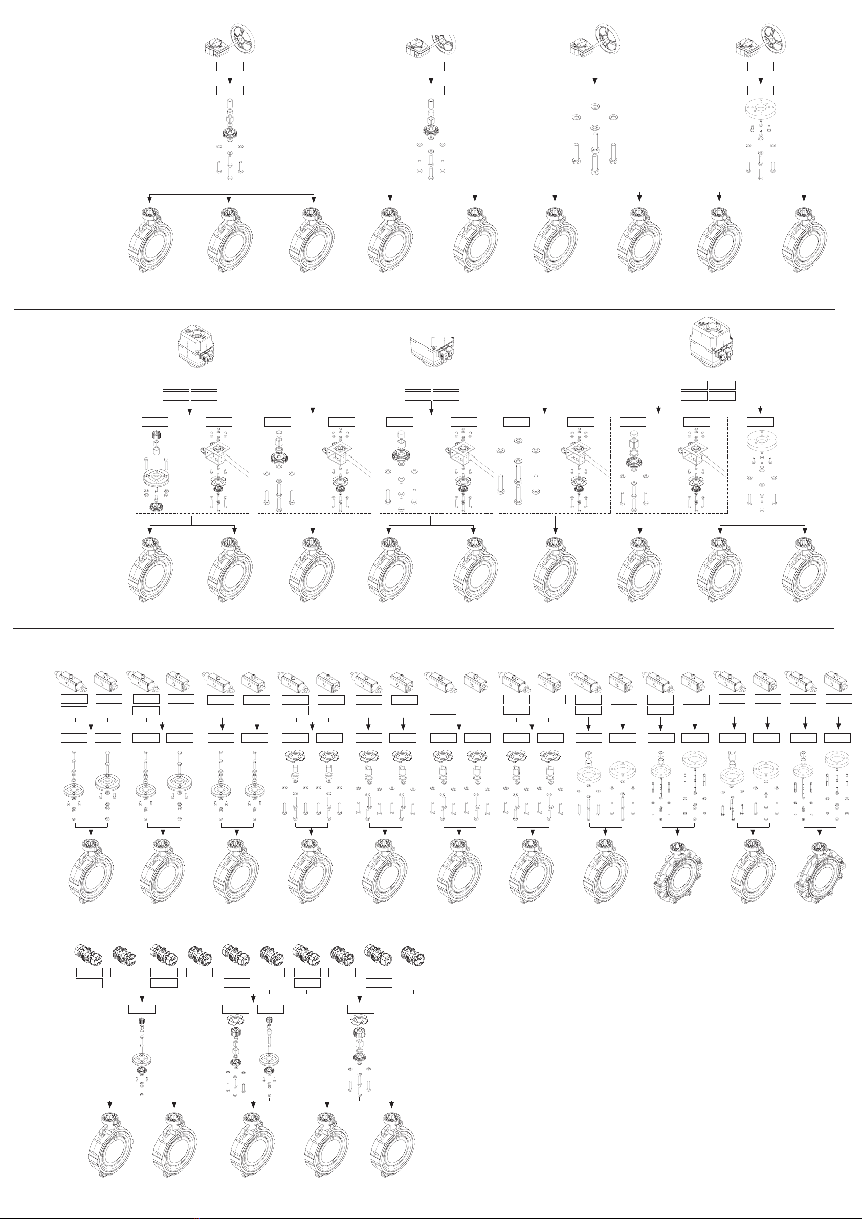
Montagevorgang gemäss nachfolgenden Zusammen-
stellungen
HINWEIS!
Die Absperrklappen Typ 567/578 in den Dimensionen DN50 bis
DN200 haben einen F07 Kopansch entsprechend ISO 5211.
VORSICHT!
Schrauben sichern!
Schrauben mit dem vorgegebenen Drehmoment festziehen und mit
Schraubensicherung sichern, da sie sich ansonsten lösen können.
►Beigelegte Schrauben des Zwischenelementes mit einem
Anzugsmoment von 10 Nm festziehen und mit «Loctite 243»
oder gleichwertig sichern.
Vorgehen
1. Antrieb und Ventil in gleiche Stellung bringen.
HINWEIS!
Die Indexierungen von Antrieb und Armatur müssen beim
Zusammenbau übereinstimmen.
2. Zwischenelement oder Handbetätigung mit mitgelieferten
Schrauben auf Antrieb befestigen.
3. Antrieb durch Zwischenelement oder Handbetätigung an Ventil
befestigen.
WARNING!
Risk of injury or damage when the lid is removed!
Observe special safety measures prior to removing or opening the
actuator lid.
►If possible, always detach the plugs for the power supply and
control power.
►Only use insulated tools for adjustment activities on actuators
connected to the power supply.
►Do not reach into movable components while the actuator is
operating.
►Do not touch ESD sensitive components and take precautions if
necessary.
CAUTION!
Damage or short circuit of the actuator due to water ingress!
Prevent moisture or foreign bodies from entering the actuator.
►Mount the cable routing, so it does not point upwards.
►Equip pin connectors with gaskets.
►Regularly check the correct position and functioning of all
gaskets.
NOTICE!
Signal error and premature component wear!
Repeated drive to the set position if the position signal is not
permanent.
►Maintain the signal for the drive to the position also after
reaching the set position.
►To prevent signal loss, the OPEN/CLOSE inputs can be
connected as changeover contacts.
WARNING!
Danger from rotating emergency manual override!
The inserted emergency manual override may perform dangerous
rotating movements if the actuator is activated unintentionally.
►During the use of the emergency manual override, switch o
the power of the actuator by removing the device plug.
►When not in use, remove the emergency manual override from
the actuator.
Warnings for pneumatic actuators
CAUTION!
Incorrect connection!
With incorrect connection, control air can escape uncontrolled,
which would impede the function of the pneumatic actuator.
►Follow the instructions for correct connection in the instruction
manual.
►The control air connections are marked on the actuator.
►Prevent the uncontrolled escape of the control air by correct
connections.
CAUTION!
Poor control air quality!
Premature wear due to insucient control air quality.
►Observe the poisoning and impurity of the control air according
to ISO 8573-1.
CAUTION!
Clogged openings!
Clogging of the connection openings (ventilation and exhaust
openings) can obstruct the movement of the actuator.
►Use filter elements to prevent unconnected control connection
openings from collecting dirt.
WARNING!
Unintended movement of the actuator!
Risk of injury by crushing.
►Install and uninstall the actuator after disconnecting the
control air lines and while in the safety position.
WARNING!
Pre-loaded springs!
Risk of injury by components jumping out.
►Actuators with FC and FO function must not be opened or
disassembled by customers.
Installation process according to the following
configurations
NOTE!
The butterfly valves type 567/578 in the dimensions DN50 to
DN200 have a F07 interface according to ISO 5211.
CAUTION!
Tighten screws!
Tighten the screws to the specified torque and secure them with
threadlocker, otherwise they may loosen.
►Tighten all enclosed screws of the intermediate element to a
torque of 10 Nm and secure with «Loctite 243» or equivalent.
Procedure
1. Bring the actuator and valve in the same position.
NOTE!
Actuator and valve indexing must match during assembly.
2. Attach the intermediate element or manual override to the
actuator using the included screws.
3. Attach the actuator via the intermediate element or manual
override to the valve.
Our General Terms of Sale apply.
Related documents Doc. no.
Instruction manual Butterfly valve Type 567/578 161484584
Instruction manual Electric Actuators Type EA15-250 2008328
Instruction manual Pneumatic Actuators PPA04-80 700278150
Instruction manual Pneumatic Actuators PA30- PA90 700278115
Instruction manual Smart Actuator dEA 700278110
GF Planning Fundamentals Industry
700671687
EC and UKCA Declaration of conformity
The manufacturer Georg Fischer Piping Systems AG, 8201 Schahausen
(Switzerland) declares that the subsequently listed machines are machines
according to the listed unifying design standard in terms of the EC Machine
Directive 2006/42/EC and comply with the requirements of this directive that
apply to machines. The technical documentation for machines has been
compiled in accordance with Annex VII, Section A of this directive and the CE
labels on the machines also indicate this conformity. Furthermore, we declare
that the machines are compatible with the applicable provisions of other stated
EU directives.
Product
group Type
designation Additional directives and
harmonized design
standards
UK
Regulation Markings
Butterfly
valves
pneuma-
tically
operated
567/578 • EN ISO 16136 2006/42/EG
2014/68/EU
EN ISO 12100
EN 1349
EN ISO 4414
2008 No. 1597
2016 No. 1105
Butterfly
valves
electri-
cally
actuated
567/578 • EN ISO 16136 2006/42/EG
2014/68/EU
2014/35/EU*
2014/30/EU
EN ISO 12100
EN 1349
EN 60947-1*
2008 No. 1597
2016 No. 1105
2016 No. 1101
2016 No. 1091
*valid for 100-230V types.
Modifications to the products that aect the specified technical data and the
intended use make this declaration of conformity invalid.
Additional information can be found in the “GF planning fundamentals.”
Schahausen, 03.02.2023
Bastian Lübke
Head of Global R&D
Georg Fischer Piping Systems Ltd.
CH-8201 Schahausen (Switzerland)
Es gelten unsere Allgemeinen Verkaufsbedingungen.
Mitgeltende Dokumente Dok. Nr.
Betriebsanleitung Absperrklappe Typ 567/578 161484584
Betriebsanleitung Elektrische Antriebe Typ EA15-EA250 2008328
Betriebsanleitung Pneumatischer Stellantriebe
PPA04-80
700278150
Betriebsanleitung Pneumatischer Stellantriebe PA30 - PA90 700278115
Betriebsanleitung Smart Actuator dEA 700278110
GF Planungsgrundlagen Industrie
700671686
EG-und UKCA Konformitätserklärung
Der Hersteller Georg Fischer Rohrleitungssysteme AG, 8201 Schahausen
(Schweiz) erklärt, dass die nachfolgend genannten Maschinen gemäss der
aufgelisteten harmonisierten Bauart-Normen Maschinen im Sinne der
EG-Maschinenrichtlinie 2006/42/EG, Anhang II A sind, und solchen
Anforderungen dieser Richtlinie entsprechen, die für Maschinen zutreen. Die
technischen Unterlagen für Maschinen wurden gemäss Anhang VII, Teil A
dieser Richtlinie erstellt und die CE-Kennzeichnungen an den Maschinen zeigen
diese Übereinstimmung an. Des Weiteren erklären wir, dass die Maschinen mit
den einschlägigen Bestimmungen weiterer angegebener EU-Richtlinien
konform sind.
Produkt-
gruppe Typen-
bezeich-
nung
Weitere Richtlinien und
Harmonisierte Bauart-Normen UK
Verordnung Kenn-
zeichnung
Absperr-
klappen
pneumatisch
betätigt
567/578
• EN ISO 16136 • 2006/42/EG
• 2014/68/EU
• EN ISO 12100
• EN 1349
• EN ISO 4414
2008 No. 1597
2016 No. 1105
Absperr-
klappen
elektrisch
betätigt
567/578
• EN ISO 16136 • 2006/42/EG
• 2014/68/EU
• 2014/35/EU*
• 2014/30/EU
• EN ISO 12100
• EN 1349
• EN 60947-1*
2008 No. 1597
2016 No. 1105
2016 No. 1101
2016 No. 1091
*gültig für 100-230V Typen.
Änderungen an den Produkten mit Auswirkungen auf die angegebenen
technischen Daten und den bestimmungsgemässen Gebrauch, machen diese
Konformitätserklärung ungültig.
Zusätzliche Informationen können den «GF Planungsgrundlagen» entnommen
werden.
Schahausen, 03.02.2023
Bastian Lübke
Head of Global R&D
Georg Fischer Piping Systems Ltd.
CH-8201 Schahausen (Switzerland)
700278118 Butterfly Valve Type 567/578, actuated
MA_00028 / DE EN / 06 (02.2023)
© Georg Fischer Piping Systems Ltd
CH-8201 Schahausen/Switzerland
+41 52 631 30 26 / info.ps@georgfischer.com
www.gfps.com
Instruction Manual
Betriebsanleitung
Butterfly Valve
Type 567/578, actuated
Absperrklappe
Typ 567/578,
angetrieben