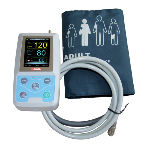
Gima ABPM User manual

Gima S.p.A. - Via Marconi, 1 - 20060 Gessate (MI) Italy
Italia: tel. 199 400 401 - fax 199 400 403
Export: tel. +39 02 953854209/221/225 fax +39 08 95380056
gima@gimaitaly.com - export@gimaitaly.com
www.gimaitaly.com
GIMA ABPM PULSE RATE MONITOR
WITH SpO2
User Manual
z
z
Contec Medical Systems Co., Ltd
No.24 Huanghe West Road,
Economic & Technical Development Zone,
Qinghuangdao, Hebei Province, 066004, P.R.C.
ATTENTION: The operators must carefully read and completely understand
the present manual before using the product
M-35111-EN-Rev.0.11.11
Shanghai International Trading Corp. GmbH (Hamburg)
Eiffestrasse 80, 20537, Hamburg, Germany
0123
PROFESSIONAL MEDICAL PRODUCTS

2

3
Chapter 1 INTRODUCTION................................................................. 5
1.1 General Information ............................................................ 7
1.2 Button Functions ................................................................ 8
1.3 Interfaces ............................................................................ 9
1.4 Accessories ........................................................................ 9
Chapter 2 GETTING STARTED ......................................................... 10
2.1 Open the Package and Check.......................................... 10
2.2 Dry Battery Installation...................................................... 10
2.3 Power On the Monitor....................................................... 10
2.4 Connect Oximeter Probe .................................................. 11
2.5 Connect NIBP Cuff ........................................................... 11
Chapter 3 FUNCTION INTERFACE................................................... 11
3.1 Main Inferface ................................................................... 11
3.2 System Menu.................................................................... 12
3.2.1 System Setup ................................................................... 13
3.2.2 BP SETUP......................................................................... 14
3.2.3 SpO2SETUP ..................................................................... 15
3.2.4 Patient Information ........................................................... 16
3.2.5 BP TABLE ......................................................................... 16
3.2.6 SpO2TABLE...................................................................... 17
3.2.7 DEMO Function ................................................................ 18
Chapter 4 SpO2MONITORING ......................................................... 19
4.1 What is the SpO2Monitoring ............................................ 19
4.2 Precautions during SpO2/Pulse Monitoring ...................... 20
4.3 Monitoring Procedure ....................................................... 20
4.4 Maintenance and Cleaning ............................................... 21
Chapter 5 NIBP MONITORING ......................................................... 21
5.1 Introduction....................................................................... 21
5.2 NIBP Monitoring ............................................................... 22
5.3 NIBP Message and Explanations ..................................... 24
5.4 Maintenance and Cleaning ............................................... 24
5.5 Transportation and Storage .............................................. 26
5.6 Key of Symbols................................................................. 26
Chapter 6 INSTALLATION OF THE SOFTWARE .............................. 26
6.1 Demand of Editor.............................................................. 26
INDEX
4
6.2 Installation of Software ..................................................... 27
Chapter 7 INTRODUCTION TO THE SOFTWARE ............................ 27
7.1 User register ..................................................................... 27
7.2 The main interface ............................................................ 29
7.3 Wear.................................................................................. 29
7.4 Design the measurement plan.......................................... 30
7.5 Data download.................................................................. 32
7.6 Choose patient data to edit .............................................. 32
7.7 Delete data le .................................................................. 33
7.8 Data le backup................................................................ 34
7.9 Edit Blood pressure data .................................................. 35
7.10 Trend Edit.......................................................................... 36
7.11 Display the statistics infomation....................................... 40
7.12 Edit of diagnose information............................................. 41
7.13 Sleep period change......................................................... 41
7.14 BP Thresholds .................................................................. 42
7.15 Histogram ......................................................................... 42
7.16 Piechart............................................................................. 43
7.17 Correlation line.................................................................. 43
7.18 Print report........................................................................ 44
7.19 Help .................................................................................. 46
Chapter 8 TROUBLESHOOTING GUIDE .......................................... 46
Appendix .......................................................................................... 45

5
Chapter1
INTRODUCTION
• Foranoverallintroductiontothemonitor,pleaserefertoGeneral
Information.
• Forbasicoperatinginstructions,pleaserefertoButtonFunction.
• Forallocationofinterfacesockets,pleaserefertoInterfaces.
Warning
Possible explosion hazard if used in the presence of ammable
anestheticsorotherammablesubstanceincombinationwithair,
oxygen-enrichedenvironments,ornitrousoxide.
Warning
Youmustverifyifthedeviceandaccessoriescanfunctionsafely
and normally before use.
Warning
Ensurethattheenvironmentinwhichthedeviceisoperatedisnot
subjecttoanysourcesofstrongelectromagneticinterference,such
asradiotransmitters,mobiletelephones,etc.KeepthemfarawayHigh
levelelectromagneticradiationemittedfromsuchdevicesmaygreatly
affect the monitor performance.
Warning
The disposal of scrap instrument and its accessories and packings
(includingbattery,plasticbags,foamsandpaperboxes)shouldfollow
the local laws and regulations.
Warning
Pleasechoosetheaccessoriesandprobewhichareapproved
ormanufacturedbythemanufacturer,orelseitmaydamagethedevice.
Warning
Disposeofthepackagingmaterial,observingtheapplicablewaste
control regulations and keeping it out of children’s reach.
Warning
The monitor is only for use on one patient at a time.
Warning
It is recommended that you check if there is any damage on the
monitorortheaccessoriesregularly,ifyoundanydamage,stop
usingit,andcontactthebiomedicalengineerofthehospitalorour
z
z
z
z
z
z
z
z

6
CustomerServiceimmediately.
Inaddition,theoverallcheckofmonitor,includingthesafetycheck
suchastheleakagecurrent,shouldbeperformedonlybyqualied
personnelonceevery12months.
Note
Please choose the computer which should be ensured compliance
withtherequirementsofIEC60950,orelseitmaydamagethedevice.
Note
ThesoftwarewasdevelopedperIEC60601-1-4.Thepossibility
of hazards arising from errors in the software program is minimized.
Caution
Attheendofitsservicelife,theproductdescribedinthismanual,
aswellasitsaccessories,mustbedisposedofincompliancewith
theguidelinesregulationthedisposalofsuchproducts.Ifyouhave
questionsconcerningdisposaloftheproduct,pleasecontactus
oritsrepresentatives.
z
z
z

7
1.1 General Information
Environment:
Temperature
Working 5~40(°C)
TransportandStorage -20~60(°C)
Humidity
Working ≤ 80 %
Transport and Storage ≤ 95 %
Altitude
Working -500to4,600m(-1,600to15,000ft)
TransportandStorage -500to13,100m(-1,600to43,000ft)
PowerSupply 3(V)DC
Pmax = 2.56VA
General instruction
Themonitornotonlymeasuretheambulatorybloodpressure,butalso
monitor the parameters of NIBP and SpO2. But it is applicable for adult only.
It integrates parameter measuring modules function and display function
inonedevice,featuringincompactness,lightweight.
The POWER switch is on the front panel. The RUN indicator and the ALARM
indicatorashonetimewhenthedeviceispoweredon.TheALARM
indicator ashes when alarm occurs. The sockets of the sensors are
at the top. USB is at the bottom of monitor.
Thismonitorisauser-friendlydevicewithoperationsconductedby
a few buttons on the front panel. Refer to Button Functions for details.
Measuring the ambulatory blood pressure function:
Inthismode,themonitorcanwork24hourscontinuously.Themonitor
havethecapableofrecordingupto4800measurements,thestoredreadings
in the monitor are downloaded into the computer to proceed the function
includingeditingthedata,editingthetrendgraph,statistic,displaying
theinformation,editingthediagnosticinformation,settingtheparameters
andprintingandsoon.However,thismonitorcannottransmitdata
real-time in the process of measuring.
Monitoring function:
NIBP
- Fromlefttoright,thereareSystolicpressure,Meanpressure
andDiastolicpressure(unit:mmHgorkPa)
SpO2
- SpO2(unit:%)
- PulseRate(unit:beats/minute)(When“BOTH”itemisselected)
Note
Inthismode,thelengthofworkingtimecontinuouslyisdecidedbythe
intervalofmeasurementsetbytheuser.
z

8
It is useful that the software at the state of monitoring as the ambulatory
blood pressure.
Refer to Software Functions for details.
1.2 Button Functions
All the operations to the monitor are through the buttons at the bottom
ofthepanel.Thenamesofthebuttonsareabovethem.Theyare:
POWER
Press the button and the system will start.
Note
Whenthebatteryislow,thealarmoccurs.
MENU
Whateverlevelsofmenuthesystemisin,pressthebuttonand
the system immediately executes a certain function.
UP
Press the button to select the menu item and modify the setup.
DOWN
Press the button to select the menu item and modify the setup.
In the main interface press this button less than 1second to enter alarm
pausestatus.Press“DOWN”for1secondtoenterthesilencestatus
and a symbol appears at main screen. When the system
isinsilencestatus,anynewlygeneratedalarmwilldischarge
thesilencestatusandmakethesystemgivenormalalarmstatus.
Note
PulsetonewillbeheardinSilencestatus,IfnewalarmoccursinAlarm
Silencestatus,thesystemwilldischargeSilencestatusautomatically,
or the silence status will be discharged automatically 1 minute later.
NIBP
Press to inate the cuff to start a blood pressure measurement. When
measuring,presstocancelthemeasurementanddeatethecuff.
Method to use the button to operate in the screen:
TherectangularmarkinthescreenthatmoveswiththeUPbuttonorDOWN
buttoniscalled“cursor”.Operationcanbeperformedatanyposition
at which the cursor can stay.
Whentheitemisnottoselect,thecursoriswhite;whenpressMENU
toselecttheitem,thecursorbecomered.
z
z
OK

9
1.3 Interfaces
Fortheconvenienceofoperation,thedifferentkindsofinterfaces
are in different parts of the monitor.
At the top is the Socket for SpO2Sensor and socket for NIBP cuff
1the Socket for NIBP cuff
2the Socket for SpO2Sensor
AtthebottomisthesocketforUSB,asshowninFigure1.3.2.
①the Socket for USB
1.4 Accessories
A a cuff for adult
B a usb data line
C a oximeter probe (Model: SpO2-01-DR)
Dadisk(PCsoftware)
E a pouch
F a user manual
Warning
Please use the accessories supplied by the manufacturer or replace
theaccessoriesaccordingtotherequirementsofthemanufacturer
inordertoavoidmakingharmstopatients.
z
Figure 1.3.1
Top
Figure 1.3.2
Bottom
1
2
1

10
Chapter 2
GETTING STARTED
• Openthepackageandcheck
• Drybatteryinstallation
• Poweronthemonitor
• Connectpatientsensors
2.1 Open the Package and Check
Open the package and take out the monitor and accessories carefully.
Keep the package for possible future transportation or storage.
Check the components according to the packing list.
• Checkforanymechanicaldamage.
• Checkallthecables,modulesandaccessories.
Ifthereisanyproblem,contactthedistributorimmediately.
2.2 Dry battery installation
The monitor will be supplied with two ‘AA’ alkaline batteries or high capacity.
Before using the monitor you shall put the battery in the box of battery.
Note
Whenyoudon’tusethemonitor,youwilltakeoutthedrybattery.
2.3 Power on the monitor
PressPOWERtopoweronthemonitor.Theindicatorwillash,thesystem
willentermonitoringscreenofmonitoringorABPM,andyoucanperform
normal monitoring now. Refer to System Menu for details.
Warning
Ifanysignofdamageisdetected,orthemonitordisplayssomeerror
messages,donotuseitonanypatient.Contactbiomedicalengineer
inthehospitalorourCustomerServiceCenterimmediately.
Note
Check all the functions that may be used to monitor and make sure that
the monitor is in good status.
z
z
z

11
2.4 Connect Oximeter Probe
Note
Forinformationoncorrectconnection,refertoFigure2.4
2.5 Connect NIBP Cuff
Connect NIBP extension conduit between the monitor and the patient.
Note
Forinformationoncorrectconnection,refertoFigure2.5.
Chapter3
FUNCTION INTERFACE
• MainInterface
• SystemMenu
3.1 Main Interface
PressPOWERtopoweronthemonitor,Theindicatorwillash,thesystem
will enter the main interface successfully.
ABPM : If there is no key-press operation within the time set in the
BACKLIGHTTIMEitem,themonitorwillenterstandbymode.
RUNindicatorlightashesonceeveryother2seconds,indicating
the monitor is under working mode.
Monitoring Mode: BACKLIGHT TIME item setup is of no effect. The backlight
is bright all the time.
The ‘04’ will be displayed in the middle of the speaker and battery when
the power is low.
z
Figure 2.4
THE SpO2PROBE
z
Figure 2.5
THE CUFF

12
The main interface is shown as the follow:
Note
Whentheregisterisfull,willbeappearanceatthetopofscreen.
Thenoteofthelastvalueneedstobecleared.
3.2 System Menu
Press the MENU button on the panel to call up the [SYSTEM MENU].
You can perform option operations by using UP and DOWN buttons.
Figure 3.1.1
ABPM main menu
z
Figure 3.1.2
Monitoring main menu

13
[PMBPSETUP],[PMSpO2SETUP] and [SpO2TABLE] are gray in the mode
of ABPM. They cannot be set up.
3.2.1 System Setup
Select the SYSTEM SETUP item in the [SYSTEM MENU].
The following menu will pop up.
Users can set up the system time by selecting the [TIME] item.
Ifusersselect[YES]inthe[DEFAULT]item,themonitorwillcomeback
to factory default.
Inthe[LANGUAGE]item,userscanselectthewordsshowninChinese
or English in the screen.
Figure 3.2
System menu
z
Figure 3.2.1
System setup

14
Ifusersselect[ON]inthe[ALARM]item,theloudspeakerturnson.
willbeappearedinthemainmonitoringinterface.Ontheotherhand,
whenusersselect[OFF],theloudspeakerturnsoff,
will turns up.
Inthe[NEWPATIENT]item,ifusersselect[OFF],the“Clearthelastvalue?
“dialogboxwillappear.
Select[YES]againwilldeletethemeasurerecordofthelastpatient,then
select[NO]backtothe[SYSTEMSETUPMENU].Else,selecting[NO]
atrst,themonitorwilldonothing.Pleasepayattentiontothisfunction.
Users can select PM or ABPM in the [FUNCTION SELECT] item
and correspond measures will be taken.
Inthe[BACKLIGHTTIME]item,userscanmakeitfrom5to120seconds
with 5 seconds per step. Its function is to control the backlight time
of the main interface in ABPM.
UndertheABPM,[DEFAULT],[ALARM]and[NEWPATIENT]cannot
be set up.
3.2.2 BP SETUP
Select[PMBPSETUP]inthe[“SYSTEMMENU”].Thefollowingmenuwill
pop up.
Whenusersselect[ON]inthe[AUTOMEASURE]item,theMonitorwillme-
asure blood pressure according to the time selected in the [INTERVAL] item.
When[OFF]isselected,manualmeasureisneeded,simultaneously[INTER-
VAL] item turns gray and cannot be set up.
Theintervaltime(Unit:minute)setupinthe[INTERVAL]itemcanbeselected
fromthefollowingoptions:5,10,15,20,30,45,60,90.
Figure 3.2.2
BP setup

15
Thealarmisonoroffaccordingtothehighandlowlimitswhichhavebeen
set up. When the pressure higher than the high limit or lower than the low
limit,thealarmwilloccur.[SYSALM],[MEANALM]and[DIAALM]canbe
processed separately.
The adjustable ranges of the high and low limits of the alarm are as follows:
DIA ALM: 40~270 mmHg
SYS ALM: 10~215 mmHg
MEAN ALM: 20~235 mmHg
3.2.3 SpO2SETUP
Select [PM SpO2SETUP]inthe“SYSTEMMENU”.
The following menu will pop up.
Forthe[PULSESOUND]item,youcanchooseitsstate.Whenitis“ON”,
pulse sound plays while the monitor measure the ambulatory blood pressure.
Whenitis“OFF”,pulsesounddosen’tplaywhilethemonitormeasurethe
ambulatory blood pressure.
For the [SpO2ALMHI/LO]item,youcansetup[SpO2ALM H] and [SpO2ALM
LO].Alarmoccurs,whenSpO2valueoverows.
Forthe[PRALMHI/LO]item,youcansetup[PRALMHI]and[SpO2ALM
LO].Alarmoccurs,whenPRvalueoverows.
SpO2and PR ALARM analysis alarm limits:
Figure 3.2.3
SpO2setup
PARAMETERS Max. HI Min. LO Step
SpO2100 0 1
PR 254 0 1

16
3.2.4 Patient Information
Pickthe[ABPMINF0]iteminthe“SYSTEMMENU”tocallupthefollowing
menu.
Theinformationinthisinterfacecan’tbechanged,untilreinstall
the parameter in software.
3.2.5 BP TABLE
Pickthe[BPTABLE]iteminthe“SYSTEMMENU”tocallupthefollowing
menu.
[total]:thenumberisthetotalofalldatahavebeenmeasuredfromaccessing
thisinterfacethersttime.Thesequencenumberofthecurrentrstlinewill
Figure 3.2.4
ABPM infor
Figure 3.2.5.1
NIBP table

17
bedisplayedwhenchangingthedataorturningoverpages.Everypagecan
contain 10 data at most.
Select the [change] item to enter the [Change The Number] menu:
Whenthenumberwhichyouinputismorethanthetotal,itwillprompt“>
total”.Bloodpressuremeasureonetimeper5minutes,andthemostnumber
of times is 4896.
3.2.6 SpO2TABLE
Pick the [SpO2TABLE]iteminthe“SYSTEMMENU”tocallupthefollowing
menu.
Figure 3.2.5.2
Change
Figure 3.2.6.1
SpO2table

18
[total]:thenumberisthetotalofalldatahavebeenmeasured,while
accessingthisinterfaceforthersttime.Thesequencenumberoftherst
linecurrentlywillbedisplayed,whilechangingthedataorturningoverpage.
Everypagecancontain10dataatmost.
Select the [change] item to enter the [Change The Number] menu:
Whenthenumberwhichyouinputismorethanthetotal,itwillprompt
“>total”.Thebloodpressureismeasuredonceper1s,andthemostnumber
of times is 183000.
3.2.7 DEMO function
Selectthe[DEMO]itemtoenterDEMOstatus.IntheDEMOstatus,pressthe
“MENUKEY”,andsystemreturnstothe“MAINMENU”.
Figure 3.2.6.2
Change
Figure 3.2.7
Demo

19
Note
Inclinicalapplication,thisfunctionisforbiddenbecausetheDEMO
willmisleadthemedicalstafftotreattheDEMOwaveformand
parameterastheactualdataofthepatient,whichmayresult
in the delay of treatment or mistreatment.
Whenitisambulatorybloodpressurestate,[PMBPSETUP]、[PMSpO2
SETUP]and[TABLE]can’tbechangedinthe“MAINMENU”.
Chapter 4
SpO2MONITORING
4.1 What is the SpO2 Monitoring
SpO2Plethysmogram measurement is employed to determine the oxygen
saturationofhemoglobininthearterialblood.If,forexample,97%
hemoglobin molecules in the red blood cells of the arterial blood combine
withoxygen,thenthebloodhasaSpO2oxygen saturation of 97%.
The SpO2numeric on the monitor will read 97%. The SpO2numeric shows
thepercentageofhemoglobinmoleculeswhichhavecombinedwithoxygen
molecules to form oxyhemoglobin. The SpO2/PLETH parameter can also
provideapulseratesignalandaplethysmogramwave.
How the SpO2/ PLETH Parameter Works
• Arterialoxygensaturationismeasuredbyamethodcalledpulseoximeter.
Itisacontinuous,non-invasivemethodbasedonthedifferentabsorption
spectra of reduced hemoglobin and oxyhemoglobin. It measures how
muchlight,sentfromlightsourcesononesideofthesensor,is
transmittedthroughpatienttissue(suchasangeroranear),toareceiver
on the other side.
Thesensormeasurementwavelengthsarenominally660nmforthe
Red LED and 940nm for Infrared LED. Maximum optical power output
for LED is 4 mW.
• Theamountoflighttransmitteddependsonmanyfactors,mostofwhich
areconstant.However,oneofthesefactors,thebloodowinthearteries,
varieswithtime,becauseitispulsating.Bymeasuringthelightabsorption
duringapulsation,itispossibletoderivetheoxygensaturation
ofthearterialblood.DetectingthepulsationgivesaPLETHwaveform
and pulse rate signal.
• TheSpO2valueandthePLETHwaveformcanbedisplayedinthemain
screen.
z

20
Warning
ES(Electrosurgery)equipmentwireandSpO2cable must not be
tangled up.
Warning
Donotputthesensoronextremitieswitharterialcatheterorvenous
syringe.
Note
Do not perform SpO2measuring and NIBP measuring on same arm
atonetime,becauseobstructionofbloodowduringNIBPmeasuring
mayadverselyaffectthereadingofSpO2value.
4.2 Precautions during SpO2/Pulse Monitoring
Note
、Makesurethenailcoversthelightwindow;
① The wire should be on the backside of the hand.
Note
SpO2waveformisnotproportionaltothepulsevolume.
Warning
Do not use the SpO2sensor once the package or the sensor is found
damaged.Instead,youshallreturnittothevendor.
Warning
Prolonged and continuous monitoring may increase jeopardy
ofunexpectedchangeofdermalconditionsuchasabnormalsensitivity,
rubescence,vesicle,repressiveputrescence,andsoon.Itisespecially
important to check the sensor placement of neonate and patient of poor
perfusion or immature dermogram by light collimation and proper
attaching strictly according to changes of the skin. Check per 2~3 hours
thesensorplacementandmoveitwhentheskindeteriorates.
Morefrequentexaminationsmayberequiredfordifferentpatients.
4.3 Monitoring Procedure
SpO2plethysmogram measurement
1. Switch on the monitor.
2. Attach the sensor to the appropriate site of the patient nger.
3. Plug the connector of the sensor extension cable into the SpO2socket,
please pay attention to the direction of the sensor.
4.PleasepulloutthesensorWhenmeasureisover.
z
z
z
z
z
z
z
Other manuals for ABPM
1
Table of contents
Other Gima Blood Pressure Monitor manuals