Gima ABPM User manual

GIMA ABPM PULSE RATE MONITOR
z
z
Contec Medical Systems Co., Ltd
No.24 Huanghe West Road,
Economic & Technical Development Zone,
Qinghuangdao, Hebei Province, 066004, P.R.C.
M-35110-EN-Rev.0.10.11
Shanghai International Trading Corp. GmbH (Hamburg)
Eiffestrasse 80, 20537, Hamburg, Germany
0123
PROFESSIONAL MEDICAL PRODUCTS
Gima S.p.A. - Via Marconi, 1 - 20060 Gessate (MI) Italy
Italia: tel. 199 400 401 - fax 199 400 403
Export: tel. +39 02 953854209/221/225 fax +39 08 95380056
gima@gimaitaly.com - export@gimaitaly.com
www.gimaitaly.com
User Manual
ATTENTION: The operators must carefully read and completely understand
the present manual before using the product

2

3
Chapter 1 INTRODUCTION................................................................. 5
1.1 General Information ............................................................ 6
1.2 Button Functions ................................................................ 8
1.3 Interfaces ............................................................................ 8
1.4 Accessories ........................................................................ 9
Chapter 2 GETTING STARTED ......................................................... 10
2.1 Open the Package and Check.......................................... 10
2.2 Dry battery installation...................................................... 10
2.3 Power on the instrument................................................... 10
2.4 Connect Sensor................................................................ 11
Chapter 3 Function Interface............................................................ 11
3.1 Main Interface ................................................................... 11
3.2 Measuring Interface .......................................................... 12
3.3 Measure Result Interface.................................................. 13
3.4 System Menu.................................................................... 14
3.4.1 System Setup ................................................................... 14
3.4.2 System Time ..................................................................... 16
3.4.3 Data Delete ....................................................................... 16
3.4.4 Alarm Setup ...................................................................... 17
3.4.5 ABPM Menu...................................................................... 18
3.4.6 ABPM Data Review........................................................... 19
3.4.7 Ordinary User Data Review............................................... 20
3.5 ABPM Working Interface................................................... 22
Chapter 4 NIBP Measuring ............................................................... 23
4.1 Introduction....................................................................... 23
4.2 NIBP Measuring................................................................ 23
4.3 Operation Hints................................................................. 25
4.4 NIBP Error Message and Explanations............................. 27
4.5 Maintenance and Cleaning ............................................... 27
4.6 Transportation and Storage .............................................. 28
4.7 Key And Symbols ............................................................. 29
Chapter 5 Installation of the Software.............................................. 29
5.1 Demand of editor.............................................................. 29
5.2 Installation of software...................................................... 29
INDEX

4
Chapter 6 INTRODUCTION TO THE SOFTWARE ............................ 30
6.1 The main interface ............................................................ 30
6.2 Patient File Path................................................................ 31
6.3 Wear.................................................................................. 31
6.4 Data download.................................................................. 32
6.4.1 Data download via USB.................................................... 32
6.5 Choose patient data to edit .............................................. 32
6.6 Delete data le.................................................................. 33
6.7 Data le backup................................................................ 34
6.8 Edit Blood Pressure data .................................................. 35
6.9 Trend Edit.......................................................................... 36
6.10 Histogram ......................................................................... 36
6.11 Pie chart............................................................................ 37
6.12 Print Report....................................................................... 37
6.13 Send Cases To Net Server................................................ 38
Chapter 7 TROUBLESHOOTING GUIDE .......................................... 39

5
CHAPTER 1
INTRODUCTION
For an overall introduction to the Blood Pressure Monitor, please
refer to General Information.
For basic operating instructions, please refer to Button Function.
For allocation of interface sockets, please refer to Interfaces.
Warning
Possible explosion hazard if used in the presence of ammable
anesthetics or other ammable substance in combination with air,
oxygen-enriched environments, or nitrous oxide.
Warning
You must verify if the device and accessories can work safely
and normally before using.
Warning
Ensure that the environment in which the device is operated is not
subject to any sources of strong electromagnetic interference, such
as radio transmitters, mobile telephones, etc. Keep them far away high
level electromagnetic radiation emitted from such devices may greatly
affect the instrument performance.
Warning
Dispose of the packaging material, observing the applicable waste
control regulations and keeping it out of children’s reach.
Warning
Please choose the accessories which are approved or manufactured
by the manufacturer, or else it may damage the device.
Warning
The monitor is only for use on one patient at a time.
Warning
When the monitor is wetted, please stop using it and contact us.
Warning
If Luer lock connectors are used in the construction of tubing,
there is a possibility that they might be inadvertently connected
to intravascular uid systems, allowing air to be pumped into
a blood vessel.
z
z
z
z
z
z
z
z

6
Warning
When used with Electro-surgery equipment, you must give top priority
to the patient safety.
Warning
It is recommended that you check if there is any damage on the monitor
or the accessories regularly, if you nd any damage, stop using it,
and contact the biomedical engineer of the hospital or our Customer
Service immediately. In addition, the overall check of monitor, including
the safety check such as the leakage current, should be only performed
by qualied personnel once every 12 months.
Note
Please choose the computer which should be ensured compliance
with the requirements of IEC 60950, or else it may damage the device.
Note
The software was developed per IEC60601-1-4. The possibility
of hazards arising from errors in the software program is minimized.
Note
The monitor shall comply with the standard EN1060 series:
Part 1: General requirements;
Part 3: Supplementary requirements for electro-mechanical blood
pressure measuring systems (in course of preparation).
Caution
At the end of its service life, the product described in this manual,
as well as its accessories, must be disposed of in compliance with
the guidelines regulation the disposal of such products. If you have
questions concerning disposal of the product, please contact us
or its representatives.
1.1 General Information
Environment:
Temperature
Working 5~40 (˚C)
Transport and Storage -20~55 (˚C)
Humidity
Working 15%~80%
Transport and Storage ≤ 95 %
Altitude 80kPa~105kPa
Power Supply 3 (V) DC
P ≤2.4VA
z
z
z
z
z
z

7
PAVIMENTO
Safety:
This device is debrillator protected. Note that no precautions
specic to the device is required during debrillation, and debrillation
discharge has no effect on the monitor. The equipment uses
the gray silicone airway, in case of the effect to the equipment
when debrillation device was used on the patient.
General instruction
The device is applied to Blood Pressure(BP) measure and monitor
for adult,pediatric, and neonatal. It most stores 300 records of common
user and 358 of ambulatory Blood Pressure data. Every record includes
the detailed measure time, systolic blood pressure, diastolic blood pressure,
mean blood pressure, pulse rate, error message and record number, etc.
This device has friendly operation interface, and adopts 2.4inch color LCD.
It integrates data review function and display function which includes
large-print single record data review, data list, BP data trends chart,
the current time, data, power, alarm and so on.
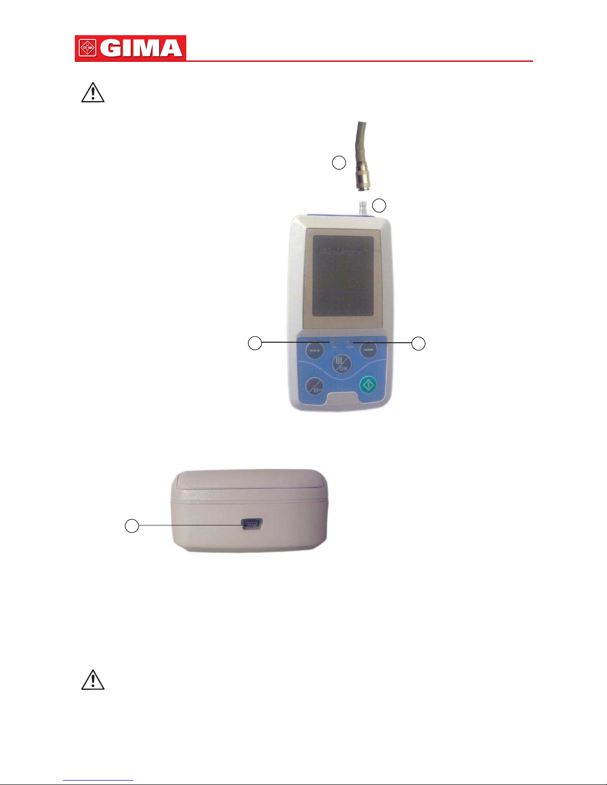
User can power on/off the monitor, start manual measure, set system
parameters and so on with ve keys in the front panel. (Please refer to
“Button Functions” part for detail).
There are sound and light alarm functions that the buzzer intermittently
beeping and the red light ashing to prompt low power. When the measure
result exceed the alarm limit, the color of the measure results style becomes
red and aroses sound alarm. The user can turn on or off the alarm sound
if necessary.
The cuff socket is located on the top of the device and the USB socket
at the bottom of the device. The stored data can be transferred to computer
with the USB interface, and then various operations can be performed
by using the PC software. (Please refer to “Software Functions” part
for detailed contents).
Note
If there is no operation in the common user mode, the device will turn
off backlight according to the “BACKLIGHT TIME” you set, and if
no action for three minutes, the device will automatically turn off.
When the backlight turn off in the Ambulatory Blood Pressure mode,
the green indicator intermittently ashes to prompt the device
in running state.
OK
z

8
1.2 Button Functions
All the operations of the Blood Pressure Monitor could be completed
with the buttons. The names of button are on them. They are:
Press the button for a long time, then the system will start. When
turning on and off the monitor, the red light and the green both ash
once to prompt that the on or off operation is successful. Press it for
a short time to return the boot-strap interface.
The text in the middle bottom of the screen indicate the function
of this key. Whatever menus the system is in, press the button
and the system immediately executes a certain function.
The text in the left bottom of the screen indicate the function of this
key.
Such as: The button is the alarm switch in the boot-strap interface,
up key in the “System Menu”, and left key in the “trend “chart.
The text in the right bottom of the screen indicate the function of this
key.
Such as: the button is the data review key of current user in the
boot-strap interface and down key in the “System Menu” and right
key in the “trend” chart.
Start/Stop button. If measuring, press this key to cancel the current
measurement
Note
During uploading data with the USB, the backlight must be in awake
state, and as far as possible reduce operation, and cannot carry on
BP measuring operation.
Note
During measurement, three buttons are all disabled.
The rectangular mark in the screen moving with the operation of ,
buttons is called “cursor”. Operation can be performed in any
position at which the cursor can stay. When the item is not selected,
the cursor is yellow; when selected, the cursor becomes red.
1.3 Interfaces
For the convenience of operation, different kinds of interfaces are in different
parts of the instrument. NIBP cuff socket is at the top.
OK
OK
OK
OK
OK
z
z
OK
OK
OK
OK
OK

9
Note
Cuff is connected to the monitor through the extended gas pipe.
1Port of extended gas pipe
2The socket for Gas pipe
3Run indicator
4Alarm indicator
At the bottom is the socket for USB
1 the Socket for USB, connect the data line to upload data
1.4 Accessories
A cuff for adult
B a USB data line
C a disk (PC software)
D a user manual
E a pouch
Warning
Please use the special accessories supplied by the manufacturer
or replace the accessories according to the requirements
of the manufacturer in order to avoid making harms to patients.
1
2
4
3
Figure 1.3.1
The top external airway
Figure 1.3.2
Bottom
1
z
z

10
Chapter 2
GETTING STARTED
• Open the package and check
• Dry battery installation
• Power on the instrument
• Connect patient sensors
2.1 Open the Package and Check
Open the package and take out the equipment and accessories carefully.
Keep the package material for possible future transportation or storage.
Check the components according to the packing list.
• Check for any mechanical damage.
• Check all the cables, modules and accessories.
If there is any problem, contact the distributor immediately.
2.2 Dry battery installation
The instrument will be supplied with two ‘AA’ alkaline batteries or high
capacity. Before using the instrument, you shall put the battery in the battery
box in the back of the monitor.
Note
When you don’t use the equipment, you should take out the dry
battery.
2.3 Accensione apparecchio
Press button to power on the instrument. The indicators will ash once,
which shows the boot-strap is success, then end pressing, the system will
enter into the main interface.
Warning
If any sign of damage is detected, or the instrument displays some
error messages, do not use it on any patient. Contact biomedical
engineer in the hospital or our Customer Service Center immediately.
Note
Check all the functions that possibly be used and make sure that the
equipment is in good status.
OK
z
z
z

11
2.4 Connect Sensor
Note
For information on correct connection of NIBP cuff,
refer to Figure 2.4.
Connect the sensor between the monitor and the measure part of the patient.
Chapter 3
FUNCTION INTERFACE
• Interfaccia principale
• Menu sistema
3.1 Main Interface
Press to power on the instrument. The indicator will circularly ash
once, which show the boot-strap is success, then end pressing, the system
will enter into the main interface.
In common user mode, if there is no key-press operation during the time
which system sets, the device will turn off LCD and enter into standby
mode, if there is no any operation in the standby mode, the device
will automatically turn off; the “RUN” indicator ashes once every 2 seconds
to prompt the device in working state.
When the power is low, the battery progress bar is empty, at the same
time the alarm sound occurs, and the red indicator ashes in xed time.
In the Main Interface:
Alarm-switch status is displayed in the left top of the screen, button
can switch the alarm status shortly.
User bar displays the current patient type (adult, pediatric, neonatal),
and the amount of the common user’s data record.
Current date and time is displayed in the middle top of the screen,
the precision of the time is second.
z
Figura 2.4
Connection method
CUFF
OK
OK

12
The boot-strap interface is shown as the follow
Note
All interfaces except the trend retain power icon, alarm switch, as well
as a small font of the current time.
Note
After the register overow, the rst record will be overwritten, “Over-
ow” message is shown in the boot-strap interface. The interface is
shown as the follow:
3.2 Measuring Interface
Measuring interface displays real-time cuff pressure and the current
measurement information. In the measurement process, except the
and the buttons, other buttons are disabled.
Figure 3.1.1
Common user boot-strap
interface 1
Figura 3.1.2
Common user boot-strap
interface 2
z
z
OK
OK

13
The measuring interface is shown as the follow:
Note
In any interface except the measurement, press key to exit
current interface and back to the boot-strap interface.
3.3 Measure Result Interface
The measure result includes:
SYS: systolic blood pressure (mmHg/kPa)
DIA: diastolic blood pressure (mmHg/kPa)
PR: pulse rate (bpm)
OK
Figura 3.3.1
Measure results interface 1
z
Figura 3.2
Measuring interface

14
If there is an error during the measurement, an error message text will appear
on the screen.
3.4 System Menu
In the boot-strap interface, according to the text in the middle bottom
of the screen, press button, then enter the system menu and execute
different option operations by using keys.
3.4.1 System setup
Enter “SYSTEM SETUP” item in the [SYSTEM MENU], the following menu
will pop up:
Figura 3.4.1
System menu
Figura 3.3.2
Measure result interface 2
OK
OK
OK

15
“SYSTEM SETUP” menu includes:
“Language” item has two choices: Chinese, English;
“Unit” item has two choice: mmHg, kPa;
“User Purview” item cannot be operated: all;
“Measure Mode” item has three options: adult, pediatric, neonatal,
“Backlight Time(s)”item has four choices: 15, 30, 60, 120.
Note
“Backlight Time” in the “System Settings” is used by the common
user, backlight time in ambulatory blood pressure monitor (ABPM)
is a xed value of 5S.
Select “ABPM Setup” item in [System Setup] menu, the following menu
will pop up:
Figura 3.4.2
System setup
Figura 3.4.3
ABPM Setup
z

16
“Awake measurement time interval”(min/h) could be options: 15, 30, 60, 120;
“Asleep measurement interval”(min/h) could be options: 15, 30, 60, 120, 240;
“Awake time” And “Asleep time” transformation unit are 30 minutes.
3.4.2 System Time
Select “System Time” item in [System Menu], the following menu will pop up:
Select “Conrm” after time setup complete, time change is successful
and exit system time setup and return the previous menu.
Select “Exit” to cancel the setting and return to the previous menu.
3.4.3 Data Delete
Select “Yes” in “Data Delete” menu
of [SYSTEM MENU], after you press
certain key, the following menu
will pop up:
If press “OK”, the common user data will be daleted, if press “return”,
the operation will be cancelled.
Figura 3.4.4
System time
Figura 3.4.5
Data delete

17
3.4.4 Alarm Setup
Select “Alarm Setup” item in [System Menu], the following menu will pop up:
“Alarm switch” can control closing or unsealing of the sound alarm;
The alarm is on or off according to the high and low limits which have been
set up. When the pressure is higher than the high limit or lower than the low
limit, the alarm will occur.
The adjustable ranges of the high and low limits of the adult mode alarm
are as follows:
SYS ALM: 40~270 mmHg - DIA ALM: 10~215 mmHg
The adjustable ranges of the high and low limits of the pediatric mode alarm
are as follows:
SYS ALM: 40~200 mmHg - DIA ALM: 10~150 mmHg
The adjustable ranges of the high and low limits of the neonatal mode alarm
are as follows:
SYS ALM: 40~135 mmHg - DIA ALM: 10~100 mmHg
“Default” includes the main content:
Default data: 2009-10-25;
Time: 10:15;
Measure mode: adult;
Alarm parameter:
Alarm switch: close;
Measure unit: mmHg;
Figura 3.4.6
Alarm setup
Use
mode
Adult
Pediatric
Neonatal
High pressure
high limit
140
120
100
High pressure
low limit
90
70
60
Low pressure
high limit
90
70
60
Low pressure
low limit
40
40
20

18
Language: Chinese;
Ordinary user backlight time: 10s;
ABPM switch: close;
Asleep time: 22:00;
Asleep measurement interval: 15minutes;
Awake measurement interval: 30minutes;
Awake time: 7:00;
Alarm switch: close.
3.4.5 ABPM Menu
Select “ABPM” menu in [System Menu], the following menu will pop up.
In “ABPM” menu, “ABPM ON-OFF” select “open”, then prompt message
of ABPM of the current user, such as:
Figura 3.4.7
ABPM
Figura 3.4.8
ABPM prompt menu

19
OK
OK
OK
Figura 3.4.9
ABPM “large-print”
OK
Figura 3.4.10
ABPM “Table”
Press button, clear the ambulatory blood pressure measure data,
and enter ambulatory Blood Pressure Mode;
Press button, save ambulatory Blood Pressure measure data,
and enter ambulatory Blood Pressure Mode;
Press button, give up the choice, and return the previous menu.
3.4.6 ABPM Data Review
3.4.6.1 ABPM “large-print” Data Review
Select “ABPM Data” item in “ABPM” menu, the following interface
will pop up.
Every record is an interface, and display content include: the current user,
total of the current user record data, serial number of the record, stored time
of the record, high pressure, low pressure, mean pressure, Pulse Rate.
3.4.6.2 ABPM Data “Table”
Press button to select “trend”
in ABPM large-print data review menu,
the following interface will pop up

20
A interface contain 5 records, every record includes time, high pressure,
low pressure, mean pressure, Pulse Rate.
3.4.6.3 ABPM Trend
Press button to select “trend”, in ABPM large-print data review menu,
the following interface will pop up:
Trend interface can trace 100 record trends, if measuring data are more than
100 items, press , buttons can glide trend curve for left and right,
the scale of the vertical axis and the starting point, end point automatically
adjust according to the width of the stored data. The displayed dates that
are at the bottom of trends shown the trend for the rst point and last
point of data recording time.
3.4.7 Ordinary User Data Review
3.4.7.1 Ordinary User “large-print”
Data Review
Press button enter the ordinary user
“large-print” data review in boot-strap interface,
the following interface will pop up:
Figura 3.4.11
ABPM “trend”
OK
OK
OK
OK
Figura 3.4.12
Ordinary user “large-print”
Other manuals for ABPM
1
Table of contents
Other Gima Blood Pressure Monitor manuals