manuals.online logo
Brands
  1. Home
  2. •
  3. Brands
  4. •
  5. Heat & Glo
  6. •
  7. Fireplace Accessories
  8. •
  9. Heat & Glo OGL-42 Manual

Heat & Glo OGL-42 Manual

01/04 4036-903 Rev C 1
INSTALLATION & OPERATING
INSTRUCTIONS
OGL-42-NG, OGL-42-LP
OUTDOOR GAS LOG SET
WARNINGS!
 For outdoor use only!
 This appliance is tested and listed for use only with the optional accessories listed in these instructions. Use of optional
accessories not specifically tested for this appliance could void the warranty and/or result in a safety hazard.
 Improper installation, adjustment, alteration, service or maintenance can cause injury or property dama e. Refer to this
manual. For assistance or additional information, consult a qualified installer, service a ency or the as supplier.
WARNING: If the information in this manual
is not followed exactly, a fire or explosion may
result causing property damage, personal in-
ury or loss of life.
 Do not store or use gasoline or other
flammable vapors and liquids in the vicinity of
this or any other appliance.
 What to do if you smell gas
 Do not try to light any appliance.
 Do not touch any electrical switch; do not
use any phone in your building.
 Immediately call your gas supplier from a
neighbors phone. ollow the gas suppliers
instructions.
 If you cannot reach your gas supplier, call
the fire department.
 Installation and service must be performed by
a qualified installer, service agency or the gas
supplier.
Æ
2 4036-903 Rev C 01/04
OGL-42 INSTALLATION INSTRUCTIONS
Safety Precautions
1. Please read these installation instructions completely before beginning installation procedures. Failure to follow them could
cause an appliance malfunction resulting in serious injury and/or property damage.
2. Always check your local building codes prior to installation. The appliance installation must comply with all local, regional, state and
national codes and regulations.
3. NEVER leave children unattended when there is a fire burning in the appliance.
4. This gas appliance is not built for solid fuel. NEVER use gasoline, gasoline type lantern fuel, kerosene, charcoal lighter fluid, or
similar li uids in this appliance. Keep any flammable li uids a safe distance from the appliance.
5. DO NOT use chimney cleaners or flame colorants in your appliance.
6. While servicing this appliance, always shut off any electricity or gas to the appliance. This will prevent possible electric shock or
burns. Also, make sure the appliance is completely cooled before servicing.
7. To avoid the risk of damaging appliance materials and increasing the risk of spreading a fire, do not use the appliance to cook or
warm food.
WARNING!
This appliance and its components are desi ned to be installed and operated as a system. Any alteration to or substitution
for items in this system, unless allowed by these installation instructions, will void the Underwriters Laboratories listin
and may void the product warranty. It may also create a hazardous installation. Read throu h these instructions thorou hly
before startin your installation and follow them carefully throu hout your project.
A. LISTINGS AND CODE APPROVALS
This appliance has been tested and listed in accordance with CSA
4-96 U.S. (2nd edition), Outdoor Gas Fireplaces and UL127,
Factory-Built Fireplaces standards, and has been listed by
Underwriters Laboratories Inc. for installation and operation in the
United States and Canada as described in this manual.
Check with your local building code agency prior to installing this
appliance to ensure compliance with local codes, including the
need for permits and follow-up inspections. In the absence of local
codes, comply with the Natural Fuel Gas Code, ANSI Z223.1-
Latest Edition in the United States and CAN/CGA B149
Installation Codes in Canada.
If you need assistance during installation, please contact your local
dealer or the Heat-N-Glo Technical Services Department,
Hearth&Home Technologies Inc. at 1-888-427-3973.
Table of Contents
A. Listings and Code Approvals ......................................................................................................................................... 2
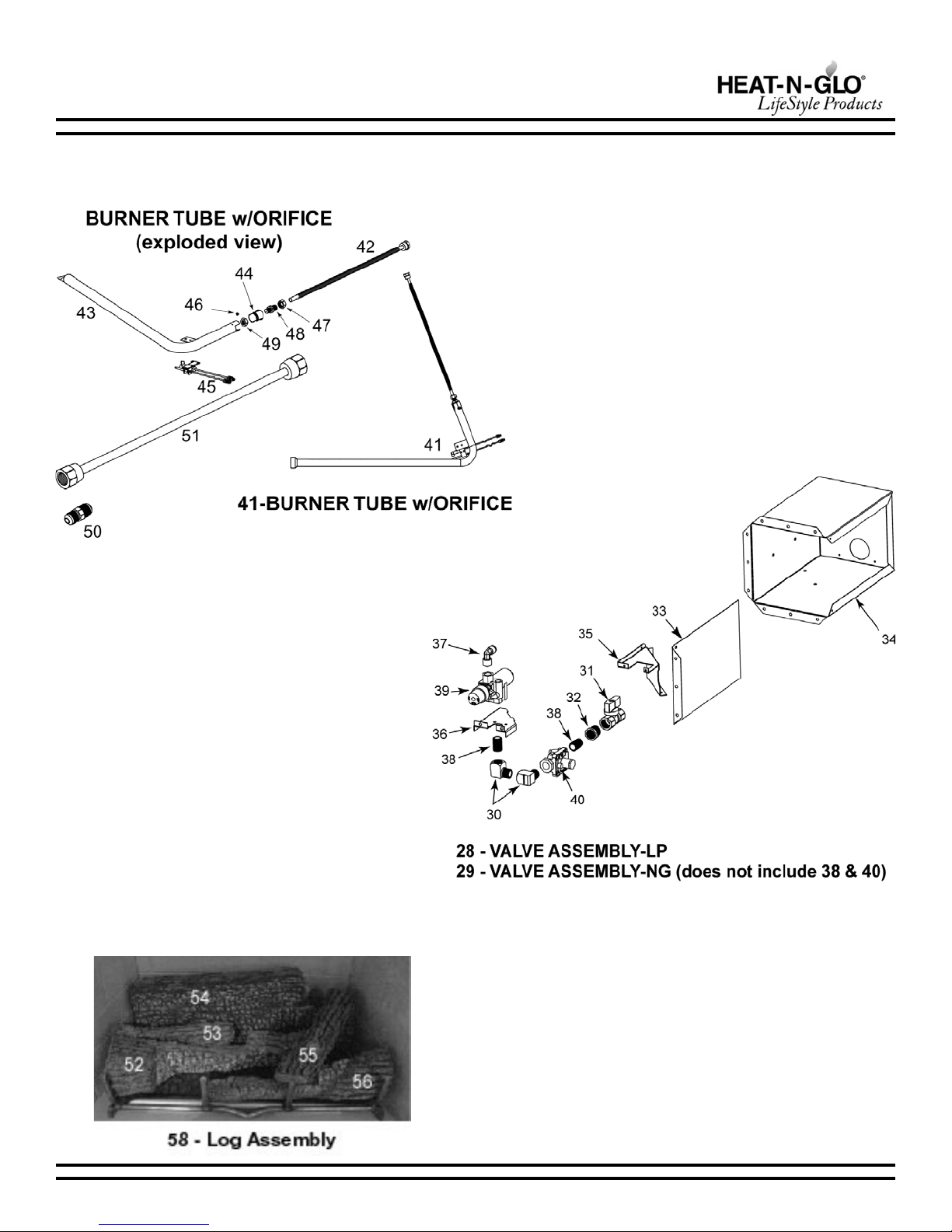
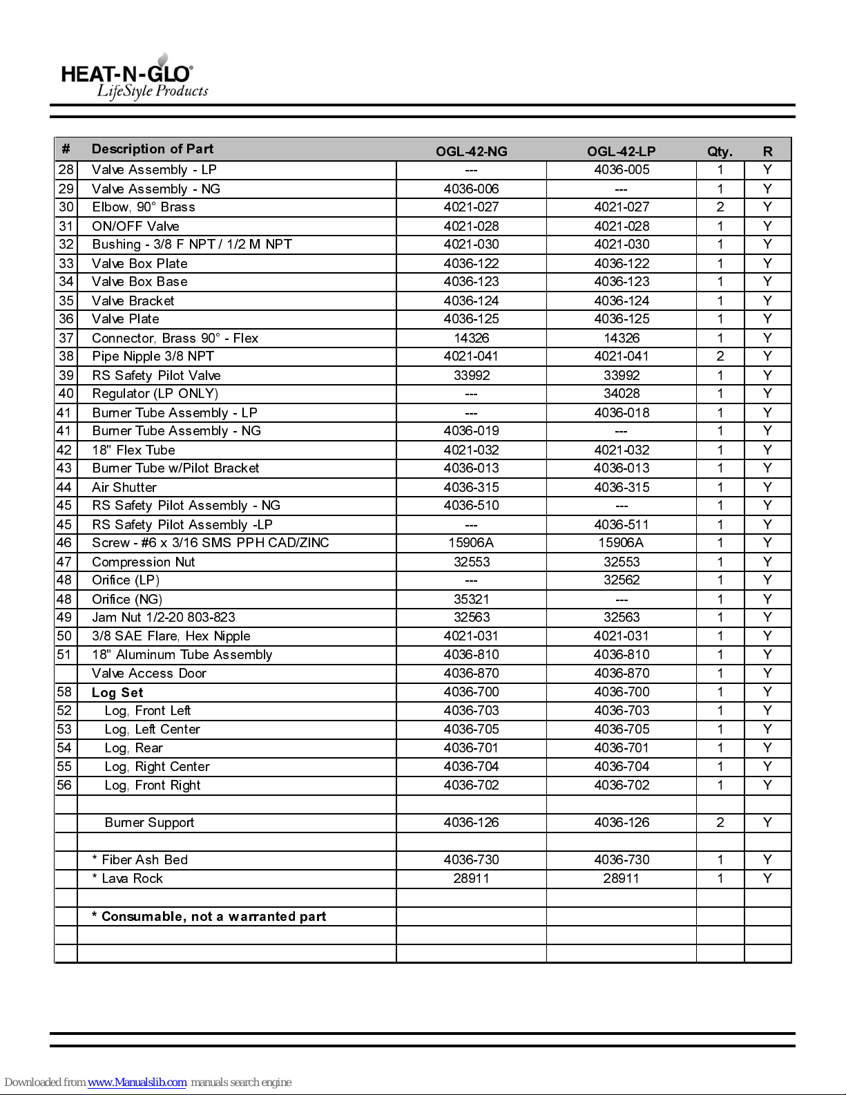
B. Service Parts List ........................................................................................................................................................... 3
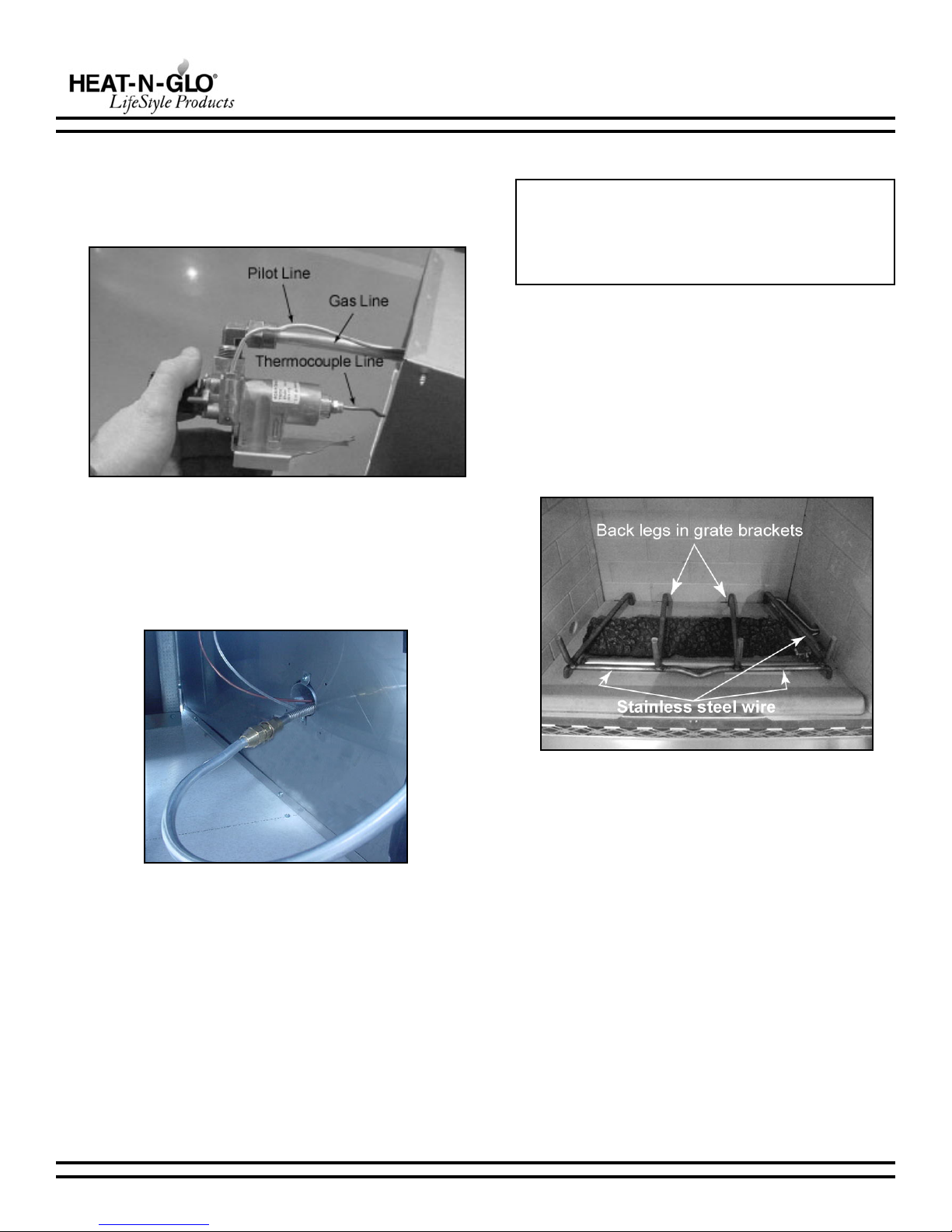
C. Installation of the Log Set .............................................................................................................................................. 5
D. Lighting Instructions for the S Series .......................................................................................................................... 8
E. Maintenance Instructions ............................................................................................................................................... 9
F. Troubleshooting - S Series ........................................................................................................................................ 10
Index ............................................................................................................................................................................ 12
LGOsaGlarutaNsaGenaporP
erusserPmuminiM.c.w.ni0.7.c.w.ni0.11
erusserPmumixaM.c.w.ni01.c.w.ni0.41
HUTBtupnI.xaM000,16000,25
Note: An arrow (Æ) found in the text and in the index signifies change in content.
01/04 4036-903 Rev C 3
OGL-42 INSTALLATION INSTRUCTIONS
This page left blank intentionally.
4 4036-903 Rev C 01/04
OGL-42 INSTALLATION INSTRUCTIONS
B. SERVICE PARTS LIST
See following page for parts descriptions.
01/04 4036-903 Rev C 5
OGL-42 INSTALLATION INSTRUCTIONS
 'HVFULSWLRQRI3DUW 2*/1* 2*//3 4W\ 5
 9DOYH$VVHPEO\/3    <
 9DOYH$VVHPEO\1*    <
 (OERZ UDVV    <
 212))9DOYH    <
 XVKLQJ)1370137    <
 9DOYH R[3ODWH    <
 9DOYH R[ DVH    <
 9DOYH UDFNHW    <
 9DOYH3ODWH    <
 &RQQHFWRU UDVV)OH[    <
 3LSH1LSSOH137    <
 566DIHW\3LORW9DOYH    <
 5HJXODWRU/321/<    <
 XUQHU7XEH$VVHPEO\/3    <
 XUQHU7XEH$VVHPEO\1*    <
 )OH[7XEH    <
 XUQHU7XEHZ3LORW UDFNHW    <
 $LU6KXWWHU    <
 566DIHW\3LORW$VVHPEO\1*    <
 566DIHW\3LORW$VVHPEO\/3    <
 6FUHZ[60633+&$'=,1& $ $  <
 &RPSUHVVLRQ1XW    <
 2ULILFH/3    <
 2ULILFH1*    <
 -DP1XW    <
 6$()ODUH+H[1LSSOH    <
 $OXPLQXP7XEH$VVHPEO\    <
9DOYH$FFHVV'RRU    <

/RJ6HW
   <
 /RJ)URQW/HIW    <
 /RJ/HIW&HQWHU    <
 /RJ5HDU    <
 /RJ5LJKW&HQWHU    <
 /RJ)URQW5LJKW    <
XUQHU6XSSRUW    <
)LEHU$VK HG    <
/DYD5RFN    <
&RQVX DEOHQRWDZDUUDQWHGSDUW
6 4036-903 Rev C 01/04
OGL-42 INSTALLATION INSTRUCTIONS
1. Gas Line and Valve Assembly Installation
Fi ure 1 - Placin the Burner Assembly
Note: Have the gas supply line installed in accordance
with building codes by a ualified installer approved and/or
licensed as re uired by the locality. In the Commonwealth
of Massachusetts, installation must be performed by a
licensed plumber or gas fitter.
a. Place the burner assembly in the appliance, hand-bend
the flexible stainless steel gas line as shown in Figure 1
and feed the thermocouple line, pilot line and stainless
steel flexible gas line through the hole in the right side of
the appliance. Make sure the excess pilot and
thermocouple line is OUTSIDE the box.
b. The appliance is provided with a stainless steel flexible
connector and a listed (and Commonwealth of
Massachusetts approved) tee-handle manual shutoff
valve.
c. Remove the right side of the valve box for easier
installation of the gas line. Set aside.
1) Bend the flanges of the remaining three sides of
the valve box 90° at the perforations (Figure 2),
place a bead of silicone (not provided) on the back
side of the flanges and slide the valve box into the
s uare hole on the side of the FPS enclosure. (If
you are not using an FPS enclosure, the valve
must be located in an accessible position where
one person can operate the valve and light the pilot
simultaneously.) All connections within the enclo-
sure need to be accessible for future maintenance
or troubleshooting.
2) Secure the 3-sided valve box to the FPS enclosure
with the drywall screws provided. See Figure3.
d. Remove the valve from the valve box for ease of assembly
by removing the two screws holding the valve to the valve
bracket.
SAFETY:
This outdoor as lo set must be installed in a UL-listed
outdoor fireplace that has a as knockout on the ri ht side
with the followin minimum firebox dimensions:
Depth: 19 inches
Hei ht: 23 inches
Rear Width: 23 inches
Front Width: 42 inches
Suitable fireplaces would be STS42, OUT42, Montana.
Fi ure 3 - Secure Valve Box to FPS
Fi ure 2 - Remove Ri ht Side of Valve Box & Bend Flan es
C. INSTALLATION OF THE LOG SET
Note: Although knockouts are provided on both sides of the
fireplace, the gas inlet should be routed to the right side of the
fireplace.
01/04 4036-903 Rev C 7
OGL-42 INSTALLATION INSTRUCTIONS
e. Reach through the back access hole of the enclosure
and feed the thermocouple line, aluminum gas line and
pilot line through the rear of the valve box assembly.
Connect to the valve. See Figure 4. Tighten fittings to
eliminate gas leaks.
h. Connect the main gas line to the manual shutoff valve
using ½ male pipe thread (not supplied).
Bend the flange of the right side of the of the valve box
90° at the perforations, place a bead of silicone on the
back side of the flange and replace in the valve box.
Fasten with remaining screws.
i. All connections must be tightened and checked for leaks
with a commercially available, non-corrosive leak check
solution. Be sure to rinse off the solution when done
leak testing.
j. Place a bead of silicone around the inside flanges and
the holes in the corners of the valve access door. Place
the valve box cover on the valve box and secure using
the mounting holes on the edge of the box.
Fi ure 4 - Connect Lines to Valve
f. Place the valve back on the valve bracket in the valve box
and secure using the two screws previously removed.
. Reach through the back access hole of the enclosure and
connect the flexible stainless steel gas line to the soft
aluminum gas line with the male flare connector supplied.
See Figure 5.
Fi ure 5 - Connect Flexline
2. Grate Assembly and Fiber Ash Bed
a. Position the burner tube on the stainless burner supports.
See Figure 1.
b. Place the fiber ash bed on the floor of the firebox, ensuring
that it does not cover the burner.
c. Position the grate assembly over the burner assembly
and fiber ash bed, and center from left to right. The back
legs will be located in the grate brackets.
d. Attach the burner to the grate with the enclosed stainless
steel wire to hold the burner in position. Wrap the wire
around the burner and the grate bar. See Figure 6.
Note: The GR21 grate assembly used in the STS-42,
OUT42, and Montana is not supplied with the OGL42 log
set. If you are installing the log set in another UL-listed
fireplace the GR21 grate can be ordered from Heat-N-Glo
Lifestyle products.
Fi ure 6 - Fiber Ash Bed
Æ
8 4036-903 Rev C 01/04
OGL-42 INSTALLATION INSTRUCTIONS
Fi ure 7 - Rear Lo
Fi ure 8 - Front Ri ht Lo
Fi ure 9 - Front Left Lo
Fi ure 10 - Left Center Lo
Fi ure 11 - Ri ht Center Lo
Fi ure 12 - Lava Rock
4. Lava Rock
Spread a two-pound bag of lava rock (included) between the
burner and the ashlip. See Figure 12.
3. Log Placement
a. Rear Lo
The rear log is placed on the grate against the back wall
of the appliance. See Figure 7.
b. Front Ri ht Lo
Place the front right log on the grate against the front
tines of the grate. See Figure 8.
c. Front Left Lo
The front left log will be located on the grate with the left
side of the log against the left front tine of the grate. The
right side of the log will angle toward the center of the
grate. See Figure 9.
d. Left Center Lo
Place the left center log on the grate behind the front left
log. See Figure 10.
e. Ri ht Center Lo
Place the right center log on top of the front right log and
the rear log. See Figure 11.
01/04 4036-903 Rev C 9
OGL-42 INSTALLATION INSTRUCTIONS
D. LIGHTING INSTRUCTIONS FOR THE S SERIES
10 4036-903 Rev C 01/04
OGL-42 INSTALLATION INSTRUCTIONS
E. AINTENANCE INSTRUCTIONS
1. Cleaning the Burner and Control Compartment
Keep the burner and control compartment clean by brushing
and vacuuming at least once a year. Always turn off the gas
valve before cleaning.
2. Checking Flame Patterns
Check the flame of the burner periodically, making sure the
flames are steady, not lifting or floating. Adjust the air shutter
if necessary. The flame color should be blue with yellow tips.
The thermocouple tip should be covered with flame. See
Figure13.
Fi ure 13 - Thermocouple
3. Ad usting the Air Shutter
To adjust the air shutter, remove the logs from the appliance.
Loosen the screw on the burner air shutter and rotate the
shutter to open. Tighten the screw and reinstall the logs.
4. Logs
a. Cleanin the Lo s
Your gas logs re uire little care. Keep the burner assembly,
logs and burner area surrounding the logs clean by
vacuuming or brushing with a dry paint brush at least twice
a year or as necessary.
CAUTION:
The lo s can et very hot. Handle only when they are cool.
After burnin , the lo s become fra ile, so take care in han-
dlin .
Note:
Always turn off the gas to the pilot before cleaning. For
relighting, refer to lighting instructions in this manual.
Always keep the appliance clear and free from
combustible materials, gasoline, and other flammable
vapors and li uids.
Never obstruct the flow of combustion and ventilation
air. Keep the front of the appliance clear of all obstacles
and materials.
Leave clearance of at least 36 from the front of the
appliance.
The air shutter should not be blocked.
b. Removin the Lo s
Remove the logs in reverse order of placement (see Log
Placement).
5. Stainless Steel Parts
Weather and heat exposure may cause discoloration of
stainless steel parts. This is normal and not warranted.
01/04 4036-903 Rev C 11
OGL-42 INSTALLATION INSTRUCTIONS
smotpmyS sesuaCelbissoPnoitcAevitcerroC
.1.toliptgiltonlliwctaM.aevlavffotussagniaM
.desolc
gnimocnietnodetacolevlavffotusettaterusekaM
.neposienilsag
.b.enilsagetniriA dnanoitisop"TOLIP"otbonkevlavnruT.ctamatgiL
.stgiltilitnurenrubtolipraenctampeeK.sserped
.c"FFO"nisibonkevlaV
.noitisop
peeK.sserpeddnanoitisop"TOLIP"otbonkevlavnruT
.stgiltilitnurenrubtolipraenctam
.d,deggulpsiecifirotoliP
.wolfotsaggniwollaton
foeergedemosdnaslootseriuqerriapersiT
.naicincetecivresdeifilauqallaC.ecneirepxe
.eetotylppussagoN
.ecnailppa
neebsaecnailppaeterusneotgnibmulpetkceC
.enilylppussagetotpudekoo
.ytpmesiknatenaporpeT
.f.enilnikaerbrokniK.enilecalpeR
.2retfatilyatstonlliwtub,stgiltoliP
.noitcurtsnignitgilgniwollofylluferac
.arotgitootelpuocomreT
.esooloot
,tgit-regnifevlavetotdecattaebtsumelpuocomreT
.cnerwatiwnrut8/1asulp
.b.emalftolipkaeW ro/dnanaelC.elpuocomretetflugnetsumemalftoliP
etnotnemegnipmiemalfmumixamroftoliptsujda
.elpuocomret
.c.elpuocomretevitcefeD :swollofsaretemtlovillimatiwelpuocomretetkceC
tcennocdnaevlavetmorfelpuocomretettcennocsiD
etfodnerevlisetotretemetfodaelderet
retemetfodaelkcalbettcennocwoN.elpuocomret
tolipettgiL.elpuocomretetfognibutreppocetot
eT.sgnidaergnikateliwdesserpedbonketpeekdna
,tonfI.Vm41natretaergebdluossgnidaerretem
.elpuocomretecalper
.3,renrubniamotsagoN."NO"toliP
."NO"bonkevlav
.agnitneverpsiegakcolbA
.wolfsag
gnidulcni,noitcurtsborofecifirorenrubettcepsnI
.naicincetecivresdeifilauqallaC.sbewdnasredips
.b.evlavevitcefeD .naicincetecivresdeifilauqallaC.evlavsagecalpeR
.4.nrettapnrubralugerrI.a.stropgolcsirbed&ecI tatecrofottonluferacgnieb,sirbedroeciyawaraelC
.stropetotnisirbedroeci
F. TROUBLESHOOTING - S SERIES
12 4036-903 Rev C 01/04
OGL-42 INSTALLATION INSTRUCTIONS

This manual suits for next models

2

Other Heat & Glo Fireplace Accessories manuals

Heat & Glo LOGS-Cerona36 User manual

Heat & Glo

Heat & Glo LOGS-Cerona36 User manual

Heat & Glo VPK-DV User manual

Heat & Glo

Heat & Glo VPK-DV User manual

Heat & Glo GRL-850-AU Owner's manual

Heat & Glo

Heat & Glo GRL-850-AU Owner's manual

Heat & Glo LOGS-I35 User manual

Heat & Glo

Heat & Glo LOGS-I35 User manual

Heat & Glo Tonic SLR-C User manual

Heat & Glo

Heat & Glo Tonic SLR-C User manual

Heat & Glo 6KX-AU User manual

Heat & Glo

Heat & Glo 6KX-AU User manual

Heat & Glo LOGS-Cerona42 User manual

Heat & Glo

Heat & Glo LOGS-Cerona42 User manual

Heat & Glo SL-550F User manual

Heat & Glo

Heat & Glo SL-550F User manual

Heat & Glo PRIMO-II Series User manual

Heat & Glo

Heat & Glo PRIMO-II Series User manual

Heat & Glo ARC-32 Manual

Heat & Glo

Heat & Glo ARC-32 Manual

Heat & Glo PRIMO-II-48 User manual

Heat & Glo

Heat & Glo PRIMO-II-48 User manual

Heat & Glo 350X-AU User manual

Heat & Glo

Heat & Glo 350X-AU User manual

Heat & Glo LOGS-2128 User manual

Heat & Glo

Heat & Glo LOGS-2128 User manual

Heat & Glo PORTRAIT-6-BK User manual

Heat & Glo

Heat & Glo PORTRAIT-6-BK User manual

Heat & Glo 6000CMOD-IPI User manual

Heat & Glo

Heat & Glo 6000CMOD-IPI User manual

Heat & Glo LOGS-I35FB User manual

Heat & Glo

Heat & Glo LOGS-I35FB User manual

Heat & Glo COSMO32-IFT User manual

Heat & Glo

Heat & Glo COSMO32-IFT User manual

Heat & Glo LOGS-SL750TRS-D User manual

Heat & Glo

Heat & Glo LOGS-SL750TRS-D User manual

Heat & Glo DRIFTWOOD-C32 User manual

Heat & Glo

Heat & Glo DRIFTWOOD-C32 User manual

Heat & Glo LOGS-750TRS-E User manual

Heat & Glo

Heat & Glo LOGS-750TRS-E User manual

Heat & Glo LOGS-350TRS-D User manual

Heat & Glo

Heat & Glo LOGS-350TRS-D User manual

Heat & Glo Firescreen User manual

Heat & Glo

Heat & Glo Firescreen User manual

Heat & Glo LOGS-6000G User manual

Heat & Glo

Heat & Glo LOGS-6000G User manual

Heat & Glo LOGS-I30FB User manual

Heat & Glo

Heat & Glo LOGS-I30FB User manual

Popular Fireplace Accessories manuals by other brands

Napoleon GD849KT installation instructions

Napoleon

Napoleon GD849KT installation instructions

Hearth & Home PVLP-SLP-AU installation instructions

Hearth & Home

Hearth & Home PVLP-SLP-AU installation instructions

Miles Valor L1 1500KNGK installation manual

Miles

Miles Valor L1 1500KNGK installation manual

Escea DF Series quick start guide

Escea

Escea DF Series quick start guide

Bluegrass Living B24EL-1 installation instructions

Bluegrass Living

Bluegrass Living B24EL-1 installation instructions

Hearth and Home Technologies PHSI-MCE installation instructions

Hearth and Home Technologies

Hearth and Home Technologies PHSI-MCE installation instructions

Valor HORIZON H4 Series installation instructions

Valor

Valor HORIZON H4 Series installation instructions

Dimplex CDFI-BX1000 Service manual

Dimplex

Dimplex CDFI-BX1000 Service manual

Travis Industries Illuminations 4915 installation instructions

Travis Industries

Travis Industries Illuminations 4915 installation instructions

Valor Horizon 602CFB installation manual

Valor

Valor Horizon 602CFB installation manual

Valor 555CFK Installation and operating instructions

Valor

Valor 555CFK Installation and operating instructions

Superior Fireplaces VRE4036 Series Assembly instructions

Superior Fireplaces

Superior Fireplaces VRE4036 Series Assembly instructions

Empire Comfort Systems 37506 instructions

Empire Comfort Systems

Empire Comfort Systems 37506 instructions

Napoleon GPFTR Installation

Napoleon

Napoleon GPFTR Installation

Napoleon DVLINEAR36 instructions

Napoleon

Napoleon DVLINEAR36 instructions

White Mountain Hearth PONDEROSA LS-18P-2 Installation instructions and owner's manua

White Mountain Hearth

White Mountain Hearth PONDEROSA LS-18P-2 Installation instructions and owner's manua

Desa W23OT Assembly and installation instructions

Desa

Desa W23OT Assembly and installation instructions

pleasant hearth BG7-246M manual

pleasant hearth

pleasant hearth BG7-246M manual

manuals.online logo
manuals.online logoBrands
  • About & Mission
  • Contact us
  • Privacy Policy
  • Terms and Conditions

Copyright 2025 Manuals.Online. All Rights Reserved.