HP 64653A User manual

HP64000
Logic Development
System
Model 64653A
8086/8088 Dedicated
lnterface Card
@H"=BL'"=JJ

CERTIFICATION
Hewlett-packard Company certifie.s thaf this product met its published specifications at the
time of shipment from tne factory. Hewlett-Packard further certifies that its calibration
measurements are traceable to the lJnited States Nationat Bureau of Standards, to the extent
allowed by the Bureau's calibration tacility, and to the calibration facilities of other
lnternational Standards Organization members.
WARRANTY
This Hewlett-Packard system product is warranted against defects in materials and
workmanship for a period of 90 days f rom date of installation. During the warranty period, HP
will, at its options, either repair or replace products which prove to be defective.
Warranty service of this product will be performed at Buyer's facility at no charge within HP
service travel areas. Outside HP service travel areas, warranty service will be performed at
Buyer's facility only upon HP's prior agreement and Buyer shall pay HP's round trip travel
"rpens"s. ln att ott"rer cases, products must be returned to a service facility designated by HP.
For products returned to HP for warranty service. Buyer shall prepay shipping charges to HP
and HP shall pay shipping charges to return the product to Buyer. However, Buyer shall pay all
shipping charges, duties, and taxes for products returned to HP from another country.
HP warrants that its software and firmware designated by HP for use with an instrument will
execute its programming instructions when properly installed on that instrument. HP does not
warrant that the operation of the instrument, or software, or firmware will be uninterrupted or
error free.
LTMITATION OF WARRANTY
The foregoing warranty shall not apply to defects resulting from improper or inadequate
maintenance by Buyer, Buyer-supplied software or interfacing, unauthorized modification or
misuse, operation outside of the environmental specif ications f or the product, or improper site
preparation or mai ntenance.
NO OTHER WARRANTY IS EXPRESSED OR IMPLIED. HP SPECIFICALLY DISCLAIMS THE
IMPLIED WARRANTIES OF MERCHANTABILITY AND FITNESS FOR A PARTICULAR
PURPOSE.
EXCLUSIVE REMEDIES
THE REMEDIES PROVIDED HEREIN ARE BUYER'S SOLE AND EXCLUSIVE REMEDIES. HP
SHALL NOT BE LIABLE FOR ANY DIRECT, INDIRECT, SPECIAL, INCIDENTAL, OR
CONSEQUENTIAL DAMAGES, WHETHER BASED ON CONTRACT, TORT, OR ANY OTHER
LEGAL THEORY,
ASSISTANCE
Product maintenance agreements and other customer assistance agreements are available for
H ew lett - P ac k ar d p rod uct s.
For any assistance, contact your nearest Hewlett-PaclrardSales and Service Off ice. Addresses
are provided at the back of this manual.
cw&A 2/81

SERVICE MAIIUAI
troDEr 6\6SZa
8086/8088 DEDTCATED TITTERFACE CARD
REPAIB IIIJMBERS
Ttris manual applies directJLy to
8085/8088 Dedicated Interface Cards
with repair number prefixes 2:!10A.
O COPYRIGHT HEWLETT-PACKARD COMPANY 1982, 1983
LOGIC SYSTEMS DIVISION
COLORADO SPRINGS, COLORADO, U.S.A.
ALL RIGHTS RESERVED
Manua1 Part Number 6\5>l-909o\
Mierofiche Part Number 5h553-9080L PRIMIED: FEBRUARY 1983

SAFETY SUMMARY
The lolowlng generat salety precaulions must be obserued during all phases of operation, service,
and repair oi ttris instrument, Faiture to comply wtth these precautions or with specillc warnings
elsewhere in this manual vlotates salety standards ol destgn, manufacture, and inlended use ol lhe
instrument. Hewtett-Pacftard Company assumes no ltabilily lor the cuslomer's lailure to comply
with these requirements,
GROUND THE INSTRUMENT.
To minimize shock hazard, the instrument chassis and cabinet must be connected to an electrical
ground. The instrument is equipped with a three-conductor ac power cable. The power cable
must either be plugged into an approved three-contact electrical outlet or used with a three-contact
to two-contact adapter with the grounding wire (green) firmly connected to an electrical ground
(safety ground) at the power outlet. The power lack and mating plug of the power cable meet
lnternational Electrotechnical Commission (lECt safety standards.
DO NOT OPERATE IN AN EXPLOSIVE ATMOSPHERE.
Do not operate the instrument in the presence of flammable gases or fumes. Operation of any
electrical instrument in such an environment constitutes a definite safety hazard.
KEEP AWAY FROM LIVE CIRCUITS.
Operating personnel must not remove instrument covers. Component replacement and internal
adjustments must be made by qualified maintenance personnel. Do not replace components with
power cable connected. Under certain conditions. dangerous voltages may exist even with the
power cable removed. To avoid injuries, always disconnect power and discharge circuits before
touching them.
DO NOT SERVICE OR ADJUST ALONE.
Do not attempt internal service or adjustment unless another person, capable of rendering first atd
and resuscitation, is present.
DO NOT SUBSTITUTE PARTS OR MODIFY INSTRUMENT.
Because of the danger of introducing additional hazards, do not install substitute parts or perform
any unauthorized modification of the instrument. Return the instrument to a Hewlett-Packard
Sales and Service Office for service and repair to ensure that saiety features are maintained.
DANGEROUS PROCEDURE WARNINGS.
Warnings, such as the example below, precede potentially dangerous procedures throughout this
manual. lnstructions contained in the warnrngs must be followed.
Dangerous voltages,
Use extreme caulion capable ol causing death, are present in this instrument.
when handling, tesling, and adjusting.
55-t-t /t)

Model 5l+55U,
Section
I
L-3".
1-4.
L-9.
L-Lz.
1-L3.
a-L5.
rI
2-L.
2-3.
2-5.
2-5.
2-8.
III
IV
v
VI
5-t.
6-5.
5-5.
6-7.
6-rz.
WI
VIII
8-1.
B-3.
B-I+.
8-5.
8-7.
8-8.
8-L8.
8-3)+.
Tab]-e of Contents
TABTE OF CONTENTS Page
GENERAT INFORMATION. .. . .1.-1
Introduction.. ...1--L
Instruments Covered By Ttris Manual ..,..L-1-
Description... ....,1,-2
Electrical Characteristics ..L-2
Equipment Required but not Supp1ied. ...1--h
Related Manuals ....1-l{
INSTAILATION.. .....2-t
fntroduction.. .....2-1,
Initial Inspection.... ..2-t
Operating Environment... .....2-2
Storage and Shipment.. ..2-2
0PERATION .....3-1
PERT'ORMANCE VERICATIOI{ AI{D TROUBLESHOCTIING ..\.7
ADJUSTI,IEMS.... ,,.,5-L
REPTACEABLE PARTS .,6-T
fntroduction.. .....6-t
Abbreviations. .....5-t
Beplaceable Parts List. ......5-t
Ordering Information.. . . ,... ,6-Z
Direct Mail Order System. ....6-Z
MANUAT CHANGES .. . . .7-1"
THEORY AND SCHEMATICS.. ......8-1
fntroduction.. ....8-1
Logic Conventions... ...8-f
Logic Levels ..8-1
Power Supplies ... . .B-1
Theory. ..8-r
Overwiew. .....8-L
Block Description... ....8-4
t'tnemonics .....8-6

Model 6\5SSe
Figure
t-L.
6-t.
6-2.
8-r.
8-2.
8-3.
8-1.
8-5.
Table
6-t.
6-2.
64.
8-1.
B-2.
8-3.
tist of Illustrations
List of Tables
LIST OF ILLUSTRATIONS
Title Page
Model 6l+6SZa, 8085/8088 Dedicated Interface Card"' "L-0
nxltoaea View Users Plug. .,6'7
Model 5\651e, Block Diagram . .. . ..8-2
Model eUelle Component Locator. .... .B-fl+
Service Sheet t.... "8-15
Model 5\6Sll Component Locator. ,... '8-a6
Service Sheet 2..., "8-17
IIST OT' TABTES
TitIe Page
Reference Designators and Abbreviations. -.....6-3
Replaceable Paits List. . . .5-l+
List of Manufacturers' Codes ..6-5
Mnemonics ..8-9
Logic Symbols ..8-11
Schematic Diagram Notes ..8-13
iil(iii blank)


General Information--Mode1 6l+553A
1-0
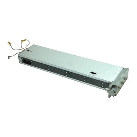
Figure L-1. Mode)- 5\5fiA 8085/8088 Dedicated Interface Card

General fnformation- -I,todel 6l+6rZA,
SECTION T
GENERAT INFONMATION
1-1. TilIRODUCTION.
1-2. This Service Manual contains information required to insta11, test and
service the Hewlett-Packard Mode1 6t+5>Ze, 8086/8088 Dedicated Interfaee
Card.
1-3. Shown on the title page is a microfiche part number. This number can be
used to order a h X 5-inch microfilm trinsparency of the manual. Each
microfiche contains up to !5 photoduplicates of the manual pages.
1-h. INSTBT,I"IENTS co\lERED By TTIIS MANUAI.
1-1. Attached to the instrtrment or printed on the printed circuit board is
the repair number. The repair number is in the form: OOOOAOOOO. It is in
two parts; the first four digits and the letter are the repair prefix, and the
last five are the suffix. ttre prefix is the same for all identicaL instruments,
3he suffix, however, is assigned sequentially and is different for each
instrrrment. Ttre contents of this manual apply to instruments with the repair
number prefix(es) tisted under nEpArR IIITMBERS on the titre page.
1-5. An instrument manufactured after the printing of this manual may have
a repair number prefix tbat is not listed on the title page. This unlisted
repair number prefix indicates that the instrument is different from those
described in this manual. The manual for this newer instrument is aecompanied
by a Manual Changes Supplement. Tlre supplement contains "-"h.rg"
information" that explains how to adapt the manual for the newer instrument.
L-T - In addition to change information, the supplement contains
information for correcting errors in the manual. To keep this nanual as
current as possible, Hewlett-Packard recommends that you periodically request
the latest Manual Changes Supplement. Ihe supplement for this r.rrrru.l is
identified with the manual print date and part numbero both of which
appear on the manual title page. Complimentary copies of the supplement are
available from llewlett-Paekard.
1--8. For information concerning a repair number prefix that is not listed on
the title page or in the Manual Changes SuppJ-ement, eal-I your nearest
Hewlett-Packard off ice .
L-L

General Information--Mode1 6\65Y
1-g.DESCRTPTTO}I.
1-j-0. The 6\651A 8085/8088 Dedicated fnterfaee Card connects the 6l+5eOS
Logic AnaLyzer 'or tie 163OA/D Logic Analyzer to an 8085 or an 8088
microprocessor system. The Interface card samples all necessary information
about a bus trarnsaction at the proper time, combines this information into a
concise form, and then sends all information to the State AnaLyzet at one
time. Ttre CpU can be in either "min" or "max" mode of operation and operate at
"i;"* input rates of up to 10 MHz. If the CPU is in "max" mode the
Interface card can, at the user's option, completely degueue the instruction
stream and send only executed instructions to the analyzer'
L.LL. ETECTRICA], CHARACTERISTICS.
Maximum clock speed:
Signal line loading:
Outputs:
Input:
Polrer Consumption:
tO Mllz
Three tS TTL loads on the CLK line plus
approximately 6O pP capacitancel one
LS flt load for alL other monitored
signal lines and approx t+: PF
capacitance.
STIMULUS and HAIT are tS TTL open
collector active-Iow outputsl maximum
current sinking, 6 mn,.
ACK, acknowJ-edge for STIMUTUS line
active Iow, fIL level.
up tcr L A at +l Vdc ma:<imum, suPPlied
by Model 5\5eOS Logic State/Software
Analysis Subsystem or Model L53OA/D Logic
Analyzer.
L-Lz. EQUIPMENT REQUIRED BUT NOT SUPPLIED.
1-13. For a complete SLOOO State Analysis subsystem:
5\5ZtA State Anatysis Control Board
6\5zze a:nd.f or 6l+623A State Analysis Acquisition Board
6\6501, General Purpose Preprocdssor
For a complete L53o^/D system:
L63oAlD
tO269 Interface Module
t-2

GeneraL lnformation--Model 6\6>Sl,
1-1b. REIAIED MANUATS
Service Manuals.
State Analysis Control Manual
state Analysis Aequisition Manual (ho enanner or 20 channer)
State Data Probe Manua1
General Purpose Preprocessor Manual
Logic Analyzer L63aA/D
Operating Manuals
State Analyzer Manual
General Purpose Preprocessor Manual
8085/8088 Interface Card Manuat
Logic Analyzer \63OA/D
L-31$-\ blank)


Ins tallat ion- -Mode L 6\553A
SECTION II
INSTATTATION
2.L. I}ITRODUEfION.
2-2' This section contains information for installing and removing the
Model 5l+653A. rncruded are initial inspection pro".J*res and instructions
for repacking the instrument for shipment.
2.3. I}IITIAL INSPECTIO$.
2-L.Inspect the shipping container for damage. If the shipping container
or cushioning material is damaged, it should be kept until contents of the
shipment have been checked for compJ-eteness and the instrument has been
checked mechanically and e1ectriea11y. Procedures for checking eleetrical
performance are given in Section IV. If the contents are incomplete, if there
is mechanical damage or defect, or if the instrument does not pass the
Performanee Tests, notify the nearest Hewlett-Packard office. Keep the
shipping materials for earrier's inspection. The IIP office will ,,""urr!. for
repair or replacement at HP's option without waiting for claim
settlement.
2.5. INSTATLATION.
2-6. rnstallation in tlne 6\65o4 General purpose preprocessor.
a, Remove power from the 5I+OOO station.
b. Connect W6 from the small General Purpose Preprocessor eard to JI+ on
the Interface Card.
c. Connect W3 from the Large General Furpose Preproeessor card to J3 on
the fnterface Card
d. Lower the Interface Card into the Preprocessor so that the component
slde fits inside the pod.
e. Fit the Pod Cover hinges into hinge slots on the General purpose
Preprocessor pod. Lower the cover over the Interface Card and fasten
dovun with screws.
To avoid possible damage from statie discharge, always
eonnect assembly (Wl+) from the Preprocessor endcap to J!
on the Interface Card.
2-L

Instaltat ion- -Mode L 5\653A
2-7. Installation in Modet LO259A Interface.
a. Connect WL from JL on the General Purpose Interface Card in the
LO269A to J)+ on the Dedicated Interface Module.
b. Connect W2 from J3 on the General Purpose Interface card in the
LO259A to J3 on the Dedicated Interface Module.
c. Fit the Dedicated Interface Module assembly into hinge sLots on
LOZ61A General Purpose Probe Interface Pod. Lower the cover
fasten dor^rn with screws.
2-8. OPERATING ENVIRONI''E}IT.
Z-9, fhe instrument may be operated in environments within the following
limits:Temperature... ...ooc to ,5"C
e5/,
metres (L5 000 ft)
However, the instrrrment should also be protected from temperature extremes which
cause condensation within the instrument.
2-L0. STORAGE AIID SIIIPI'IEIIT.
z-LL. Environment,
2-L2. Ttre instrument may be stored or shipped in environments within the
following limits:
Temperature... ..-lrooc to +T5oC
Humidity. . .. .uP to 90%
Altitude ...up to 11 300 metres (50 000 ft)
The instrument should also be protected from temperature extremes which cause
condensation within the instrument.
2-L3. Packaging.
2-L\. Original Packaging. Containers and materials identical to those used in
factory packaging are available through Hewlett-Packard offices. If the
instrument is being returned to Hewlett-Packard for servicing, attach a lag
indicating the type of service required, return address, model number, and full
serial number. A1so, mark the container FRAGILE to ensure careful handling.
In any correspondence, refer to the instrument by model number and fu1I serial
number.
the
and
2-2

Installation- -Mode I 6\553h
2-L5. Other Packaging. The following general instructions should be used. for
repacking with commercially available materials:
a. I.Irap instrument in heavy paper or plastic. (rf shipping to
Hewlett-Packard office or service center, attach tag indicating serrrlce
reguired, return address, moder number, and fu11 serial number.)
b. Use strong shipping eontainer. A double-wa1l carton made of J!0-poturd
test material is adequate.
c. use a layer of shock-absorbing material T0 to 100 mm (s- to lr-inch)
thick around all sides of the instr"ument to provide firm cushioning and
prevent movement inside container
d. Seal shipping container securely.
e. Mark shipping container FRAGILE to ensure careful handling.
f. In any correspondenceo refer to instrunent by model number and full
serial number.
2-3/Q-\ blank)


Operation- -Model 6l+GXe
SECTION III
OPERATION
operation of the Model 5r+G53A is beyond the scope of this manual.
3-t/ (g-z brank)


Performance Verification and Troubleshooting
SECTIO}I IV
PERTORMANCE VERIFICATIoN AIiID TRoUBLESIIoCEING
Ttre llodel 5\553A does not have a perfozmance verification test. If a
problem beeomes apparent, perform the following troubleshooting procedure:
a. If using tue 6l+6z05 State Anabyzer run the Performance Verifieation
for the Model 5l+55a* General Purpose Preprocessor. If using the
L631A/D Logic fuialyzer run the Performance Verification for that
instrument. Refer to the service manuals for the 5\6SOg ""i
L531A/D for performance verification instructions.
b. If there are no failures, assume the problem is in tfre 5t+553e.
Check the eable and connections for shorts and continuity.
c. Refer to the fllustrated Parts Breakd.own (figure 5-L) and
replace the pC board assembly (Hp p/N 6\G>3_66ZOZ).
NO{TE:
Section VfII describes the functions perforrned by t]ne 5l+6534 pC Board
t+-L/ (h-e utant<)

This manual suits for next models
2
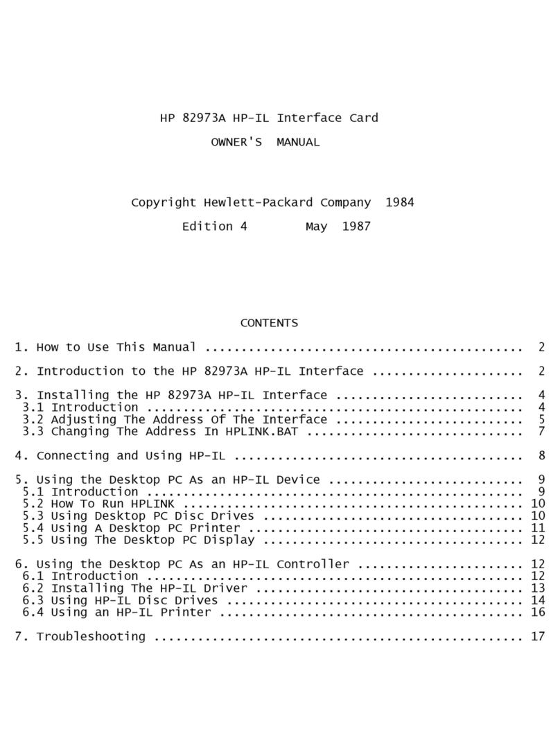
Table of contents
Other HP Recording Equipment manuals
Popular Recording Equipment manuals by other brands

Spycentre Security
Spycentre Security 1416 quick start guide

Steinberg
Steinberg AXR4T Getting started

Parker SSD Drives Inc
Parker SSD Drives Inc L5354 ControlNet Technical manual

Audio Technica
Audio Technica ARTIST ELITE 5000 Installation and operation

Solid State Logic
Solid State Logic Super-Analogue Outboard X-Rack E Series user guide

Involve Audio
Involve Audio Surround Master user manual