HP 7414A Service manual

HP Archive
This vintage Hewlett Packard document was
preserved and distributed by
www.hparchive.com
Please
visit
us
on the web !
Scanned by on-line curator: Tony Gerbic
** For FREE Distribution Only ***

OPERATING
AND
SERVICE
MANUAL
THERMAL-TIP
RECORDER
7414A
HEWLETT
i:I
PACKARD

rr
,
(
",MANUAL
CHANGES
MODEL 7414A
THERMAL-TIP
RECORDER
(MANUAL
TITLE)
MANUAL
SE
RIA LS PRE FI
XED
_----"1"-"1'-'4""'5~A~
_
MANUAL
PRINTED
MARCH,
1972
MAKE
ALL
CHANGES
IN
THIS
MANUAL
ACCORDING
TO
THE
ERRATA
BELOW.
ALSO
CHECK
THE
FOLLOWING
TABLE
FOR
YOUR
INSTRUMENT
SERIAL
PREFIX
(FIRST
THREE
DIGITS
OF
AN
EIGHT
DIGIT
SERIAL
NUMBER)
AND
MAKE
ANY
LISTED
CHANGE(S)
IN
THE
MANUAL.
SERIAL
PREFIX
MAKE
MANUAL
CHANGES
SERIAL
PREFIX
MAKE
MANUAL
CHANGES
ALL
INSTRUMENTS
ERRATA
1
?O?A
f"'l-lANr.E 1
1207A
CHANGE 2
ERRATA
Page
5-4,
Paragraph
5-15,
Step
g:
Page
5-5,
D,
3,
Step
c:
Page
5-10,
Step
a(4):
Page
5-23,
Paragraph
5-47,
Step
g:
Page
5-25,
Figure
5-14:
Page
6-6,
Table
6-1:
Page
6-12,
Table
6-1:
Page
6-14,
Table
6-1:
Page
6-16,
Table
6-1:
Change
reference
to
Paragraph
5-57
to
Paragraph
5-59.
Change
Figure
6-15
reference
to
Figure
5-4.
Should
read
"
...
by
levering
from
front
of
top
bar
...
"
Change
step
to
read
"Remove
snap
ring
holding
sprocket
to
drive
roller
shaft
using
snap
ring
pliers.
"
C-ring
0510-1017
shown
has
been
changed
to
snap-ring
0510-1012,
which
must
be
removed
with
snap-ring
pliers.
Add
on
A3MP1,
7124-1605,
Label
59-61
(Hz).
Change
A3J6,
receptacle
to
1251-2995,
and
A3J5
to
9100-3198.
Change
A9T1
to
07754-60470.
After
A10MP5,
add
attaching
part
0510-1012;
Ring,
retaining.
A10A1MP26
was
changed
in
error;
see
Change
1.
Add
to
Option
008,
7124-1604,
Label
49-51
(Hz).
March,
1972
DATE
PUB.
100-1
07414-91999
MANUAL
PART
NUMBER
A
SUPPLEMENT

CHANGE
1:
CHANGE 2:
MANUAL CHANGES,
MODEL
7414A
(Cont'd)
Page
6-14,
Table
6-1:
On
A10A1MP26,
Add
07754-00880
Spring,
Solenoid
Adjustment;
Delete
(1)
07754-00840
Spacer
and
(3)
07754-00860
Shim.
Page
6-13,
Table
6-1:
Delete
A10W1,
Cable,
interlock.
Page
6-27,
Figure
6-12:
Delete
INTERLOCK
ASSEMBLY
at
bottom
center
of
schematic;
Substitute
a
black
jumper
across
the
pins
on
the
Transfer
Board
A3A1.
r
I
I
I
I
I
I
1,
J
0-18937-4
0-18930-6
March,
1972
- 2 - A
)
I
)
1
t
I
I
,
I
(
(

~MANUAL
CHANGES
MODEL
7414A
THERMAL-TIP
RECORDER
(MANUAL
TITLE)
MAN
UA
L
SE
RIA LS PR EFI
XED
-=1=1c...:.
4
.L.5.:..:A:....-
_
MANUAL
PRINTED
MARCH,
1972
MAKE
ALL
CHANGES
IN
THIS
MANUAL
ACCORDING
TO
THE
ERRATA
BELOW.
ALSO
CHECK
THE
FOLLOWING
TABLE
FOR
YOUR
INSTRUMENT
SERIAL
PREFIX
(FIRST
THREE
DIGITS
OF
AN
EIGHT
DIGIT
SERIAL
NUMBER)
AND
MAKE
ANY
LISTED
CHANGE
IS)
IN
THE
MANUAL.
SERIAL
PREFIX
ALL
INSTRUMENTS
!'.!.
NEW OR
REVISED
ITEM
.6
ERRATA
MAKE
MANUAL
CHANGES
ERRATA
SERIAL
PREFIX
MAKE
MANUAL
CHANGES
Page
5-22,
Figure
5-12:
On
Speed
Control
Connections,
Pin
3
connects
to
ORANGE
wire
and
Pin
4
connects
to
YELLOW
wire.
Page
5-28,
Figure
5-18:
In
lower
right
corner,
specification
for
SHAFT
END
PLAY
of
gearbox
should
be
0.007
inch
(0.018
rmn).
April,
1972
DATE
PUB.
100-1
07414-91999
MANUAL
PART
NUMBER
B
SUPPLEMENT

I
I
I
I
I
I
I
I
I
I
I
I
I
1
)
07414·1
HEWLETT
~
PACKARD
MODEL
7414A
THERMAL-TIP
RECORDER
SERIALS
PREFIXED:
1145A
This manual applies directly to
HP
Model 7414A
Thermal Tip Recorders having serial numbers pre-
fIxed 1145A.
OTHER
PREFIXES:
For instruments having prefixes lower than 1145A,
refer to Appendix I, Backdating Supplement. For
higher prefixes,
see
the manual change sheets pro-
vided.
OPERATING
AND
SERVICE
MANUAL
0741
4-91999
Copright
1972
Hewlett-Packard
Medical
Electronics
Division
175
Wyman
Street
Waltham,
Massachusetts
02154
PRINTED, MARCH 1972
/

Table
of
Contents
TABLE OF CONTENTS
Model 7414A
Paragraph
Page
Paragraph
Page
SECTION
I,
GENERAL
INFORMATION
1-1
4-35. Paper Feed 4-9
I-I.
Introduction
1-1
4-37. Recorder Power Supply and
1-3. Four-Channel Recorder
1-1
Regulator Circuits 4-9
1-9. Applications and Specifications
1-1
4-39. Recorder
DC
Power Supplies 4-9
1-13. Accessories
1-1
4-41. Regulator/Oscillator .4-11
4-49. Marker Circuits .4-11
SECTION
II,
INSTALLATION
2-1
4-54.
440
Hz
Oscillator
.4-12
2-1. Initial Inspection
2-1
4-57. 2400
Hz
Oscillator
.4-12
2-3. Mechanical Check
2-1
2-5. Performance Tests
2-1
SECTION
V,
MAINTENANCE
5-1
2-7. Damage Claims
2-1
5-1. Introduction
5-1
2-9. Storage
2-1
5-3. Test Equipment and Lubricants
5-1
l"
2-11. Installation
2-1
5-5. Performance Checks
5-1
2-13. Preamplifier Installation
2-1
5-8. Variable Line Voltage
5-2
2-15. Power Connections
2-1
5-10. Preventive Maintenance 5-2
2-18 Signal Connections
2-1
5-12. Operational Checks and Inspection 5-2
2-22. Tape System Connections 2-2 5-16. Cleaning 5-9
2-24. Remote Control and Marker Connections 2-2 5-18. Lubrication
5-9
5-20. Electrical Checks
.5-10
SECTION
III,
OPERATION
3-1
5-22. Adjustments and Minor Repairs
.5-10
3-1. Introduction
3-1
5-24. Paper Drive Adjustments
.5-10
3-3. Control Locations
3-1
5-29. Stylus Adjustments
.5-12
3-5. System Operation
3-1
5-38. Corrective Maintenance .5-18
5-40. Galvanometer Removal
SECTION
IV,
PRINCIPLES OF OPERATION
4-1
and Replacement
.5-19
4-1. Introduction
4-1
5-43. Drive Unit Removal and Replacement .5-21
4-4. Preamplifier Power Supply Circuits
4-1
5-46. Paper Table Disassembly for Drive
4-7. Recorder Signal Circuits
4-1
Roller Replacement
.5-23
4-11. Stylus Linkage
4-1
5-48. Gearbox Removal and Overhaul
.5-23
4-13. Galvanometer Position Feedback
4-1
5-55. Solenoid Adjustment
.5-34
4-17. Galvanometer Damping 4-2 5-58. Marker Assembly Maintenance ·5-34 I
4-20. Heat Control Circuit 4-2
4-22. Power Control Circuits 4-2 SECTION
VI,
RECPLACEABLE PARTS
6-1
4-26. Chart Drive 4-7 6-1. Introduction
6-1
4-28. Chart Motor 4-7 6-4. Reference Designations
6-1
4-30. Speed Control 4-7 6-9. Ordering Information 6-2
LIST OF ILLUSTRATIONS
Figure
Page
Figure
Page
I-I.
Model 7414A Recording System 2-5. Tape System Connections Using Control
and Optional Configurations 1-0 Sections 4681A and 4682A 2-6
1-2. 8800 Series Preamplifiers
1-3
2-6. Remote Control and Marker Connections 2-7
2-7. Option 001 Rack Mounting Kit
2-8
2-1. Recorder Access for Receiving Inspection 2-2
2-2. Recorder Rear Panel Connections and Fuse 3-1. 7414A Recording System, Control
Locations.
2-3 Locations 3-2
2-3. Recorder and Mobile Cart Power 3-2. Paper Loading Procedure 3-3
Connections 2-4
2-4. 7414A System
Input
Cable Preparation 2-5 4-1. Model 7754A Recorder, Block Diagram 4-0
07414-1

Model
7414A
Table
of
Contents
LIST OF ILLUSTRATIONS
(continued)
Figure
Page
Figure
Page
.6-22
.6-23
.6-24
.6-25
.5-32
.5-33
.5-33
.5-34
.6-3
Model 7754A Recorder
(End
Itern)
Unit Housing
Al
(07754-60270), Parts
Location Diagram
.....
.6-19
Control Panel A2
(07754-60240)
Subassemblies,
Parts Location Diagram .6-19
Control Panel A2 Schematic Diagram .6-20
6-4.
6-1.
6-2.
6-3.
5-22. Overriding Clutch Lubrication
(Secondary Shaft)
5-23. Gearbox Shaft
End
Play Adjustment
5-24. Gearbox
Input
Chain Tension
Adjustment
.....
5-25. Marker Assembly Adjustment and
Removal .
6-5. Control Switch Board A2A1(07754-60120),
Component Location
Diagram.
. . . . 6-21
6-6. Heat
Potentiometer
Board A2A2 (07754-60130),
Component
Location Diagram .
..
.6-21
6-7. Preamplifier Power Supply Board A2A3
(07754-60140)
Component
Location
6-8. Power Supply A3 (07754-60050)
Subassemblies, Attachments
6-9. Power Supply A3, Parts Location Diagram
6-10. Power Supply A3, Schematic Diagram
(Less A3A1) .
6-11. Transfer Board
A3Al
(07754-60150),
Component
Location Diagram
...
6-26
6-12. Transfer Board
A3Al,
Schematic Diagram
..
6-27
6-13. Driver Amplifier A4, A5, A6, A7 (07754-60170)
Component
Location
Diagram.
. . . . 6-28
6-14. Driver Amplifier A4, A5, A6, A7;
Schematic Diagram 6-29
6-15. Regulator/Oscillator A8
(60
Hz, 07754-60180),
or
A9
(50
Hz, 07754-60181),
Component
Location Diagram and
Schematic.
. . . 6-30
6-16. Drive Unit
AI0
(07754-60250)
Subassemblies,
Parts Location Diagram 6-31
6-17. Gearbox
AI0Al
(07754-60040),
Parts Location
Diagrams . . . . . . . . . . . . . 6-32
6-18. Galvanometer
All,
A12, A13,
A14
(07754-60070), Parts Location Diagram .6-33
6-19. Marker A15, A16
(07754-60350),
Parts Location
Diagram . . . . . . . .
..
.6-34
6-20. Oscillator,
2400
Hz
A17
(868-500ACI3)
.6-34
6-21. Oscillator,
440
Hz
A18
(868-500ACI4)
.6-35
6-22. Accessories, A19 (Reference)
....
.6-35
·5-13
·5-14
·5-15
4-3
4-6
4-7
4-8
4-9
4-4
4-5
4-5
·5-12
·5-3
·
5-11
·5-16
·5-18
·5-31
.4-10
4-12
·4-12
.5-19
.5-20
.5-21
.5-22
.5-24
.5-25
.5-26
.5-27
.5-28
.5-28
.5-29
.5-29
5-1. Test and Adjustment Points
5-2. Test Cable, Plug and Fixtures
5-3. Driver Amplifier and Regulator/
Oscillator Test
....
~2.
Preamplifier Power Supply Circuits,
Simplified Diagram
4-3. Recorder Signal Circuits, Simplified
Diagram .
~4.
Galvanometer Position Feedback
Circuit .
4-5. Galvanometer Damping
4-6. Recorder Power
Control
Circuits,
Simplified Diagram
4-7. Chart Drive Gears
4-8. Gearbox Power Flow
4-9. Paper Feed Path
4-10. Recorder Power Supply and Regulator
Circuits, Simplified Circuit
4-11.
440
Hz Oscillator Circuit
4-12. 2400 Hz Oscillator Circuit
5-4. Regulator/Oscillator Board Test
Points ........
5-5. Driver Amplifier Board Test Points
5-6. Recorder Lubrication Points
5-7. Paper Brake Felt Cover Removal and
Replacement
....
5-8. Stylus Adjustments . . . .
5-9. Channel Time Synchronization
Adjustment
....
5-10. Stylus Removal
and
Replacement
5-11. Stylus Lapping Procedure
5-12. Drive Unit Removal .....
5-13. Paper Table Removal
....
5-14. Drive Roller and Table Link Removal
(Part
1) .
5-15. Drive Roller
and
Table Link Removal
(Part 2)
5-16. Gearbox Removal .
5-1
7. Drive Chain Removal .
5-18. Gearbox Inspection and Solenoid Adjustment
5-19. Gearbox Cover Removal
5-20. Gearbox
Shaft
Removal
5-21. Spring Clutch Lubrication
(Primary Shaft)
LIST OF TABLES
Table
1-1. Model
7424A
Recording System
Specifications
(7754A
Recorder)
1-2. Model
7414A
Recording System,
Equipment
Options
5-1. Recommended
Test
Equipment
5-2. Lubricants
and
Solvents Required
Page
1-2
1-3
5-1
5-2
Table
5-3. Electrical Performance Checks
and
Adjustments
54.
Paper Drive Troubleshooting
6-1. Replaceable Parts
6-2. Code List
of
Manufacturers
Page
.
54
.
.5-15
.6-3
.6-18
07414-1
jj

Section I
General Information
1-0
Model 7414A
MODEL
7414A
RECORDER
IN
BENCHTOPENCLOSURE
MOBI
LE
CART
OPTION
054
Figure 1-1. Model 7414A Recording System and Optional Configurations
07414-1

Model
7414A
SECTION I
GENERAL
INFORMATION
Section I
General Information
1-1.
INTRODUCTION.
1-2. This manual contains installation, operating, and main-
tenance instructions for
your
Hewlett-Packard Model
7414A Recording System, which has four channels, and
produces four recorded traces with heated styli on heat-
sensitive chart paper Permapaper.® Other manuals, for use
with the 8800-Series Preamplifiers, and for
other
equip-
ment ordered with the 7414A System are provided sepa-
rately since avariety
of
preamplifiers, scopes, tape
re-
corders,
computer
terminals and control units
may
be used
with the recording system.
1-3.
FOUR-CHANNEL
RECORDER.
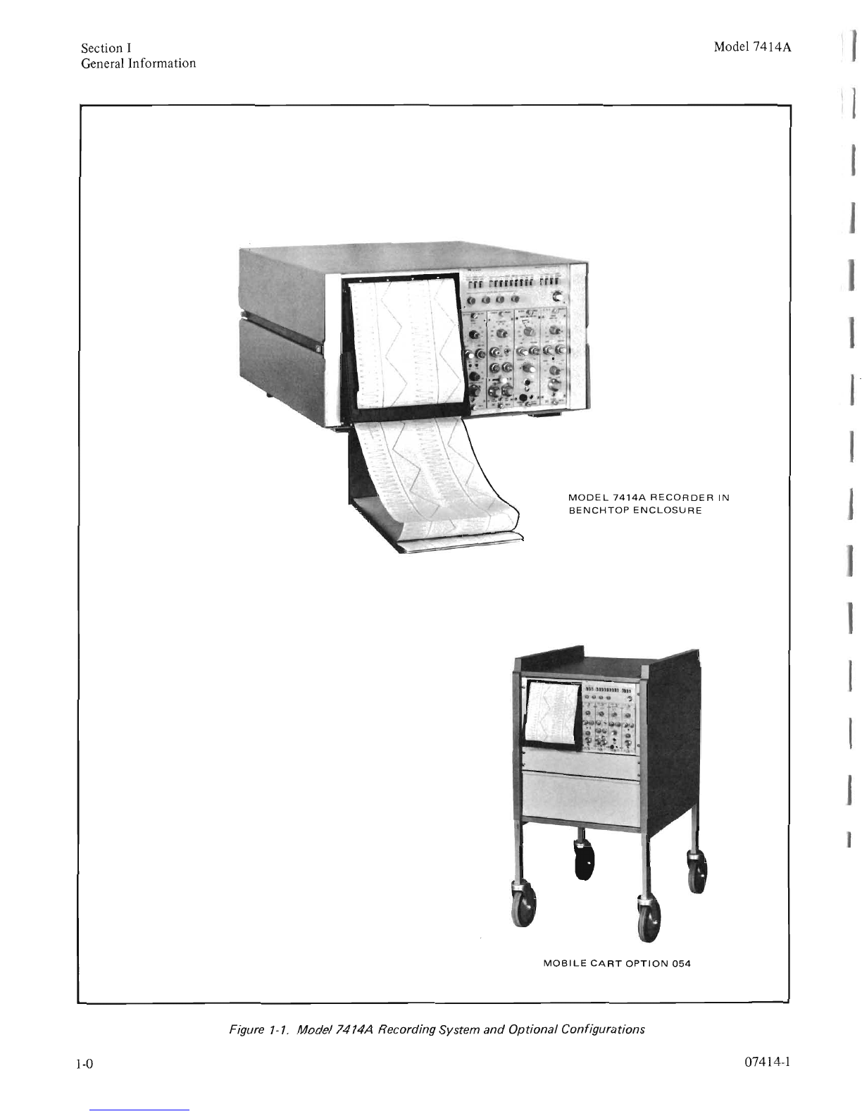
1-4. The Model 7414A Recorder (Figure 1-1)
at
the core
of
the system,
is
supplied
mounted
in a
benchtop
enclosure.
It
is
optionally available
mounted
in
amobile cart, or
unenclosed, for mounting in an existing
equipment
rack.
1-5. The Recorder houses
up
to
four Hewlett-Packard
8800
Series Preamplifiers and supplies
them
with operating
power and signal connections. The preamplifiers, selected
for each channel and ordered separately, are installed and
tested with the recorder
at
the factory.
It
is
easy
to
change
the function
of
any channel
by
loosening two front panel
thumbscrews and replacing the preamplifier with adifferent
model.
1-6. The Model
7414A
Recording System records signals
monitored from devices, processes, or transducers. To
monitor
asignal, connect the signal cable to the
input
connector for the assigned channel
on
the recorder rear
panel. The rear panel inputs are connected
to
signal condi-
tioning preamplifiers
mounted
in
the recorder. Each pre-
amplifier
output
is
applied to apower amplifier
that
drives
one recording stylus.
From
the preamplifier
output
on,
all
four channels are identical.
For
ease
of
maintenance, all
electrical adjustments are accessible from the front or top
of
the recorder, and most assemblies can be removed with
the recorder
mounted
in the enclosure, mobile cart, or
equipment
rack.
1-7. The recorder uses Z-fold chart paper for convenient
access to any
part
of
the recording. The folded paper
permits rapid scanning
of
the record
to
assess response
trends. All pages are numbered to allow insertion in a
notebook,
or
the complete record may be filed in the
original flat
box
(pages are 8 x 12 inches,
20
x
30
cm,
approximately). Anew pack
of
chart paper can be loaded
quickly, in less
than
ten
seconds,
to
minimize loss
of
recording continuity.
07414-1
1-8. The recorder may be remotely controlled to mark
events, start, or go on standby. Two event markers are
provided; one permits the user to indicate the start and
finish
of
an event, the second provides time interval
marking in minutes
or
seconds.
1-9. Applications
and
Specifications.
1-10. Awide selection
of
transducers and Hewlett-Packard
preamplifiers are available for research, laboratory, and
industrial applications. The following list gives some typical
applications where data can be measured, monitored, and
recorded using the recorder and Hewlett-Packard preampli-
fiers:
Engine Testing
Aircraft, Missile, and Space Flight Analysis
Seismographic Studies
Environmental Pollution Monitoring
Telemetry Systems
Production Control
Relative Displacement and Velocity Monitoring
1-11. Hewlett-Packard will be glad
to
cooperate in the
selection
of
transducers and preamplifiers for any particular
measurement, and to send you information
as
additional
instruments are developed
to
provide
your
recording system
with
other
capabilities.
For
help in expanding
your
system,
contact the field engineer
at
any Hewlett-Packard Sales/
Service Office listed in the
back
of
this manual.
1-12. Table
1-1
gives the specifications for the Model
7754A Recorder, a
part
of
the Model
7414A
Thermal Tip
Recording System, and Table
1-2
lists the recorder options
available. Preamplifier specifications will be found in the
separate preamplifier manuals. Preamplifier frequency
response and rise time
must
be modified by the frequency
response and rise time specifications given for the recorder.
Recording quality
is
improved by the recorder's low level
of
hysteresis distortion. Minor waveform details are
not
obscured by recorder-contributed distortion.
1-13. 8800 Series Preamplifiers
(7414A
System).
1-14. The
7414A
Recording System
is
factory assembled
for use with the solid-state
8800
Series Preamplifiers
(Figure 1-2). They plug in interchangeably from the front
of
the recorder. Signal connections are made
at
the rear,
but
signals can be monitored from the
front
of
the
preamplifiers. The general characteristics
of
each preampli-
fier are given in the following paragraphs.
For
complete
information see the preamplifier instruction manual.
1-1

Section I
General Information
Table 1-1. Model 7414A Recording System Specifications (7754A Recorder)
Model 7414A
1-2
SENSITIVITY: ±2.5 volts (±0.5 volts) full scale.
(Adjustable.)
FREQUENCY RESPONSE: Flat within ±0.5
dB
(±6%), dc to
50
Hz, reference 50 div. at 10 Hz; down
less
than 3
dB
at 100 Hz, reference 10 div. at 10 Hz.
POWER
RESPONSE: At 50
Hz:
More than 50 divi-
sions (full scale). At 100 Hz: More than 10 divisions.
CHART SPEEDS:
0.25,0.5,1.0,2.5,10,25,50,
and
100 mm/sec. Speed Regulation:
±1
%.
Paper
Weave:
Less
than 0.5 mm. (Speeds selected
via
panel push-
buttons.)
INPUT IMPEDANCE: Loading at preamplifier out-
put
is
50 kilohms, min.
NOISE: Not discernible with recorder input open or
shorted.
GAIN
STABILITY:
(One hour warmup). Tempera-
ture: 0.25 div/25°C, from 20°C to 40°C. Line Volt-
age:
0.25 divisions from 103 to 127 vac.
ZERO
DRIFT:
(One hour warmup, input shorted).
Temperature: 0.25 div/25°C, from 20°C to 40°C.
Line Voltage: 0.25 divisions from 103
to
127 vac.
OUTPUT
LINEARITY:
Error
less
than ±0.25
divi-
sions at any scale point, including hysteresis (after
calibration at center scale and at +20 divisions).
With 8808A Log-Audio Preamplifier, error
less
than
0.5 division at any scale point, including hysteresis
(after calibration for zero error at upper and lower
scale ends).
RISE TIME: 5milliseconds over any 20 divisions
(10% to 90%), overshoot adjusted for
4%
or less.
LIMITING:
Stylus limit
1.5
mm over channel edge
(adjustable).
MARKERS: Event: Local or remote control (mono-
polar), located on right side, between channels 3and
4. Timed: 1minute or 1second interval (monopolar),
located on left side, between channels 1and 2.
HYSTER
ES
IS:
Less than ±0.15 divisions (see line-
arity).
DAMPING: Galvanometer damping set
to
about
4%
overshoot.
CHART PAPER: Four
40
mm wide channels, each
with 50 divisions; time lines every 1mm; heat
sensitive Z-fold Permapaper ®with green grid lines
is
available in packs
of
500 sheets, each sheet 12 inches
(30 cm) long, and numbered for footage and index-
ing.
Green grid lines and black stylus trace make recording
suitable for reproduction.
PAPER
LOADING:
No threading required. Loading
in 10 seconds.
PAPE
R
TAKE
UP:
On shelf
of
recorder, or in drawer
provided with cart installations.
TRACE WIDTH: 0.020 inches (0.5 mm) nominal;
depends upon heat control setting.
REMOTE OPERATION: Rear panel connector J8:
Remote operation
of
chart drive, event marker,
optional extra marker. Connector also supplies ±12,
±20, and -24 vdc.
FRONT PANEL CONTROLS: Power, Chart Drive,
Chart Speed selection, Time Marker, Event Marker,
Channel Heat controls.
OTHER CONTROLS: Each Channel: Position, Gain,
Damping, High Limit, Low Limit,
440
Hz
Oscillator
Amplitude.
POWER
REQUIRED: 115/230 volts ac, (±10%), 60
Hz
(50
Hz
optional), 300 watts. Warmup time,
ap-
proximately
15
seconds.
DIMENSIONS: Height: 10.5 inches (29 cm). Width:
19.0 inches (48.3 cm), for standard rack. Depth:
22.75 inches (57.3 cm). Projection: 2.5 inches (6.3
cm) from rack front.
Bench
Top
Enclosure: Height: 11.87 inches (30.2
cm). Width: 20.25 inches (51 cm). Depth: 24 inches
(60.5 cm). Paper Takeup Tray projects 10.5 inches
(26.4 cm) from front; hangs down 5.5 inches (13.8
cm).
Mobile
Cart
(Option
054): Height:
41
inches (105
cm). Width: 23 inches (59 cm). Depth:
31
inches (79
cm).
WEIGHT: Recorder: 76
Ibs
(34.4 kg). Bench Top
Enclosure:
94
Ibs
(42.5 kg); with paper takeup shelf
95.5 Ibs (43.3 kg); with Mobile Cart: 1911bs (81 kg).
ENVIRONMENT: Maximum ambient temperature
(free air circulation): 40°C (104°F). No free air
cir~ulation:
25°C (77°F). Location: Free from dust,
explosive vapors, corrosive vapors, and extreme cold.
07414-1
I

Model 7414A
Option
001
008
012
015
054
Part
Number
7414A
07754-60600
07754-60350
Section I
General Information
Table
1-2. Model 7414A Recording System, Equipment Options
Description
Four Channel Thermal Tip Recording System, 60 Hz, 115/230V ac; mint gray front
panels, jade green knobs, 440
Hz
Oscillator for 8803A High Gain Preamplifier, and
2400
Hz
Oscillator for 8805A Carrier Preamplifier; moss gray Bench Top Enclosure
07754-60261.
Rack mounting kit (Figure 2-7), with paper take-up tray and panel.
For 115/230V ac, 50
Hz
operation.
Less one channel; right channel No. 4
is
deleted, event marker installed between
channels 2and 3, extra marker cannot be installed with this option.
Extra monopolar marker installed between channels 2and 3; this marker cannot be
installed with Option 012.
Mounted in 1064B Mobile Cart; moss gray, with paper take-up drawer, blank panel.
Note: For acomplete System, order up to four 8800 Series Preamplifiers.
Figure 1-2.
8800
Series Preamplifiers
07414-1
1-3

Section I
General Information
1-15. MODEL 8801A
LOW
GAIN
DC
PREAMPLIFIER.-
With amaximum sensitivity
of
5mV/div, the 8801A
provides stable and precise amplification from dc to the
limit
of
the recorder's capability, or up to
10kHz
when
used with an oscilloscope or other indicator. The 8801A
features calibrated zero suppression with limits
of
±10 and
±100 volts.
1-16.
MODEL
8802A
MEDIUM GAIN
DC
PRE-
AMPLIFIER. -The 8802A has again
that
is
five
times
greater than the 8801A and zero suppression to
±2
and ±20
volts. Except for the common-mode tolerance, which
is
smaller by afactor
of
five on the high sensitivity positions
of
the RANGE control, the choice between the 8801A and
8802A depends directly
on
signal input requirements.
1-17. MODEL 8803A
LOW
LEVEL PREAMPLIFIER. -
With amaximum sensitivity
of
1IlV/div, corresponding to a
gain
of
100,000, the 8803A accommodates amuch wider
rqnge
of
signal amplitude (within abandwidth
of
dc to 100
Hz) than the 8801A and 8802A. The 8803A features a
fully-guarded input circuit, with afloating input and
common-mode rejection
as
high
as
160
dB
at dc (120
dB
at
60
Hz).
In addition to ahigh rejection ratio, the input
circuit will tolerate acommon-mode voltage
as
high
as
±300
Vdc at any position
of
the RANGE control. Calibrated zero
suppression
is
provided in three maximum ranges: ±1, ±10,
and ±I00 volts with resolution to
10-
3.
1-18. MODELS 8805A/B CARRIER AMPLIFIER. -The
8805s measure any physical variable
that
can be coupled to
asuitable transducer, i.e., strain
gage
bridge, resistance or
reactance transducer, or differential transformer. Apartial
listing
of
physical variables includes: strain, pressure, force,
velocity, flow and acceleration. A2400
Hz
oscillator in the
recording system provides an excitation voltage which
is
amplified by abuffer amplifier in the 8805 to apower level
appropriate for exciting the external transducer, eliminating
the need for an external excitation circuit. The excitation
voltage, 5Vrms at 2400 Hz, can drive aload resistance
greater than 100 ohms; the amplifier will operate with
sources having
an
internal impedance
up
to
5000
ohms
at
the signal
input
terminals. Calibrated zero suppression
permits analyzing small signals when large static loads are
present on the transducer. Acalibration factor control
allows attenuation and zero suppression to be calibrated in
terms
of
transducer load units.
1-19.
MODEL 8806B PHASE-SENSITIVE DEMODU-
LATOR. -The 8806B provides adc
output
proportional
1-4
Model 7414A
to the rms value
of
an input signal component that
is
in
phase,
or
1800
out
of
phase with respect to an external
ac
reference voltage. For flexibility, the phase-reference volt-
age
can be shifted to any phase angle by three plug-in
calibrated phase shifters, available for frequencies
of
60,
400,
or
5000 Hz. Afourth plug-in phase shifter covers six
frequency bands from 50
Hz
to 40 kHz and provides for
continuous phase shifting from 00to 3600•Other features
include transformer isolation for
both
the signal and refer-
ence voltage circuits, and amaximum calibrated sensitivity
of
0.5 mV rms/div, corresponding to again
of
200 (rms ac
to dc).
1-20. MODEL 8807A
AC
TO
DC
CONVERTER. -The
8807Aprovides adc voltage
output
proportional to the
average value
of
afull-wave rectified ac input signal. Range
sensitivity
is
calibrated in terms
of
rms, for sinusoidal
waveforms. The
input
circuit
is
transformer coupled, float-
ing, and guarded for high common-mode rejection, allowing
measurements over awide range
of
input signal conditions:
3mV to 500 Vrms, from 50
Hz
to 100 kHz. Calibrated
zero suppression and variable scale expansion permit clear
analysis
of
small excursions in large
input
signals.
1-21. MODEL 8808A LOG LEVEL PREAMPLIFIER. -
The 8808A contains compression and full-wave detection
circuits
that
provide an
output
proportional to the
log}
0
of
the ac
input
signal amplitude, expressed in decibels, where
zero decibels
is
taken
as
a 1 volt rms sine-wave input
voltage. The unit provides for 50
dB
and 100
dB
ranges,
with full-span outputs corresponding to ±2.5 volts or 0to
+5
volts.
Input
signals from 3
mv
to
300
Vrms may be
recorded without changing ranges; avoltage ratio
of
100,000 (100 dB).
1-22. MODEL 8809A SIGNAL COUPLER. -The 8809A
is
alow cost, solid state preamplifier with selectable high or
low
input
impedance and aGAIN control.
It
is
used for
simple signal coupling
to
an
HP
direct writing recorder, in
single and multichannel systems.
1-23. Accessories.
1-24. For alist
of
recorder accessories, refer to Table 6-1,
Assembly A19, Accessories. Order accessories by their
individual part numbers. For other system accessories, refer
to the separate equipment manuals provided with the
recording system.
07414-1
I

Model 7414A
2-1.
INITIAL
INSPECTION.
SECTION II
INSTALLATION
2-11.
INSTALLATION.
Section II
Installation
I I
I
2-2. Initial inspection consists
of
acheck for physical
damage incurred during shipping,
and
the
completion
of
all
performance tests. See Figure
2-1
for
Recorder
inspection
particulars.
2-3. Mechanical Check.
24.
If
damage
to
the
shipping
carton
is
evident,
notify
the
HP
Sales/Service Office and
unpack
the
equipment
in the
presence
of
the
carrier's agent. Upon unpacking, inspect the
instrument
for mechanical damage such as scratches, dents,
broken
knobs,
or
other
defects. Also
check
the cushioning
maieri'!
ls
for signs
of
severe stress during handling.
2-5. Performance Tests.
2-6. The electrical
and
mechanical performance
of
the
Model 7414A Thermal Tip Recording System
may
be
verified
upon
receipt, using
performance
tests described in
Section V, Maintenance. An 8800-Series Preamplifier
must
be in place for these tests.
2-7. Damage Claims.
2-8.
If
the
instrument
is
damaged
in
transit,
notify
the
carrier
and
the
nearest Hewlett-Packard Sales/Service Office
immediately.
For
your
convenience, alist
of
these offices
is
located in
the
rear
of
this manual. Keep
the
shipping
carton
and packaging material for the carrier's inspection. The
Sales/Service Office will arrange for repair or replacement
of
the
System
without
waiting for claim
settlements
from
the
carrier.
2-9. STORAGE.
2-10.
If
the
Recording System
is
to
be
stored
for aperiod
of
time, wrap the
front
panels in protective padding and
seal
the
equipment
in a
moisture-proof
covering. Repackage
the System in a
container
similar
to
the original factory
carton.
If
the
System
is
installed in aBench
Top
Enclosure,
leave it
mounted
in the enclosure.
If
it
is
installed in a
Mobile Cart
or
equipment
rack, remove it from the
cart
or
rack
to
facilitate
moistureproof
packaging.
If
long-term
storage
is
anticipated,
pull
the
paper
table
out
at
the Cart
drawer and
unlatch
it. This will prevent aflat
spot
from
developing
on
the
drive roller from the spring-loaded
pressu
re
rolle
r.
07414-1
2-12. Recording Systems installed in
the
Bench
Top
Enclo-
sure
do
not
require installation instructions.
For
access to
the Recorder, loosen
knobs
at
the
front
of
the case and
raise the
top
cover (see Figure 2-1).
If
the Recorder
is
installed in aMobile Cart, release
the
four front-panel
shipping screws
to
slide the Recorder
out
for receiving
inspection and
performance
checks (see Figure 2-1).
If
the
Recorder
is
installed in an existing
equipment
rack,
the
rack
slides
must
be installed before
mounting
the
Recorder
(Option
001).
2-13. Preamplifier Installation.
2-14. The Recording
System
is
shipped with all preampli-
fiers installed.
To
change apreamplifier,
perform
the
following steps.
a. Switch
off
Recorder
power.
b. Loosen
the
top
and
bottom
front
panel screws and
pull
the
preamplifier straight
ou
t.
c. Insert the
replacement
preamplifier
into
the channel
guide,
push
firmly
to
mate
connectors,
and tighten screws
at
the
top
and
bottom
of
the
front
panel.
2-15. Power Connections.
2-16. Check
that
the
power
line voltage
and
frequency
is
the same as
that
shown
on
the
Recorder
nameplate,
located
on
a
shelf
at
the
left
side
of
the
rear panel (see Figure 2-2).
Note locations
of
the
fuses.
2-17. When making
power
connections,
push
the
POWER
button
on
the
front
panel so
that
it
protrudes
and
a
Z-shaped line appears. Otherwise, the recorder will
start
when
the
power
cord
is
plugged in. Refer
to
Figure 2-3 and
perform
the
following steps for Mobile Cart
power
connec-
tions.
a.
Connect
a
ground
wire (as shown)
to
agood
earth
ground,
such
as
acold
water
pipe.
b. Check
that
the
paper
take-up drawer
is
grounded
with
a
strap,
and
that
the
recorder chassis
is
grounded
to
the
cart.
c. Plug
the
power
cord
connector
into
the
recorder
POWER INPUT
jack,
and
into
the
line receptacle
built
into
the cart.
d.
Connect
the
cart
power
cord to a3-wire line
outlet,
completing
the
power
connections.
2-1

Section n
Installation
REMOVE 2
SCREWS
FOR
ACCESS TO
RETAINING SCREWS
Model 7414A
TYPICAL
RETAINING
SCREWS
Press front slide locks to slide recorder back into cart or
cabinet.
WARNING:
DO
NOT
ACTUATE REAR SLIDE LOCKS
UNLESS RECORDER IS SUPPORTED FOR REMOVAL.
Press rear slide locks to slide recorder completely
out
of
retaining slides.
I
2-2
Figure 2-1. Recorder Access
for
Receiving Inspection
07414·1

Model
7414A
AUXILIARY
SIGNAL
DRIVER
AMPLIFIERS
r------===~======----------"
I~-====:::::c=====------..
Section II
Installation
J24
SIGNAL
INPUT
F3----~r-
......
F4
F5
FUSE
COMPLEMENT
Reference
Designator
J23 J22
Service
J21
J19 J18
J8
POWER
OUT/REMOTE
J16 J15
S4
F1
i-+;-'-F2
J5 POWER IN
Value
and
Type
F1
F2
F3
F4
F5
F6 (not shown)
AC Power, 115V Service
AC Power, 230V Service
Recorder, 115V Service
Recorder, 230V Service
+20V dc
-20V
dc
-24V
dc
2400
Hz
Oscillator (Option 004)
-20V
dc
supply -
See
Figure 6-7.
6A
3AT
2.5AT
1.25AT
3AT
3AT
3AT
100mAT
Figure 2-2. Recorder Rear Panel Connections and Fuse Locations
07414-
i
2-3

Figure 2-3. Recorder
and
Mobile
Cart Power Connections
Section II
Installation
CART
POWER CORD
TO
WALL
OUTLET
POWER
OUTLETS
BARE
COLD
WATER PIPE
OR
OTHER
EARTH
GROUND
RECORDER POWER
CORD
MOBILE
CART
GROUNDING
WIRE
DRAWER
GROUNDING
STRAP
Model
7414A
,
2-18. Signal Connections.
2-19.
For
signal connection information relative to the
individual preamplifiers, refer to the preamplifier instruc-
tion manuals. Also refer to Figure 2-4 for adescription
of
signal cable preparation for the 8800-Series Preamplifiers.
2-20. Tape System Connections.
2-21.
If
an instrumentation tape recorder
is
to
be used with
the Recording System, the addition
ofa
4681A
or a
4682A
2-4
Control Section
is
recommended. Connections for the
Recorder and
the
Control Sections are shown in Figure 2-5.
2-22. Remote Control and Marker Connections.
2-23. Aremote
control
and marker plug
is
supplied with
the Recorder
as
an accessory. To make remote control
connections for operating the Recorder and the Event
Marker, make the cable connections shown in Figure 2-6,
using the HP parts noted in the illustration.
07414-1
1

II
IIModel 7414A Section II
Installation
SIGNAL CONNECTOR PREPARATION
I
II
a.
Slide the prepared
end
of
the cable into
the
cable clamp and through the
connector
shell. Also slide the end
of
the
cable through the guard shield
extension, for guarded input circuits.
For
non-guarded
input
circuits,
remove and store the guard shield extension.
b.
Wire
the connector according to the diagram below, according
to
preamplifier
to
be used. For guarded
input
circuits, slide the guard shield
extension
into
place after soldering the signal leads
to
terminals Aand
B.
c.
Press the
connector
block carefully into the connector shell.
d. Insert the retaining ring.
e.
Tighten the cable screws.
f.
Check with an
ohmmeter
to determine
that
the cable shields are not
shorted to
the
connector
shell or
to
each
other.
Connector HP 1251-1895
GUARD
~
CABLE
SHIELD
I
CLAMP
~
~
,
ETAINER
~
RING
~~.~.
INSULATOR
\%i
,BLOCK
'"
GUARD
SHIELD
EXTENSION
SHELL
SIG+
.........
~---.
1/4
1/4 1/4
1/4
SHIELD
~
t
CONNECTION
Double-
---
Shield Cable
lq
HP
8120-0800
cO~'i:~~~I:;:
3/4
~
1-1/4
~
,-,
-
SIG
-
-+--+-L-.l..--~
SIG
-
-++-----,
SIG+
PREAMPLIFIER
MODEL
8803A
8806B
*
8807A
**
GUARDED CABLE PREPARATION
Single-
Shield Cable
HP
81
20-0718
NOTES:
!I
I
II
*1. Connect
Ref
voltage
to
pins Aand B
on
auxiliary
connector
of
the
power
supply. **
1.
AC
output
available
on
pin
C
of
aux
iliary
connector
of
the
power
supply.
2. DC
input
(8807A,
Opt
02) available
on
pins A
and
B
of
auxiliary
connector
of
the
power
supply.
2
SIG
-
-;'--H-'---~
S
IG
+
.....:....~----.
Double-
Shield Cable
HP
8120-0800
1/4
1/4 1/4
~M~,~IELO
~NECTION
1--
1-1/4
SIG
-.........
+-----,
SIG+
PREAMPLIFIER
MODEL
8801A
8802A
8808A
8809A
"NOTE:
NON-GUARDED
CABLE PREPARATION
Single-
Shield Cable
HP 8120-0718
II
I
I!
Single
conductor
sh
ielded cable can be used
by
connecting center
conductor
to
pin
Aand
shield
to
pin
B.
CARRIER
PREAMPLIFIER CABLE PREPARATION
II
PREAMPLIFIER
MODEL
8805A
8805B
HP
Transducers having 5-pin
AN
connectors (pin
pattern
0 )
use
I
nput
Adapter
14060B
for
sig-
nal
input
connections.
For
other
signal sources,
connect
the
input
signals
as
shown.
The
transducer
output
leads and transducer
excitation
leads
must
be
twisted
and enclosed in braided shielding.
II
Figure
24.
7414A System
Input
Cable Preparation
I
I
II
07414-1
2-5

Section III
Operation
345
Model
7414A
6
II
II
II
1.
RECORDER
POWER SWITCH: Press
to
apply
power; press
to
remove power. Back-lighted
with
power
applied.
2.8800-SERIES
PREAMPLIFIERS:
Refer
to
the
individual
instruction
manuals
for
control
infor-
mation.
3.
MODE
CONTROL
BUTTONS: Pressing
the
STDBY
button
holds
the
styli
of
all
channels
at
chart
center
during
Recorder
operation.
The
REMOTE
button
transfers
control
of
the
Recorder
"run
mode"
to
a
remote
location.
The
RUN
button
starts
the
chart
drive, applies
heat
to
the
styli
and
signals
to
the
recording circuits.
4.
SPEED
MM/SEC
CONTROL
BUTTONS: Nine
speed
selection
buttons
select
standard
chart
speeds
from
0.25
to
100
mm/second.
Button
remains depressed
to
indicate
selected
chart
speed.
5.
TIMER
BUTTONS:
The
OFF
button-turns
off
the
interval timing
marker.
The
SEC
button
selects
timing
marks
at
1-second intervals.
The
MIN
button
selects
timing
marks
at
1-minute
intervals.
The
EVENT
MARKER
button
applies a
marker
pulse
when
pressed,
to
mark events in
the
process
being
recorded.
6.
STYLUS
HEAT
CONTROLS:
Individual
controls
adjust
the
heat
at
each
stylus
tip,
and
thereby
the
trace
width.
More
stylus
heat
is
generally required
for
high-frequency signals
than
low-frequency
signals.
Once
adjusted,
stylus
heat
is
automatically
regulated
to
compensate
for
changes
in
chart
paper
speed.
7. PAPER
TAKEUP
DRAWER (CART):
The
takeup
drawer
pulls
out
to
receive used
chart
paper.
For
Bench
Top
Enclosure models, a
paper
takeup
shelf
is
provided. Install as
shown
in
Figure 3-2.
II
II
II
Ij
II
3-2
Figure 3-1. 7414A Recording System,
Control
Locations
07414-1
II
II

Model 7414A Section III
Operation
1.
UNWRAP
PAPER and remove cardboard. Make sure highest odd
number
is
on
top
of
pack. 2.
PULL
PAPER
TABLE
OUT
AT
BdTTOM.
3. LOWER
IT
SLOWLY.
It
must be
fully
horizontal.
4.
SLIDE
PAPER PACK
INTO
FEED
TRAY
while
compressing paper,
and
pulling
top
sheet
out.
6. CLOSE PAPER
TABLE,
pulling
down
slightly
on paper.
Press
table
in
firmly
so
it
locks in place.
Note
that
tab
on
takeup tray
catches
in
hole
on
case lip.
9. IF RECORDER IS IN A
CART
OR A
CABINET,
PULL
OUT
PAPER
TAKEUP
DRAWER.
Odd-numbered sheet should
be
first
into
drawer.
8.
IF
RECORDER
IS
IN ACASE, IN
TALL
TAKEUP
TRAY.
Note
that
an
odd-numb
red
sheet should b
first
onto
tray.
Figure 3-2. Paper Loading Procedure
07414-1
3-3
Table of contents
Other HP Recording Equipment manuals

HP
HP A4500A - VMEbus Single Board Computer 744... Manual

HP
HP StorageWorks Modular Smart Array 1000 cs User manual

HP
HP E2418A User manual

HP
HP E2444A User manual

HP
HP 98641A User manual

HP
HP E2466C User manual

HP
HP 82973A HP-IL User manual

HP
HP StorageWorks ESL E-Series Guide

HP
HP E2470A User manual

HP
HP 64653A User manual