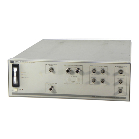
HP E2466C User manual

About this Manual
We’ve added this manual to the Agilent website in an effort to help you support
your product. This manual is the best copy we could find; it may be incomplete
or contain dated information. If we find a more recent copy in the future, we will
add it to the Agilent website.
Support for Your Product
Agilent no longer sells or supports this product. Our service centers may be able
to perform calibration if no repair parts are needed, but no other support from
Agilent is available. You will find any other available product information on the
Agilent Test & Measurement website, www.tm.agilent.com.
HP References in this Manual
This manual may contain references to HP or Hewlett-Packard. Please note that
Hewlett-Packard's former test and measurement, semiconductor products and
chemical analysis businesses are now part of Agilent Technologies. We have
made no changes to this manual copy. In other documentation, to reduce
potential confusion, the only change to product numbers and names has been in
the company name prefix: where a product number/name was HP XXXX the
current name/number is now Agilent XXXX. For example, model number
HP8648A is now model number Agilent 8648A.

User’s Guide
Publication number E2466-97006
First Edition, July 1997
For Safety information, Warranties, and Regulatory
information, see the pages behind Appendix A
© Copyright Hewlett-Packard Company 1997
All Rights Reserved
HP E2466C Preprocessor
Interface for the Intel
Pentium® II Processor

The HP E2466C Preprocessor
Interface—At a Glance
The HP E2466C Preprocessor Interface, when used together with the
HP 16505A Prototype Analyzer, provides a complete interface for state or
timing analysis between any Intel Pentium® II processor target system and
the HP logic analyzers listed below. The HP E2466C Preprocessor Interface
requires that the logic analyzer module is in an HP 16500B/C mainframe; the
HP 16505A Prototype Analyzer is also required.
The inverse assembler provides Pentium II processor assembly language
mnemonics and accurate instruction execution tracking of up to four
processors. The inverse assembler also supports Intel’s MMXTechnology.
The HP E2467A APIC Bus Preprocessor Interface can also be used with the
HP E2466C Preprocessor Interface to provide simultaneous bus analysis.
For instruction disassembly, Branch Trace Messagesmustbe enabledand
cachesmust bedisabled. Thisrequiresa Pentium IIprocessor run-control tool
(suchas theHP E3493A) anda 30-pin debug porton the target system.
Logic Analyzer 16500B
Software
Version
16500C
Software
Version
Channel
Count State
Speed Timing
Speed Memory
Depth
16550A (two card) v3.09 v1.03 204 100 MHz 250MHz 4 k states
16554A (three card) v3.13 v1.03 204 70 MHz 125MHz 500 k states
16555A (three card) v3.13 v1.03 204 110 MHz 250MHz 1 M states
16555D (three card) v3.13 v1.03 204 110 MHz 250MHz 2 M states
16556A (three card) v3.13 v1.03 204 100 MHz 200MHz 1 M states
16556D (three card) v3.13 v1.03 204 100 MHz 200MHz 2 M states
16500B/C Mainframe v3.13 v1.03
Additional Equipment Software Version
16505A Prototype Analyzer A.01.30
HP E3493A Processor
Probe v2.15 Provides Run Control connection to the target system. Refer the
HP
E3493A Processor Probe User’s Guide
for operating instructions.
ii Preprocessor Interface for the Pentium II Processor

The HP E2466C Preprocessor Interface consists of the configuration
software, for configuring the logic analyzer and the HP 16505A Prototype
Analyzer, and the preprocessor interface hardware, which connects to the
target system and processes the signals.
For more information on the supported logic analyzers, the HP 16505A, or
the microprocessor, refer to the appropriate reference manuals for those
products.
HP E2466C Preprocessor Interface
Pentium® II processor is a registered trademark of Intel Corporation.
MMXtechnology is a trademark of Intel Corporation.
Figure 1
Introduction
The HP E2466C Preprocessor Interface—At a Glance
Preprocessor Interface for the Pentium II Processor iii

In This Book
This book is the user’s guide for the HP E2466C Preprocessor Interface. It
assumes that you have a working knowledge of the logic analyzer used and
the microprocessor being analyzed.
This user’s guide is organized into three chapters and one appendix:
Chapter 1 explains how to set up and configure the preprocessor
interface and logic analyzer for state or timing analysis.
Chapter 2 provides reference information on the logic analyzer format
specification and symbols configured by the preprocessor interface
software, and information about the transaction tracker files. It also
contains information about the inverse assembler.
Chapter 3 contains reference information on the preprocessor
interface hardware, including the characteristics and signal mapping
for the preprocessor interface.
Appendix A contains information on troubleshooting problems or
difficulties which may occur with the preprocessor interface.
For more information on the logic analyzers or microprocessor, refer to the
appropriate reference manual for those products.
iv Preprocessor Interface for the Pentium II Processor

Contents
1 Setting Up the Preprocessor Interface
Before You Begin 1–3
Setting Up the Preprocessor Interface Hardware 1–5
To select the operating mode 1–5
To disassemble the S.E.C. cartridge 1–7
To connect to the target system 1–9
To connect to the HP 16550A two-card analyzer 1–13
To connect to the HP 16554/55/56 analyzers 1–14
To power up or power down 1–15
To protect the preprocessor interface when not in use 1–15
Setting Up the Preprocessor Interface Software 1–16
To copy the HP 16500B/C logic analyzer files 1–17
To load the HP 16505A Prototype Analyzer files 1–18
To set up the preprocessor interface for timing 1–19
To connect to the APIC and JTAG signals 1–20
2 Analyzing the Intel Pentium II Processor
Displaying Information 2–3
To set up the HP 16505A workspace 2–3
To display the format specification 2–3
To display the configuration symbols 2–4
To display captured state information 2–8
To display captured timing data 2–9
Using the Transaction Tracker 2–10
Transaction Tracker Messages 2–12
Errors and warnings 2–12
Reaching boundaries 2–12
Protocol Violations 2–13
Preprocessor Interface for the Pentium II Processor v

Using the Inverse Assembler 2–14
Hardware switches 2–14
Pentium II filter dialog 2–15
Pentium II preferences dialog 2–16
Disassembly 2–16
Transactions 2–16
Analysis techniques 2–18
Suggested Settings 2–18
Disassembler Behavior 2–19
Physical vs. Linear Addresses 2–19
Reset Configuration Information 2–20
Triggering Hints 2–21
Storage Qualification 2–21
Triggering on address and transaction type 2–21
Triggering on data and transaction type 2–21
3 Preprocessor Interface Hardware Reference
Operating Characteristics 3–3
Signal line loading 3–5
Modes of operation 3–6
State Mode Operation 3–6
State Mode Clocking 3–6
Timing Mode Operation 3–7
HP E2466C Block Diagram 3–8
Signal-to-Connector Mapping 3–9
Circuit Board Dimensions 3–21
Repair Strategy 3–23
A If You Have a Problem
Analyzer Problems A–3
Intermittent data errors A–3
No activity on activity indicators A–4
No trace list display A–4
Contents
vi Preprocessor Interface for the Pentium II Processor

Preprocessor Problems A–5
Target system will not boot up A–5
Erratic trace measurements A–6
Capacitive loading A–6
Transaction Tracker/Inverse Assembler Problems A–7
No transaction tracking or incorrect transaction tracking A–7
Transaction tracker/inverse assembler will not load or run A–8
Transaction tracker/inverse assembler errors and warnings A–8
******** ******** (no data displayed in the transaction display) A–8
? (appears next to a disassembled instruction) A–8
<ia notice: long format requires Intel NDA> A–9
<ia notice: non-ReqA info requires Intel NDA> A–9
<pp error: h/w in timing mode or clk qual off> A–9
<pp error: sync lost -- reset target> A–9
<pp error: rcnt invalid -- reset target> A–9
<pp error: scnt invalid -- reset target> A–9
<ia error: BTM with target code read missing> A–9
<ia warning: too few states -- modes assumed> A–10
<ia warning: next BTM missing -- no disassembly> A–10
<ia warning: disassembly requires Branch Trace> A–10
<data ECC error: ... > A–10
Intermodule Measurement Problems A–11
An event wasn’t captured by one of the modules A–11
Logic Analyzer Messages A–12
“. . . Inverse Assembler Not Found” A–12
“Measurement Initialization Error” A–12
“No Configuration File Loaded” A–12
“Selected File is Incompatible” A–13
“Slow or Missing Clock” A–13
“Time from Arm Greater Than 41.93 ms” A–14
“Waiting for Trigger” A–14
Contents
Preprocessor Interface for the Pentium II Processor vii

Figures
Figure 1. HP E2466C Preprocessor Interface 1–iii
Figure 2. Switches for State/Timing Mode and Clock Qualifier 1–6
Figure 3. Removing the S.E.C. Cartridge 1–7
Figure 4. Disassembling the S.E.C. Cartridge 1–8
Figure 5. Probe Connection Overview 1–9
Figure 6. Aligning the Probe End 1–10
Figure 7. Securing the Preprocessor Connection 1–11
Figure 8. Preprocessor Connector Numbers and Pin A1 Location 1–12
Figure 9. Configuration Menu with Timing Mode 1–19
Figure 10. Pin locations for APIC and JTAG signals 1–21
Figure 11. Logic Analyzer Format Specification 2–4
Figure 12. Logic Analyzer Listing Display 2–8
Figure 13. Logic Analyzer Waveform Display 2–9
Figure 14. Listing Display with Boundary Error Message 2–12
Figure 15. Listing Menu Showing End of Boundary 2–13
Figure 16. HP 16505A Pentium II Filter Dialog 2–15
Figure 17. HP 16505A Pentium II Preferences Dialog 2–17
Figure 18. HP 16505A Listing window for Software Analysis 2–18
Figure 19. Reset Configuration 2–20
Figure 20. Signal Line Loading 3–5
Figure 21. HP E2466C Block Diagram 3–8
Figure 22. HP E2466C Dimensions 3–21
Tables
Table 1. LED Indicators for Operating Mode 1–6
Table 2. Pin locations for APIC and JTAG signals (J5 and J6 are reserved)
1–21
Table 3. Signal/Label List 2–5
Table 4. Pentium II Processor Transaction Type Symbols 2–7
Table 5. Reset Configuration 2–20
Table 6. Operating Characteristics 3–3
Table 7. Product Regulations 3–4
Table 8. CMOS Inputs 3–5
Table 9. Pentium II Processor Signal List 3–10
Table 10. Replaceable Parts 3–23
Contents
viii Preprocessor Interface for the Pentium II Processor
1
Setting Up the Preprocessor
Interface

Setting Up the Preprocessor Interface
This chapter explains how to set up the HP E2466C Preprocessor
Interface hardware and software, configure the preprocessor, and
connect the preprocessor to supported logic analyzers. It also
contains information on setting up the HP 16505A Prototype Analyzer
for use with the HP E2466C Preprocessor Interface and using the
HP E2467A APIC Bus Preprocessor Interface.
1-2 Preprocessor Interface for the Pentium II Processor
Before You Begin
This section lists the logic analyzers supported by the HP E2466C, and
provides other information about the analyzers and the preprocessor.
Equipment Supplied
•The preprocessor interface circuit board.
•Cable, interposer, bottom clamp, and heat sink.
•The configuration files, for the logic analyzer and HP 16500B/C mainframe,
on a 3.5-inch disk. There are also Demo files for all supported logic
analyzers on the disk.
•Transaction tracker/inverse assembly software for the HP 16505A
Prototype Analyzer on a 3.5-inch disk.
•This User’s Guide.
Minimum Equipment Required
•The HP E2466C Preprocessor Interface, configuration files, and
transaction tracker software.
•An HP 16505A Prototype Analyzer.
•A target system with the microprocessor circuit board removed from the
S.E.C. cartridge. Detailed instructions for disassembling the S.E.C.
cartridge can be found in Intel’s S.E.C. Cartridge Disassembly
Application Note.
•One of the logic analyzers listed in the table on page ii, in an HP 16500B/C
Logic Analysis Mainframe.
For instruction disassembly, Branch Trace Messages must be enabled and
instruction cachesmust be disabled. Thisrequires a Pentium II processor
run-control tool such asthe HP E3493A, and a 30-pin debug port on the target
system. The HP E3493A run-control tool requires firmware version v2.15or
higher for the Pentium II processor.
Preprocessor Interface for the Pentium II Processor 1-3
Additional Capabilities/Equipment Required
For APIC Bus analysis, the HP E2467A APIC Bus Preprocessor Interface can
be used with the HP E2466C.
Additional configuration software for increased analysis of Pentium II
processor target systems is available with the appropriate Intel
non-disclosure forms. Contact your HP Sales Office for further information
about the restricted version.
Before You Begin
1-4 Preprocessor Interface for the Pentium II Processor
Setting Up the Preprocessor Interface
Hardware
Setting up for the preprocessor interface hardware consists of the following
major steps:
1Turn off the logic analyzer and the target system.
CAUTION To protect your equipment, remove the power from both the logic analyzer
and the target system before you make or break connections. Because the
logic analyzer supplies power to the preprocessor interface, the logic
analyzer should always be powered up before the target system; when
powering down, power down the target system first and then power down
the logic analyzer.
2Set the State/Timing Mode (Mode) switch and the
Compacted/Expanded Clock Qualifier switch according to the type of
analysis you wish to perform.
3Disassemble the S.E.C. cartridge containing the microprocessor.
4Install the preprocessor interface in the target system.
5Connect the logic analyzer pods to the cable connectors of the
preprocessor interface board.
To select the operating mode
Two switches on the preprocessor select the operating mode. The LEDs
indicate the selected mode (see table 1). The HP 16505A Prototype Analyzer
must also be updated to match the Mode (state or timing) selected by the
switches.
The MODE switch selects either State or Timing mode. In State mode, the
QUAL switch selects the clock qualifier to be either Compacted or Expanded.
The QUAL switch has no effect in timing mode.
The Expanded clock qualifier acquires a state for every bus clock when there
are transactions outstanding on the bus; no states are acquired when there
are zero outstanding transactions.
The Compacted clock qualifier maximizes the number of transactions
captured and is generally preferred.
Preprocessor Interface for the Pentium II Processor 1-5
Refer to Chapter 3, section "Modes of Operation", for more details on the
preprocessor operating modes and clock qualifiers.
Table 1. LEDIndicators for OperatingMode
LEDs Lit MODE
Switch QUAL
Switch Operating Mode/Clock Qualifier
Red only Up --- Timing
Red and Green Down Up State with Expanded Clock Qualifier
Green only Down Down State with Compacted Clock Qualifier
Switchesfor State/Timing Mode and Clock Qualifier
Figure 2
SettingUpthe Preprocessor Interface Hardware
To select the operating mode
1-6 Preprocessor Interface for the Pentium II Processor

To disassemble the S.E.C. cartridge
The S.E.C. cartridge consists of a thermal plate, skirt, cover, and
microprocessor card. The thermal plate, skirt, and cover must be removed to
access the processor card.
Detailed instructions for disassembling the S.E.C. cartridge can be obtained
from Intel. The following procedures are only intended as an overview.
Disassembling the S.E.C. cartridge voids the Intel warranty. Also, there is ahigh
probability that the cover and thermal plate will be damaged during
disassembly, and a small possibilitythat themicroprocessorcard will be
damaged. The S.E.C. cartridge isnot intended to be reassembledafter
disassembly.
1Remove the S.E.C. cartridge from the target system by pushing in the
two tabs on top of the cartridge, then pulling the cartridge up.
Removing the S.E.C. Cartridge
Figure 3
SettingUpthe Preprocessor Interface Hardware
To disassemblethe S.E.C. cartridge
Preprocessor Interface for the Pentium II Processor 1-7

2Using the instructions in the Intel S.E.C. Cartridge Disassembly
Application Note, insert a 1/8" small flat blade screwdriver between
the cover and the thermal plate, next to one of the four barbed posts
located at each corner of the thermal plate. Twist the screwdriver
until the barbed post pops free. Repeat this procedure for the other
barbed post at the same end of the cartridge, then repeat for the
other end of the cartridge.
Disassembling the S.E.C. Cartridge
3Using the instructions in the Intel S.E.C. Cartridge Disassembly
Application Note, use fine-tip round nose pliers to separate the tabs
on the thermal plate away from the locator pins. Remove the spring
retainer clips, then separate the thermal plate from the
microprocessor circuit board.
Figure 4
SettingUpthe Preprocessor Interface Hardware
To disassemble the S.E.C. cartridge
1-8 Preprocessor Interface for the Pentium II Processor

To connect to the target system
The probe end of the preprocessor connects directly to the microprocessor
on the target system.
1To prevent equipment damage, remove power from both the logic
analyzer and the target system.
CAUTION Serious damage to the target system or preprocessor interface can result
from incorrect connection. Note the position of pin A1 on the preprocessor
interposer and on the microprocessor before making any connection. Take
care to align the preprocessor connector assembly with the pins on the
microprocessor so that all pins make contact.
2Install the interposer onto the microprocessor on the target system.
The alignment tabs on the interposer aid in making proper alignment.
Ensure that pin A1 is oriented correctly (see figure below).
Probe Connection Overview
Figure 5
SettingUpthe Preprocessor Interface Hardware
To connecttothe target system
Preprocessor Interface for the Pentium II Processor 1-9

3Place the probe end of the preprocessor interface onto the interposer
using the three alignment pins as shown in the figure below.
Aligning the Probe End
Figure 6
SettingUpthe Preprocessor Interface Hardware
To connect to the target system
1-10 Preprocessor Interface for the Pentium II Processor

4Loosen the screw on the underside of the bottom clamp.
5Work the four clamp posts of the bottom clamp through holes in the
target system PC board. Slide the clamp on the probe end of the PC
board back, then work the four clamp posts on through the
preprocessor PC board.
Securing the Preprocessor Connection
6Move the top sliding clamp forward on the probe end until it holds
the clamp posts of the bottom clamp.
7Tighten the screw on the underside of the bottom clamp until it is
snug (80 inch-ounces of torque). If the screw is too loose, the
preprocessor will not make good contact with the microprocessor
pins. If the screw is too tight, it may damage the interface connector.
8Insert the heat sink into the rectangular opening on top of the
preprocessor interface. Select an orientation that does not interfere
with the target system. Tighten the two screws until the heat sink is
snug. Do not overtighten.
9Connect the heat sink to a +12 Volt power source. The black wire is
ground, and the yellow wire is positive. To protect your target
system and the preprocessor interface, ensure the fan is running
whenever the target system is powered.
Figure 7
SettingUpthe Preprocessor Interface Hardware
To connecttothe target system
Preprocessor Interface for the Pentium II Processor 1-11
Table of contents
Other HP Recording Equipment manuals

HP
HP 82973A HP-IL User manual

HP
HP 7750 User manual

HP
HP E2470A User manual

HP
HP E2444A User manual

HP
HP 64655A User manual

HP
HP MSM Series User manual

HP
HP StorageWorks ESL E-Series Guide

HP
HP 70907A Installation and operation manual

HP
HP 98641A User manual

HP
HP A4500A - VMEbus Single Board Computer 744... Manual