IDEAL 61-357 Use and care manual

Instrucciones en español adentro / Instructions en français à l’intérieur
61-357 Multimeter
61-347 Multimeter
Operation and Safety Manual
IDEAL®Test and Measurement

Introduction......................................................................3
Contacting IDEAL INDUSTRIES, INC .........................................3
Safety Information..............................................................4
Warnings..................................................................................................4-5
Cautions.......................................................................................................5
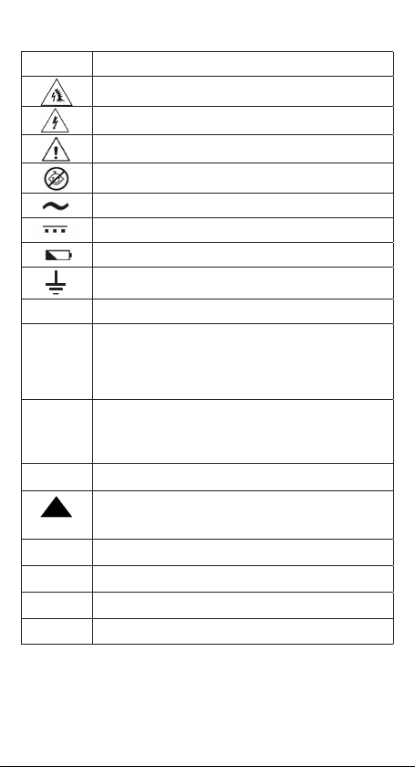
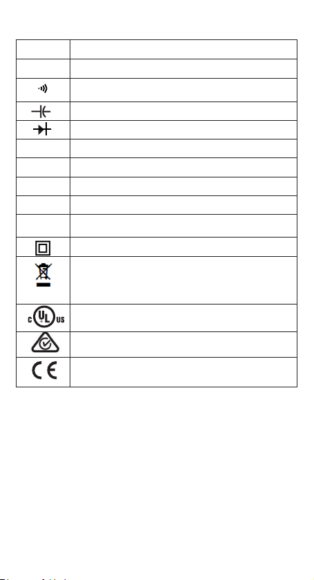
Symbols...................................................................................................6-7
Operation.....................................................................8-25
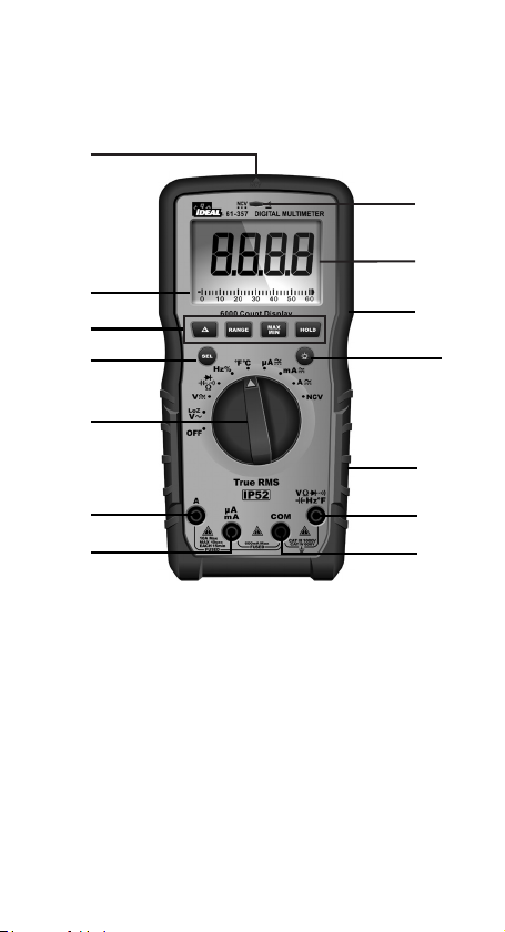
Identification and description of operating controls and
functions .................................................................................................8-9
Operating Features...............................................................................10-11
Using Test Leads........................................................................................12
Meter Operation ..................................................................................13-19
Non-Contact Voltage Testing..........................................................13
Lead Warning.................................................................................14
Fuse Warning.................................................................................14
SEL Button.....................................................................................14
Measuring Voltage.........................................................................15
Measuring Continuity ....................................................................16
Measuring Resistance....................................................................16
Measuring Capacitance..................................................................17
Measuring Diodes..........................................................................17
Measuring Frequency ....................................................................18
Measuring Temperature .................................................................18
Measuring Micro Amps .................................................................19
Measuring Milli Amps ...................................................................19
Measuring Amps............................................................................19
Functions Operation Table....................................................................20-21
Functions Indication Table ...................................................................22-23
Electrical Specifications .......................................................................24-25
Environmental Specifications............................................... 26
Mechanical Specifications .................................................. 26
EMC / EMI ...................................................................... 26
FCC ........................................................................... 27
Safety........................................................................... 27
Maintenance and Service ............................................... 27-28
Table of Contents
2

Introduction
The IDEAL®61-357 and 61-347 Digital Multimeters are auto ranging true root
mean square (TRMS) meters that measure AC and DC current (amps) in series via
test leads in the designated terminals, measures voltage, frequency, resistance,
continuity, capacitance, diodes via test-leads in the designated terminal and
measures temperature via a K-Type thermocouple. They also detect the presence
of voltage between 40V to 600V AC via a non-contact sensor in the top center of
the meter.
Contacting IDEAL INDUSTRIES, INC.
To contact IDEAL INDUSTRIES, INC., call one of the following telephone numbers:
IDEAL Industries USA Customer Service
• Phone Number: 800-435-0705
IDEAL Industries Canada Customer Service
• Phone Number: 905-683-3400
IDEAL Industries EMEA
• Phone Number: +44 (0)1925 444 446
IDEAL Industries Australia
• Phone Number: +61 3 9562 0175
Or visit the IDEAL Electrical Website at www.idealind.com
To register your product, find manuals, watch videos, simply scan this QR code.
3
Arc Flash and Shock Hazard, Proper PPE Required. Follow all safety procedures,
wear proper PPE in accordance to NFPA 70E. Read and fully understand the
instruction manual prior to using this product. Failure to comply can result in
serious injury or death.

Warning -Identifies conditions and actions that could result in
possible death or serious injury if the hazard is realized.
Caution - Identifies conditions and actions that could result in meter dam-
age, equipment under test damage or data loss if the hazard is realized.
WARNING
Safety Information
Arc Flash and Shock Hazard, Proper PPE Required. Follow all safety procedures,
wear proper PPE in accordance to NFPA 70E and follow the guidelines below and the
instructions in this manual when operating the meter. Failure to comply can result in
serious injury or death.
• Choking Hazard, Small Parts. Keep Away from Children. Sharp Objects
Hazard, This is not a toy. It is not for use or play by children. Keep Away from
Children. Failure to do so can result in serious injury.
• Only experienced or technically competent consumers should use this
equipment. When in doubt, call an experienced electrician to make any and all
necessary repairs or installations. At all times, perform any necessary work on
a de-energized circuit that has had its circuit breaker turned off and has been
locked out.
• Use the Meter only as specified in this manual or protection provided by the
Meter can be compromised.
• Before using or connecting the Meter, visually inspect it to ensure the cases
are not cracked and the back case is securely in place. Do not use if the Meter
appears damaged.
• Before using the test leads, inspect carefully for damaged insulation, exposed
metal or cracked probes. Check test leads for continuity. Do not use leads if they
appear damaged.
• Use only approved test leads. Do not use improvised connections that could
present a safety hazard.
• When using the probes, keep fingers behind the guard ring on the probes.
• Connect the common test lead before connecting the live test lead. When
disconnecting test leads, disconnect the live test lead first.
• This Meter is intended for use by qualified electricians. Follow NFPA 70E
Standards for Electrical Safety in the Workplace when using this Meter.
• Do not use without the batteries correctly in place and the battery door closed
and secured.
• Do not use Meter if it operates incorrectly as protection may be compromised.
When in doubt, have the Meter serviced.
• When servicing the Meter, use only specified replacement parts.
4

5
Arc Flash and Shock Hazard, Proper PPE Required. Follow all safety
procedures, wear proper PPE in accordance to NFPA 70E and follow
the guidelines below and the instructions in this manual when
operating the meter. Failure to comply can result in serious injury
or death.
• Have the Meter serviced only by qualified service personnel.
• Do not use the Meter around explosive gas, dust, or vapor, or during
electrical storms, or in wet environments.
• When measuring, keep fingers behind the Tactile Barrier. See “The Meter”
on pg. 8 and 9.
• Do not apply more than the rated voltage, as marked on the Meter, between
the terminals or between any terminal and earth ground.
• To avoid false readings that can lead to electrical shock and injury, replace
the batteries as soon as the low battery indicator ( ) appears.
• Remove the test leads from the circuit prior to removing the battery door.
• Voltages exceeding 30VAC or 60VDC pose a shock hazard so use caution.
• Always ensure that test leads are secured so that they cannot be accidentally
snagged or tripped over.
• Do not work alone so that assistance can be rendered in an emergency.
• Use extreme caution when working around bare conductors or bus bars.
Contact with the conductor could result in electric shock.
• Adhere to local and national safety codes. Individual protective equipment
must be used to prevent shock and arc blast injury where hazardous live
conductors are exposed.
• Disconnect circuit power and discharge all high-voltage capacitors before
you measure resistance, continuity, or capacitance.
• Never operate the Meter with the back cover removed or the case open.
• These meters are IP52 dust and water resistant. Following any contact with
water, thoroughly dry meter and test lead jacks prior to subsequent use.
• Cancer and Reproductive Harm - www.P65Warnings.ca.gov
Meter damage, equipment under test damage or data loss can occur
if the following guidelines are not adhered to.
• Use the proper terminals, function, and range for the measurement
application.
• Clean the case and accessories with a damp cloth and mild detergents only.
Do not use abrasives or solvents. Make sure the meter is completely dry
before use.
CAUTION
WARNING

Symbols & Descriptions
SYMBOL DESCRIPTION
Arc Flash and Shock Hazard
Shock Hazard
Warning or Caution
Choking Hazard
AC (Alternating Current)
DC (Direct Current)
Low Battery Indicator
Earth Ground
10 A Maximum Current Specification
CAT III IEC Measurement Category III
CAT III has protection against transients in equipment in fixed-
equipment installations such as distribution panels feeders,
and short branch circuits. Also included are lighting systems in
larger buildings.
CAT IV IEC Measurement Category IV
CAT IV has protection against transients from the primary
supply level such as a Meter or overhead or underground utility
service.
NCV Non-Contact Voltage Sensing
NCV Non-Contact Voltage Sensing Point
AAmperage AC and DC
Hz Frequency measured via the test leads
VVoltage AC or DC
Hz% Frequency displayed as % measured with AC Voltage
6

SYMBOL DESCRIPTION
ΩOhms
Continuity
Capacitance
Diode
°F °C Temperature Degrees Fahrenheit / Celsius
LCD Liquid Crystal Display
MAX/MIN Display MAX and MIN Measurement Variations
Range Auto or Manual Range Selection
∆Delta (Relative)
Double Insulation
Do not dispose of this product as unsorted municipal waste.
It must be properly disposed of in accordance with local
regulations. Please see www.epa.gov or www.erecycle.org for
additional information.
Conforms to applicable North American Safety Standards
Conforms to applicable Australian Safety Standards
Conforms to European Directives
Symbols & Descriptions
NOTE: The Measurement Category (CAT) and voltage rating of any combination
of test probe, test probe accessory, current clamp accessory, and the Meter is the
LOWEST rating of any individual component.
7

Identification and Description of Operating
Controls and Functions for the 61-347 and 61-357
Digital Multimeters:
1. HV, & Continuity LED
2. LCD Display
3. Tactile Barrier
4. Backlight Button
5. Rubber Boot
6. Volts/Ohms Input Terminal
7. Common (COM) Input Terminal
8. Mili Amps, Micro Amps Input Terminal
9. Amps Input Terminal
10. Measuring Functions Dial
11. Function Select Button
12. Function Buttons
13. NCV Sensing Point
14. Analog Bar Graph (61-357 only)
8
Operation

4
1
3
6
11
10
2
5
12
14
9
7
8
9
13

High Voltage Warning (HI-V)
The meter beeps once (for 1 second) and a red LED illuminates and remains on as
long as the voltage remains above 30V AC or DC, or when the meter’s voltage range
is exceeded.
NOTE: This feature does not work in the Ohm, capacitor, continuity or amperage
modes.
Data Hold Feature
Press the Hold button to toggle in and out of the data hold mode. “H” appears in the
upper left of the meter display when data hold is active. Use the data hold feature to
lock a measurement reading on the display. Press the Hold button again to unlock
the display and obtain a real-time reading.
MAX/MIN Feature
The MAX/MIN records the maximum and minimum measured value. Press the
MAX/MIN button to activate this feature and to toggle between MAX, and MIN
readings. The unit will continually capture MAX and MIN values over time.
Depressing the MAX/MIN button for >2 sec. exits the MAX/MIN mode.
NOTE: When the MAX/MIN function is activated, the Auto Power Off (APO) feature
will be disabled. When you exit the MAX/MIN function, Auto Power Off feature is
enabled.
REL Feature
A short press of the ‘ ’ button will activate or deactivate the REL function.
Range
The meter is auto ranging, however the user may select a specific range by pressing
the range button repeatedly.
Auto Power Off (APO) Feature Disable
The meter automatically powers itself down after about 30 minutes of no use. Press
any button, and the meter will wake up and display the last reading taken before
power down. To Disable APO, press and hold the SEL button while turning the dial
to any desired function. When APO is defeated, the “APO” will be removed from the
display. Turning the meter off and back on will restore the APO default.
Analog Bar Graph
An analog scale representation of the digital readout values. (61-357 only)
10
Operating Features

11
Press the Backlight button on the meter to turn the backlight on and off. The white
backlight will remain lit for about 5 minutes before it automatically turns off to
conserve battery power. Or turn the backlight off by pressing the button again.
Backlight
Backlight is selectable
to be on in all
functions.

WARNING: Arc Flash and Shock Hazard, Proper PPE Required.
Follow all safety procedures, wear proper PPE in accordance to NFPA 70E and
assure that the Protective Caps are in place when operating a properly rated
electrical meter/tester using the TL-757 Test Leads in a CAT IV 600V or CAT III
1000V environment.
This meter is intended for use with the IDEAL TL-757 lead set (provided with this
product) or equivalent. The lead set must comply with requirements for Overvoltage
and Measurement Categories CAT IV 600V CAT III 1000V.
12
Using Test Leads
WARNING: Arc Flash and Shock Hazard, Proper PPE Required.
Follow all safety procedures, wear proper PPE in accordance to NFPA 70E and
follow the guidelines below and the instructions in this manual when operating
the meter with TL-757 Test Leads or equivalent. Test Leads must be rated for the
electrical environment the meter is being used in and have a voltage rating of at
least the voltage of the circuit to be measured. Failure to comply can result in
serious injury or death.
• Choking Hazard, Small Parts. Keep Away from .....
Children. Sharp Objects Hazard, This is not a toy. It is not for use or play by
children. Failure to do so can result in serious injury or death.
• Use only approved test leads. Do not use improvised connections that could
present a safety hazard.
• Ensure that the test leads are inserted into the correct input jacks when
measuring AC or DC current.
• Prior to using the test leads, inspect them carefully for damaged insulation,
exposed metal or bent probes. Check test leads for continuity. Do not use
leads if they appear damaged.
• When using the probes, keep fingers behind the guard rings on the probes.
• Connect the common test lead before connecting the live test lead. When
disconnecting test leads, disconnect the live test lead first.
• Always ensure that test leads are secured so that they cannot be accidentally
snagged or tripped over.
• These meters are IP52 dust and water resistant. Following any contact with
water, thoroughly dry meter and test lead jacks prior to subsequent use.
Protective Cap Guard Ring
CAT III 1000V, CAT IV 600V (with cap on)
WARNING: To prevent possible electrical shock or personal injury, the
protective caps must be in place when operating a properly rated electrical meter/
tester using the TL-757 Test Leads in a CAT IV 600V or CAT III 1000V environment.

Meter Operation
13
Non-Contact Voltage Sensing
First, rotate the function key to the NCV position. Place the sensing point marked
with NCV close to an AC outlet (or any AC conductor such as light switches or
power cords) and scan back and forth across the outlet. The meter beeps On/Off
continuously and the Red NCV LED above the display flashes if the sensing antenna
detects live voltage greater than 40V AC (50 -60 Hz). Voltages with frequencies
higher than 60Hz or electrostatic charges may also be detected by the NCV sensing
antenna. To differentiate between hot and neutral in an outlet, place the NCV tab
directly next to each slot in the outlet. The tone (buzzer) will sound over the slot
that is energized and not on the neutral slot. Either test lead can also be used to
differentiate between the hot and neutral. Plug the red or black test lead into the
V input jack on the meter. With the function switch in the NCV position, insert the
probe end of just one probe into the slots on the outlet. The meter will beep and the
Red LED will flash when a hot conductor is contacted.
NOTE: While the NCV is a helpful function, it is ALWAYS
RECOMMENDED that the operator verify that any electrical conductor is
completely de-energized and that no voltage is present by measuring
for voltage AND CONFIRMING THAT NO VOLTAGE IS PRESENT and that
all applicable PPE and lock out tag out procedures be followed before
attempting any work on ANY electrical distribution system.

14
SEL Button
Lead Warning Fuse Warning
Lead Warning: When inserting the test
lead into any amperage input terminal, but
the rotary function switch IS NOT set to the
correct relative amperage position, the meter
will beep at 3Hz, LCD will display ”LEAd“
and “ .”, flashes at 3Hz. If any amperage
function is selected first, but the test lead IS
NOT in the relative amperage input jack,the
meter will also beep at 3Hz and the LCD will
display “LEAd” and “ .”, flashes at 3Hz.
Fuse Notification: The test leads
CANNOT be short circuited or used for
measuring while testing the fuse.
1. If the 600mA/1000V fuse is blown,
setting the rotary switch to the “mA”
or “uA” setting, the LCD will display
“FUSE” and “ .”, and the buzzer
will beep continuously at the same time.
2. If the 11A/1000V fuse is blown,
setting the rotary switch to the “A”
setting, the LCD will display “FUSE”
and “ .”, and the buzzer will beep
continuously at the same time.
The SEL Button allows the user to toggle between multiple
functions when the function dial is used to select a specific
function. This can include but is not limited to toggling between
degrees F and C, AC and DC voltage or current, continuity,
resistance, capacitance and diode measurements.

Measuring AC ( ) or DC ( ) Voltage
15
Lead Warning
*Note: When measuring AC voltage, Ghost or stray voltages (caused by
induced voltages coupling from one parallel conductor to the next as found when
measuring one conductor in multiple conductor circuits) may cause an incorrect
value. Selecting the Low impedance position (LoZ) on the dial, (see inset above)
while measuring voltage with the 61-357 will defeat the influence of Ghost or Stray
voltage.
AC V LoZ Setting* 61-357 Only
Caution - Use caution when using the LoZ function on equipment that may
be damaged by being connected to a low impedance source.
To assist with voltage readings, a bar graph will appear in the display.

16
Verifying Continuity ( )
• Verify the circuit is de-energized.
• The meter will sense the level of resistance and beep if the resistance is less
than 10 Ω’s to confirm that continuity is present.
• The red LED will illuminate and the resistance value will be displayed.
• The default setting is Continuity
• To exit Resistance and enter the Capacitance mode, press the SEL button.
• Verify the circuit is de-energized to obtain accurate measurements.
• To exit Continuity and enter the Resistance mode, press the SEL button.
Measuring Resistance (Ohms / Ω)

17
Verifying Continuity ( )
• To exit Resistance and enter the Capacitance mode, press the SEL button.
• To exit Capacitance and enter the Diode Test mode, press the SEL button.
• Verify the circuit is de-energized to obtain accurate measurements.
• To exit Continuity and enter the Resistance mode, press the SEL button.
Measuring Resistance (Ohms / Ω)
Measuring Capacitance ( )
Measuring Diodes ( )

Measuring Frequency ( Hz )
Measuring Temperature ( °F °C )
Hz using Voltage
For % Duty Cycle Press the
SEL button
Press SEL to toggle
between F and C
18

Measuring Frequency ( Hz )
Measuring Temperature ( °F °C )
Measuring Micro Amps (μA)
Measuring Milli Amps (mA)
Measuring Amps (A)
19
CAUTION
Meter damage. Measure current in
Micro Amps for a maximum duration
of 10 minutes. Failure to comply can
result in meter damage.
CAUTION
Meter damage. Measure current in
Milliamps for a maximum duration
of 1 minute. Failure to comply can
result in meter damage.
CAUTION
Meter damage. Measure current in
Amps for a maximum duration of 10
seconds. Failure to comply can result
in meter damage.

Button Response Default Function Operation
HOLD HOLD: All Functions Normal Measurement Short Press: Circularly enter or exit the data hold mode, LCD will display “ “ after enter
HOLD function.
SEL /
ACA / DCA DCA
1) Short press: Circularly select the relative measurement function.
2) When in HOLD, RANGE, MAX/MIN, REL function, Short press the SEL key to quit current
function and circularly change relative Select function.
ACV/DCV ACV
Hz/% Hz
/ Ω/ / Continuity
°F/°C °F
RANGE ACV, DCV, ACA, DCA, ΩAuto range (LCD display
“AUTO”)
1) Short press the RANGE key to enter manual range mode (LCD will not display “AUTO”), and
the current range, press again to enter cyclical selection range. Long press: exits manual range
and enters Auto range. Switching measurement setting or restarting the unit returns the unit to
the default setting.
2) In HOLD, MAX/MIN, REL function, Short press the RANGE key to exit the current function and
enter the relative range function.
MAX/MIN ACV, DCV, ACA, DCA,
Ω, °F/°C Normal Measurement
1) Short press: enter “MAX/MIN” statistics mode, continuously updates the data, and you can
circularly view the maximum value→ minimum value→ maximum value. Long press: exits
statistical mode and returns to the normal working mode. After pressing the REL key, and then
short pressing MAX/MIN, the unit will show the MAX/MIN after deducting the initial offset value.
2) When HOLD function is in use, MAX/MIN is invalid.
3) After entering the statistical mode, exit the automatic range at the same time and enter into
the current range, the APO will be disabled; exit the MAX/MIN function to restore the automatic
range and automatic shutdown.
4) In the statistical mode, a short press of the HOLD key will stop refreshing the statistical data.
At the same time, a short press of the MAX/MIN key can review the stored data of MAX/MIN, a
short press of the HOLD key exits HOLD to continue refreshing the statistical data.
: ACV, DCV, ACA, DCA,
CAP, Ω, °F/°C Normal Measurement
1) Short press: Circularly enter or exit REL function (when entering REL function, LCD will
display “ ” symbol )
2) Entering the REL function, exits auto range and enters into the current range.
3) Entering the REL measurement mode does not change the actual measurable range of the
current range
4) When HOLD or MAX/MIN is in use, REL function is invalid.
Non-Contact Voltage Indication Displays “EF” – Electromagnetic Field
Functions Operation Table
20
This manual suits for next models
1
Table of contents
Languages:
Other IDEAL Multimeter manuals

IDEAL
IDEAL SecuriTEST User manual

IDEAL
IDEAL ND 3511-1 User manual

IDEAL
IDEAL 61-797 User manual

IDEAL
IDEAL ND 2366-1 User manual

IDEAL
IDEAL 61-614 User manual

IDEAL
IDEAL 61-340 User manual

IDEAL
IDEAL ND 2350-1 User manual

IDEAL
IDEAL 61-327 Use and care manual

IDEAL
IDEAL ND 2365-1 User manual

IDEAL
IDEAL ND 4950-3 User manual
Popular Multimeter manuals by other brands

Steinberg Systems
Steinberg Systems SBS-DM-1000USB user manual

Fluke
Fluke 8062A instruction manual

Elenco Electronics
Elenco Electronics M-1006K Assembly and instruction manual

Control Applications
Control Applications ElNet VIP quick start guide

Rain Bird
Rain Bird TI-DSA500 operating instructions

RS
RS IDM 503 instruction manual