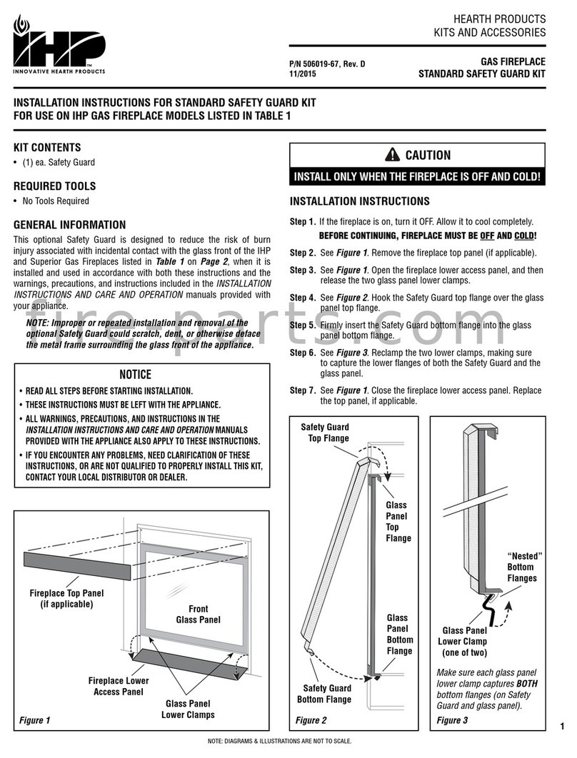
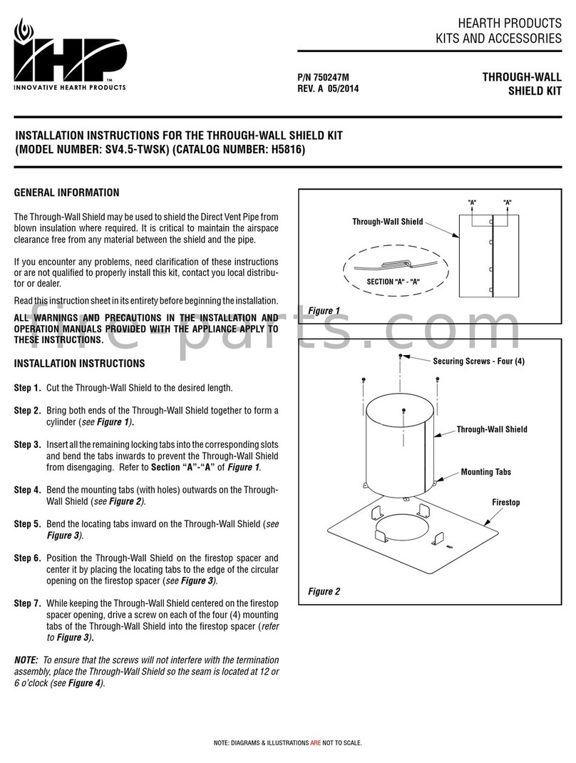
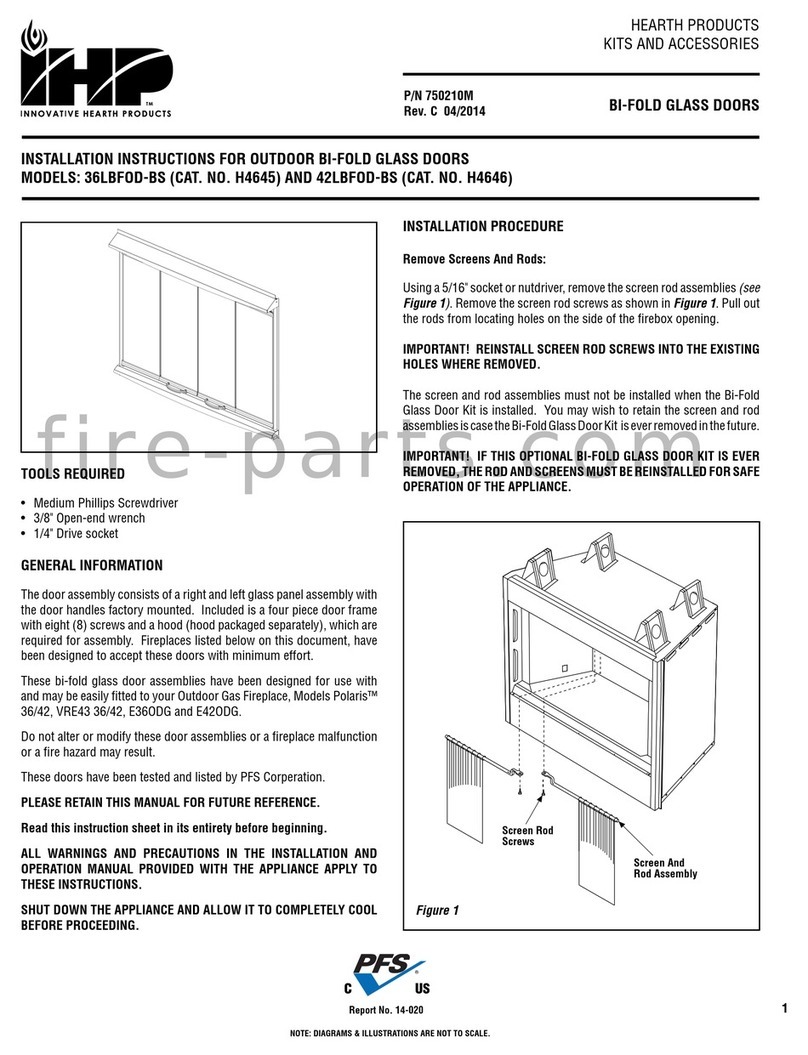
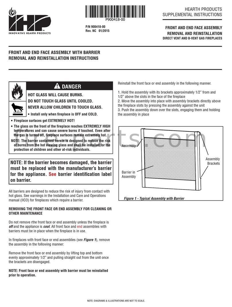
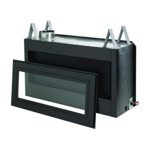
IHP HeatFlo Kit User manual

NOTE: DIAGRAMS & ILLUSTRATIONS NOT TO SCALE. 1
GENERAL INFORMATION
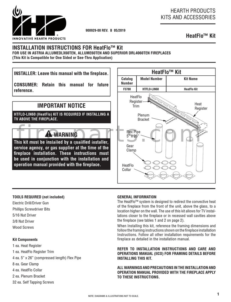
The HeatFlo™ system is designed to redirect the convective heat
of the fireplace from the front of the unit, above the glass, to
a location higher on the wall. The use of this kit allows for TV
installations closer to the fireplace or in recessed wall cavities
above the fireplace (see Tables 1 and 2, Page 3).
When Installing this kit, reference the framing dimensions and
follow the framing instructions shown on the fireplace installation
Instructions. Follow all other installation requirements for the
fireplace as detailed in the installation manual.
REFER TO INSTALLATION INSTRUCTIONS AND CARE AND
OPERATIONS MANUAL (IICO) FOR FRAMING DETAILS BEFORE
INSTALLING THIS KIT.
ALL WARNINGS AND PRECAUTIONS IN THE INSTALLATION AND
OPERATION MANUAL PROVIDED WITH THE FIREPLACE APPLY
TO THESE INSTRUCTIONS.
WARNING
This kit must be installed by a qualified installer,
service agency, or gas supplier at the time of the
fireplace installation. These instructions must
be used in conjunction with the installation and
operation manual provided with the fireplace.
INSTALLER: Leave this manual with the fireplace.
CONSUMER: Retain this manual for future
reference.
HeatFlo™ Kit
INSTALLATION INSTRUCTIONS FOR HEATFLO KITS
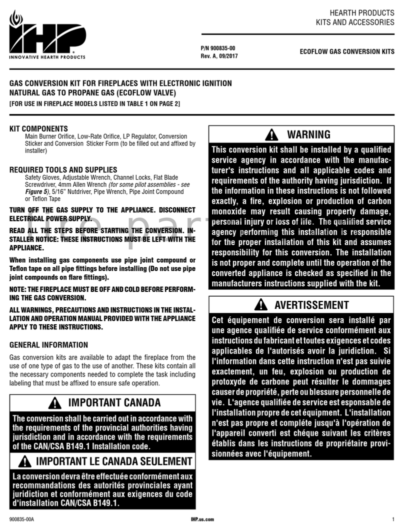
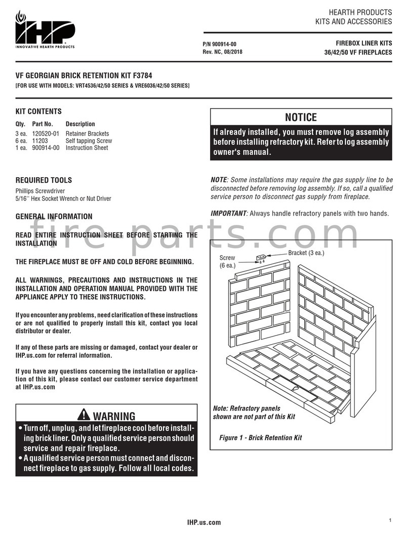
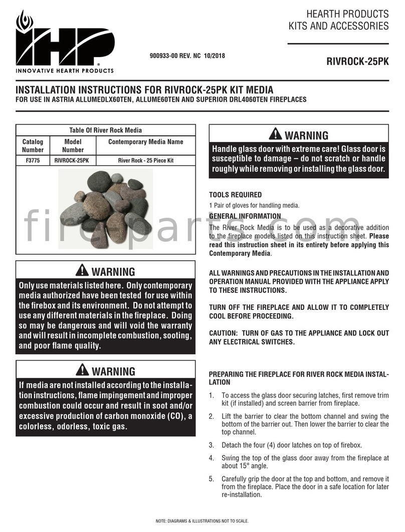
[FOR USE WITH MODELS: Compass45TEN, CompassDLX45TEN, Compass55TEN, CompassDLX55TEN, DRL2000 45/55 and DRL3500 45/55]
HEARTH PRODUCTS
KITS AND ACCESSORIES
P/N 901068-00
REV. A 07/2021
Figure 1 - Kit Contents Overview
KIT CONTENTS (see Figure 1)
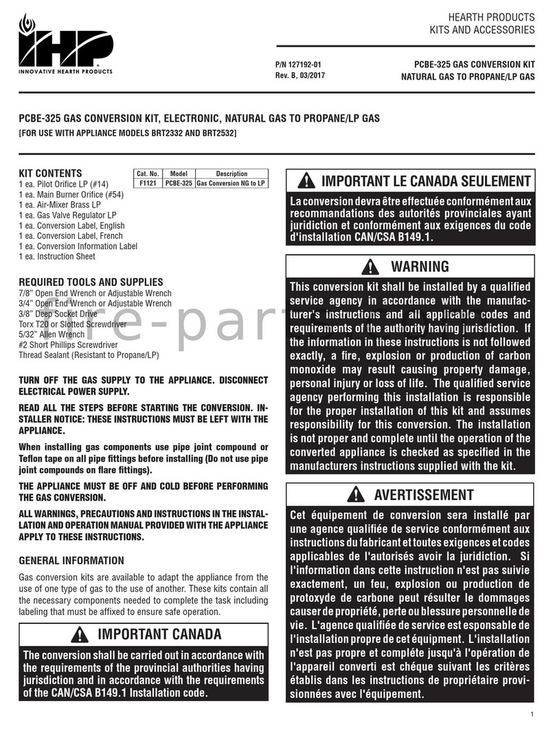
1 ea. Register Assembly
1 ea. Register Trim
4 ea. 4-1/2” x 24” Flex Pipe (stretches up to 70” in length)
8 ea. Gear Clamp
2 ea. Register Support Bracket
18 ea. Screws
4 ea. Collar Mounting Plate
4 ea. Small Collar
4 ea. Large Collar
1 ea. Hood
TOOLS / SUPPLIES REQUIRED (not included)
Electric Drill/Driver Gun
Phillips Screwdriver Bits
5/16 Nut Driver
3/8 Nut Driver
Wood Screws
HeatFlo™ Kit
Cat. No. Model Number Kit Name
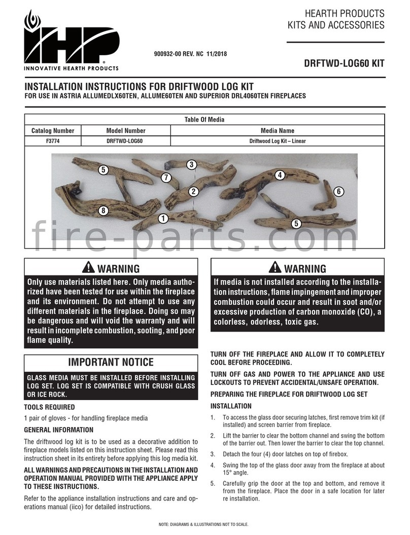
F4454 HTFLO-DV45 Kit, HeatFlo 45 DV Units
F4453 HTFLO-DV55 Kit, HeatFlo 55 DV Units
Register Trim Register Assembly Fireplace Hood
Collar Mounting
Plates
Large Collars
Gear Clamps
Small Collars
Flex Pipes
Register Support
Brackets
Figure 1

NOTE: DIAGRAMS & ILLUSTRATIONS NOT TO SCALE.
2
WARNING
Ensure clearances to combustibles are maintained when building a mantel or shelves above the fireplace.
Elevated temperatures on the wall or in the air above the fireplace can cause melting, discoloration or damage
to decorations, a television (TV) or other electronic components.
IMPORTANT NOTICE
Most television manufacturers instruct the homeowner to not place the television above a heat source. Doing so may
negatively affect the longevity of the television and may negate the warranty. If you do place a television above the
fireplace, please be aware of the large amount of heat generated by the fireplace and consider placing the television
above the fireplace at 12” minimum on a flush wall and at 18" for a recessed installation, to reduce the amount of heat
that reaches the television. The homeowner must understand that IHP does not take responsibility for any negative
impact to televisions placed near this fireplace.
FRAMING DIMENSIONS
Figure 2 - Fireplace Framing Dimensions For HeatFlo Installations - Flush Wall & Recessed Wall Pocket
Framing Dimensions - Inches (millimeters)
A B C D* E* F* G H
45” Models
45-7/8 (1165) 18 (458) 29 (737) 3-1/2 (89) 81-1/2 (2070) 1-1/2 (38) 43-1/2 (1105) 5-1/8 (130)
55” Models
55-7/8 (1420) 18 (458) 29 (737) 3-1/2 (89) 81-1/2 (2070) 1-1/2 (38) 53-1/2 (1359) 5-1/8 (130)
with HeatFlo Kit
forFlush Wall
with HeatFlo Kit
forRecessed Wall Pocket
E*
B
A
G
H
C
F*
F*
D
A
B
E*
G
H
C
with HeatFlo Kit
forFlush Wall
with HeatFlo Kit
forRecessed Wall Pocket
E*
B
A
G
H
C
F*
F*
D
A
B
E*
G
H
C
with HeatFlo Kit
for Flush Wall
with HeatFlo Kit
for Recessed Wall Pocket
NOTE: Unit must be installed a minimum of 6” off floor if the optional facade is to be installed.
D* Maximum allowable depth
E* Minimum height from appliance base to ceiling
F* Minimum distance from framed opening to ceiling

NOTE: DIAGRAMS & ILLUSTRATIONS NOT TO SCALE. 3
Table 1 - Minimum Dimensions for Television (TV) Installed
Above Fireplace (Flush Wall)
(A) TV Above fireplace Opening (Min.) 12” (305 mm)
(B) TV Below Heat Vent Opening (Min.) 3” (77 mm)
(C) Vent Opening Below Ceiling 4” (102 mm)
See Tables 1 and 2 for TVs Installed above the fireplace:
WIRING NOTE: If running wiring into the enclosure, use thermal insulating wrap around the wiring. Secure the wiring to protect from
contact with hot surfaces.
Television (TV)
Fireplace
Ceiling
Wall
Base of Fireplace
HeatFlo
Register
Opening
B
C
A
Min. 76”
(1930 mm)
Max. 20 ft.
(6.096 m)
Table 2 - Minimum Dimensions for Television (TV) Installed
Above Fireplace on a Recessed Wall Pocket
(A) Pocket Above Fireplace Opening (Min.) 18” (457 mm)
(B) Pocket Below Fireplace Opening (Min.) 5-1/2” (140 mm)
(C*) Vent Opening Below Ceiling 4” (102 mm)
* NOTE: Maximum pocket depth is 3-1/2” (89 mm)
Television (TV)
Fireplace
Ceiling
Wall
HeatFlo
Register
Opening
B
C
A
Min. 76”
(1.930 m)
Max. 20 ft.
(6.096 m)
3" Min.
(All Sides)
Pocket *
*
TVs should not be used in situations where the actual TV temperature exceeds the manufacturer’s technical specification. Contact
the TV manufacturer directly if you cannot locate this information or have questions regarding this information.
NOTE: Clearances to TV are provided only for guidance, please follow TV manufacturer’s recommendation for installation.
A
1-1/2”
4-1/2” DIA.
2-5/8”
1/2” FACING
3-1/2”
1”
6-1/4”
3-1/4”
3-1/4”
1”
B C
D
B
11”
Figure 2
Register and Trim Dimensions
Inches (millimeters)
A B C D
45” Models
42-7/8
(1089)
8
(203)
17
(432)
44-5/8
(1133)
55” Models
52-7/8
(1343)
12
(305)
20
(508)
54-5/8
(1387)
Base of Fireplace
Figure 3 - Register Assembly and Trim

NOTE: DIAGRAMS & ILLUSTRATIONS NOT TO SCALE.
4
NOTICE
This kit must be installed by a qualified installer,
service agency, or gas supplier at the time of the
fireplace installation. These instructions must
be used in conjunction with the installation and
operation manual provided with the fireplace.
WARNING
DO NOT cover or place objects in front of the heat
register opening. AVOID locating heat register
opening within 76 inches above floor level as
discharge temperatures are hot!
WARNING
Minimum clearances below the ceiling is 4”. Note
that staining or streaking may occur on light colored
ceilings due to any dust, etc. in air flow.
HEATFLO™ KIT INSTALLATION
FIREPLACE PREPARATION
NOTE: The installation of this HeatFlo system must be done at the
framing stage. Some work can be performed before the fireplace
is placed in the framing, though installing the collars onto the
fireplace must be done after to prevent interference with framing
header when placing fireplace.
NOTE: Before the following steps are performed, it is recommended
to prepare the fireplace top spacers, install the non-combustible
fireboard standoffs, and install the header shield. Refer to fireplace
installation instructions.
1. Remove four knockouts in fireplace top and discard (Figure 4).
2. Remove four precut plugs in insulation between fireplace top
and inner heat deflector (Figure 4).
3. Remove four knockouts from inner heat deflector (Figure 4).
4. Installfireplaceintoframingaccordingtothefireplaceinstallation
instructions.
5. Insert four small collars into knockout openings in fireplace top
with tabs up (Figure 5). Tabs should be resting on fireplace top.
6. Place four large collars with flange down on fireplace top aligned
with small collars (Figure 5).
7. Place four collar mounting plates over large collars and attach
with screws provided (Figure 5).
8. Complete fireplace preparation by removing flat hood from
convection opening and replace with angled hood provided
(Figure 6).
Figure 4 Figure 5
Fireplace Top
Metal Knockout
Insulation Plug
Heat Deflector
Metal Knockout
Collar Mounting
Plate
Large Collar
Small Collar
Figure 4 Figure 5
Fireplace Top
Metal Knockout
Insulation Plug
Heat Deflector
Metal Knockout
Collar Mounting
Plate
Large Collar
Small Collar
Figure 4 - Knockout Removal
Figure 6 - Hood Removal / Installation
Figure 5 - Collar Installation
NOTE: Flat hood (shown) must be replaced with angled hood provided in kit.

NOTE: DIAGRAMS & ILLUSTRATIONS NOT TO SCALE. 5
Figure 7 - Placing Register Assembly
HEATFLO INSTALLATION
1. Mount the register into the framed opening by tilting forward and
inserting from the back while rotating into place with register
resting on lower stud of framed opening (Figures 7 and 8).
2. Attach register top mounting flange to top of framed opening
using screws (Figure 10).
NOTE: Top mounting flange is not intended to carry all the weight.
The register rests on the lower stud of the framed opening and
support brackets.
3. Ensure the register is leveled and its outlet is not distorted,
then secure using support brackets (Figures 8 and 9). Support
brackets must be secured to both register and framing.
4. With fireplace and register fully secured, attach the provided flex
pipes to the collars on fireplace and secure with provided gear
clamps (Figure 11).
5. Stretch flex pipe to slightly less than desired length.
6. With the flex pipes attached to fireplace, connect the flex pipes to
register collars and secure with provided gear clamps (Figure 12).
7. After wall finishing and facing details are completed, attach trim
to register on both sides with provided screws.
Insert Register From
Back of Framing and
Rotate into Place
Sprinkler Head
60” Min.
4” Min.
Vent Opening Protrudes
from Framing 1/2”
1” Min. Clearance to Combustibles
Around All Pipes
Level Register and
Secure to Framing
Insert Register From
Back of Framing and
Rotate into Place
Sprinkler Head
60” Min.
4” Min.
Vent Opening Protrudes
from Framing 1/2”
1” Min. Clearance to Combustibles
Around All Pipes
Level Register and
Secure to Framing
Figure 8 - Register Clearances
Figure 9 - Installing Support Brackets
Secure Support Brackets
to Register and Framing
Rear Framing
Figure 9
Figure 10 - Securing Register Front View
Figure 10
Attach Register Top Mounting Flange with Screws
Register
Rests on
Framing
2x4 Framing on Edge
NOTES:
• DO NOT SLICE OR RUPTURE FLEX PIPES!
• Flex pipe stretches up to 2.9 times its compressed length (i.e.,
24” long pipe will stretch to approximately 70” maximum).
• Minimum allowed distance from base of fireplace to register vent
opening is 76”. Maximum is 20ft.
• Maintain 1” min. clearance to combustibles around flex pipes.
• Keep flex pipes as vertical as possible to maintain airflow.
• Do not let flex pipes contact fireplace venting.
•NOTE: Trim has 1” of adjustment to allow for different thickness
of facing materials.
WIRING NOTE: Do Not let flex pipes come in contact with any
type of wiring.
CAUTION: Flex pipe should be stretched out from its compressed state
before installation. DO NOT over stretch the Flex. Make sure the flex pipe
is slightly loose (but not sagging) when installed to allow for expansion
and contraction. Flex pipe must not come in contact with combustible
materials. Excessively loose flex could contact combustible materials
and cause a fire hazard.

NOTE: DIAGRAMS & ILLUSTRATIONS NOT TO SCALE.
6
Figure 13 - HeatFlo Kit Installed
Figure 11 - Installing Flex Pipe to Fireplace
Figure 11
Flex
Pipe
Gear
Clamp
HeatFlo
Collar
Figure 13
Flex Pipes
Stretched
into Place
Maintain 1” Min.
Clearance Around
Flex Pipes
Gear Clamp
3/8” Hex Head Screw
for Attaching Trim to
Heat Register
3/8” Hex Head
Screw for
Attaching Trim to
Heat Register
HeatFlo collar
HeatFlo
Register
HeatFlo Trim
Register
4-1/2" Flex pipe
(Stretches up to
approximately 70")
Figure 12 - Installing Flex Pipe to Heat Register
CAUTION: Flex pipe should be stretched out from its compressed state before installation. DO NOT over stretch the Flex.
Make sure the flex pipe is slightly loose (but not sagging) when installed to allow for expansion and contraction. Flex
pipe must not come in contact with combustible materials. Excessively loose flex could contact combustible materials
and cause a fire hazard.

NOTE: DIAGRAMS & ILLUSTRATIONS NOT TO SCALE. 7
FINISHING FIREPLACE
The appliance is designed to mate with 1/2” wall sheathing materials such
as drywall, plywood, wood composites, or non-combustible materials.
Finishing and Sealing Joints
All joints between the finished wall sheathing and the appliance must be
sealed with non-combustible materials. Sealants, such as caulk or mastic
used to seal the gap between the wall and the fireplace, should be rated
at a minimum continuous exposure to 300 ºF.
Finishing Around Opening with Gypsum Wallboard
Gypsum wallboard (drywall) joints adjacent to the fireplace opening,
including the non-combustible board on the appliance, require special
attention to minimize cracking. When installing gypsum wallboard around
the fireplace, install the hole for the fireplace opening in a single wallboard
sheet, if possible. This will minimize the joints adjacent to the fireplace
opening.
Tape wall board joints around the fireplace opening with fiberglass-mesh
tape. It will provide a more crack-resistant joint than paper tape. Fill, smooth
and finish wall joints with chemically setting-type joint compound. It will
provide a more crack-resistant joint than air-drying light-weight compound.
NOTE: NEVER install combustible material (wall finish, surround, trim,
etc.) on, in front of, or overlapping any part of the fireplace front face.
NOTE: The HeatFlo Register Trim ships from the factory painted black
and it may be painted another color to match the wall color. Use high
temperature paint with a minimum 400°F continuous rating. Do not finish
over any of the opening in the trim outlet.

8
NOTE: DIAGRAMS & ILLUSTRATIONS NOT TO SCALE.
Printed in U.S.A. © 2021 Innovative Hearth Products
P/N 901068-00 REV. A 07/2021
Innovative Hearth Products (IHP) reserves the right to make changes at any time, without
notice, in design, materials, specifications, prices and also to discontinue colors, styles and
products. Consult your local distributor for fireplace code information.
1769 East Lawrence Street • Russellville, AL 35654
Table of contents
Other IHP Fireplace Accessories manuals
Popular Fireplace Accessories manuals by other brands

pleasant hearth
pleasant hearth BG7-338M manual

pleasant hearth
pleasant hearth OFW815FR manual

Legend Flame
Legend Flame EF290A owner's manual

Montigo
Montigo L42DF series installation guide

Hearth & Home
Hearth & Home LINER-BK-25 installation instructions

Heat & Glo
Heat & Glo PRIMO-II Series installation instructions

RealFlame
RealFlame 13055E Assembly instructions

crystal fires
crystal fires HEATRAVE S/L User instructions

RealFlame
RealFlame 13058E Assembly instructions

Heat & Glo
Heat & Glo LOGS-Cerona42 Log Placement Instructions

RealFlame
RealFlame 4770E Assembly instructions

Heat & Glo
Heat & Glo LOGS-Cerona36 Log Placement Instructions