2
Printed in U.S.A. © 2007 IHP LLC
P/N 775271M REV. A 11/2013 1508 Elm Hill Pike, Suite 108 • Nashville, TN 37210
NOTE: DIAGRAMS AND ILLUSTRATIONS ARE NOT TO SCALE.
IHP reserves the right to make changes at any time, without notice, in design, materials,
specifications, and prices, and also to discontinue colors, styles, and products. Consult your
local distributor for fireplace code information.
Step 4. The left front log has two pegs protruding from the top surface
(Figure 2). The charred black with white highlights surface of
the log should be facing forward. Slide this log down onto the
left front and center front pegs.
Step 5. The right front log (positioned with the black charred surface
towards the front) should be placed on the peg protruding from
the right end of the left front log and the remaining peg at the
right end of the metal log support panel (Figure 2).
Step 6. The remaining straight twig has two holes in the bottom. Position
the twig so the black and white charring is to the front and slide
the holes over the peg in the left front log and the peg in the rear
log (Figure 3). It may be necessary to roll the top of the rear log
slightly forward to put this twig on the pegs.
Figure 2
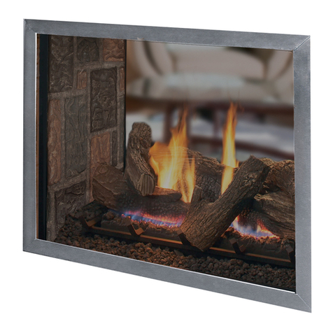
Step 7. Figure 4 shows the entire log set assembled. The volcanic stone
provided with the appliance (or sold separately) may be placed
one high in front of the front burner tube using care not to cover
all the burner ports. Any extra volcanic stone may be placed at
the ends of the front log, off the burner. Place small pinches of
glowing embers (rockwool) on top of the volcanic stone.
Figure 3
Pilot Viewing
Volcanic
Stone
Figure 4
Note the location of the hole for viewing the
pilot light. When the pilot is burning, a
blue flame can be seen through
this hole.
fire-parts.com
