Impulse TOTAL HIP IF8109 User manual

Table Of Contents
Read all precautions and instructions in this manual before using this
equipment.
! CAUTION
Important Safety Instructions-------------------------------------------------------------- 3
Instructions------------------------------------------------------------------------------------ 4
Parts List--------------------------------------------------------------------------------------- 5
Exploded View ------------------------------------------------------------------------------- 8
Measurement Guide------------------------------------------------------------------------ 9
Assembly Instructions--------------------------------------------------------------------- 10
Assembly------------------------------------------------------------------------------------- 11
Exercise Instructions----------------------------------------------------------------------19
Maintenance Schedule-------------------------------------------------------------------- 20
General Maintenance Information----------------------------------------------------- 21
Weight Training Tips--------------------------------------------------------------------- 22
Specifications------------------------------------------------------------------------------- 22

─ 3─
Important Safety Instructions
Before beginning any fitness program, you should obtain a complete physi-
cal examination from your physician. When using exercise equipment, basic
precautions should always be taken, including the following:
* Read all instructions before using the equipment. These instructions are
written to ensure your safety and to protect the unit.
* Do not allow children on or near the equipment.
* Use the equipment only for its intended purpose as described in this
guide. Do not use accessory attachments that are not recommended by
the manufacturer: such attachments might cause injuries.
* Wear proper exercise clothing and shoes for your workout----no loose
clothing.
* Be careful when getting on or off the equipment.
* Do not overexert yourself or work to exhaustion.
* If you feel any pain or abnormal symptoms, stop your workout immediately
and consult your physician.
* Never operate the unit when it has been dropped or damaged.
* Never drop or insert anything into any opening in the equipment.
* Always check the unit and its cables before each use. Make sure that all
fasteners and cables are secure and in good working condition.
* Frayed or worn cables can be dangerous and may cause injury.
Periodically check these cables for any indication of wear.
* Keep hands, limbs, loose clothing and long hair well out of the way of
moving parts.
* Do not attempt to lift more weight than you can control safely.
* Do not use the equipment outdoors.
Personal Safety During Assembly
* Read each step in the assembly instructions and follow the steps in
sequence. Do not skip ahead. If you skip ahead, you may learn later that
you have to disassemble components and that you may have damaged
the equipment.
* Assemble and operate the equipment on a solid, level surface. Locate the
unit a few feet from walls or furniture to provide easy access. The equip-
ment is designed for your enjoyment. By following these precautions and
using common sense, you will have many safe and pleasurable hours of
healthful exercise with the equipment.
Instructions
Before beginning assembly please take the time to read instructions
thoroughly. Please use the various lists in this manual to make sure that all
parts have been included in your shipment. When ordering, use part number
and description from the lists. Use only our replacement part when servicing.
Failure to do so will void your warranty and could result in personal injury.
The equipment is designed to provide the smoothest, most effective
exercise motion possible. After assembly, you should check all functions to
ensure correct operation. If you experience problems, first recheck the
assembly instructions to locate any possible errors made during assembly. If
you are unable to correct the problem, call your authorized dealer. Be sure to
have your serial number and this manual when calling. When all parts have
been accounted for, continue on.
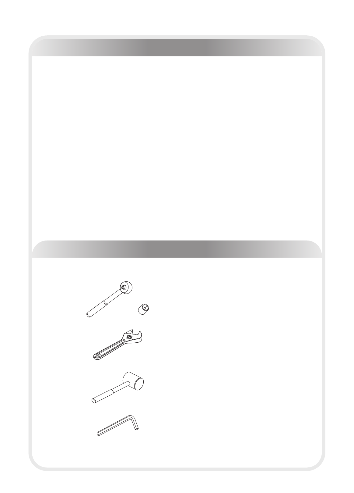
Tools Required
Ratchet Wrench and Socket
Adjustable Wrench
Rubber Mallet
Hex Key Wrench Set
─ 4─

─ 5─
Par ts List
NOTE: SOME OF THESE PARTS MAY COME PRE-INSTALLED
Item NO. Part NO. Description Qty
1 IF81090100 Weight Stack Frame 1
2 IF81090200 Bottom Cross Brace 1
3 IF81090300 Cross Brace 1
4 IF81090400 Cam 1
5 IF81090500 Sway Pulley Bracket 1
6 IF81090600 Left Armrest 1
7 IF81090700 Right Armrest 1
8 IF81090800 Swing Tube 1
9 IT90101000 Footstool Brace 1
10 SG-80096900 Pulley Forder 1
11 IF81091100 Cable 1
12 IF81211400 Spring Pin φ18.2*74 1
13 IF81091300 Scaleboard 1
14 IF81222700 Spring Pin φ18.3*122 1
15 IFPC2000 Grip φ36*φ28*535 2
16 IT80031200 Cap φ60*φ10.5*5 1
17 IN-S10111200 Spacer φ17*10.5 3
18 IF81051600 Cam Groove 5
19 IF81212400 Plastic Knob - Cap 2
20 IF81212300 Plastic Knob - Base 2
21 HF1652100 Plastic Washer φ60*φ25.7*3 2
22 IF81022000 End Capφ56*φ25.8*10.8 1
23 IF81092300 Roller 1
24 KF18606200 □50.8 Plug 2
25 IT90101800 Rubber Footplate Cover 1
26 SG500110400 4.5" Pulley 6
27 SPT-63200 Support 2
28 IF81162200 Top Shroud 1
29 IF81211600 Rear Shroud 1
30 IF81061500 Front Shroud 1
31 KFLPHS3000 □30*60 Plug 4
32 KFABM2100 □38 Plug 1
33 PL90165400 Top Plate 1
35 IF81162000 Foot Cover 4
36 IF81162100 Shroud Clip 4
37 PTSHILO12800 Weight Rubber Bumperφ76.2*φ26.9*38.1 2
38 IF81163500 Selector Pin W/Coil 1
39 IF81162700 Plastic Plate 2
40 IF81223900 Mount Sleeve φ40*25 2
41 IF81161400 Guide Rod φ25*2.5*1229 2
42 GB2766005-2Z Bearing 6005-2Z 4
43 HF1651600 Glide Sleeve 口50*口38 2
44 IF81212700 Nut 32*2.5*29 2
45 GB5780M10*110*30DS20NL Hex Head Bolts M10*110 1

─ 6─
Par ts List
NOTE: SOME OF THESE PARTS MAY COME PRE-INSTALLED
Item NO. Part NO. Description Qty
46 GB5780M10*105DS20 Hex Head Bolts M10*105 3
47 GB5780M10*75DS20 Hex Head Bolts M10*75 2
48 GB5780M10*80DS20 Hex Head Bolts M10*80 2
49 GB5780M10*135DS20 Hex Head Bolts M10*135 1
50 GB5780M10*50DS20 Hex Head Bolts M10*50 6
51 GB5780M10*45DS20 Hex Head Bolts M10*45 1
52 GB5781M10*25DS20NL Hex Head Bolts M10*25 1
53 PNLM10*25*25DS2NL Button Head Cap Screw M10*25 1
54 GB70M8*20DS2 Socket Head Cap Screw M8*20 3
55 PNLM8*25DS2 Button Head Cap Screw M8*25 10
56 PNLM6*15DS2 Button Head Cap Screw M6*15 2
57 GB77M8*8DS18 Socket Set Screw M8*8 4
58 GB819M5*15DS2 Flat Philips Screw M5*15 8
59 GB70M8*25*25DS2 Socket Head Cap Screw M8*25 1
60 GB41M10DS2 lock Nut M10 2
61 CNLM10*30*30DS2NL Flat Head Cap Screw M10*30 2
62 NM10DS2 Nylon lock Nut M10 15
63 NM8DS2 Nylon lock Nut M8 13
64 NM12DS2 Nylon lock Nut M12 4
65 DQ10DS2A Flat Washer φ11*φ23*2 31
66 DQ6DS2A Flat Washer φ6.6*φ15*2 2
67 GB958DS2 Flat Washer φ9*φ16*1.6 13
68 DQ12DS2A Flat Washer φ13*φ24*1.5 4
69 NBS4DHS Hex Key s=4 1
70 NBS5DHS Hex Key s=5 1
71 NBS6DHS Hex Key s=6 1
72 LW200BS Wrench 1
73 YHY Lube 1
74 H2-A070 Bushing φ10*φ14*20 1
76 SG8009C1000 Spacer φ31*φ25.4*6 1

─ 7─
Parts List-Weight Plates
!There are three configuration of weights: 170LBS/200LBS/ ,
please see following form for details.
250LBS
Item No. Part No. Description QTY
80 PLWS1000 Weight Plate 10LBS 16
Item No. Part No. Description QTY
80 PLWS1000 Weight Plate 10LBS 10
81 IF8WS1500 Weight Plate 15LBS 6
Item No. Part No. Description QTY
81 IF8WS1500 Weight Plate 15LBS 16
Weight Plate 170LBS
Weight Plate 200LBS
Weight Plate 250LBS

─ 8 ─
Exploded View

─ 9 ─
SHCS = Socket Head Cap Screw
FHCS = Flat Head Cap Screw
HHB = Hex Head Bolt
BHCS = Button Head Cap Screw
Measurement Guide

Assembly of the takes professional installers about 2 hours. If this is
the first time you have assembled this type of equipment, plan to spend more
time. It is strongly recommended to assemble the equipment by professional in-
stallers. You may find it quicker, safer, easier to assemble this equipment with
the help of a friend, as some of components may be large, heavy or awkward to
handle alone. It is important that you assemble your product in a clean, clear,
uncluttered area. This will enable you to move around the product while you are
fitting components and reduce the possibility of injury during assembly.
As with any assembled part, proper alignment and adjustment is critical. While
tightening the fasteners, be sure to leave room for adjustments. Do not fully
tighten the fasteners until instructed to do so. Be careful to assemble the com-
ponents in the sequence presented in this guide.
equipment
Assembly Instructions
─ 10 ─

─ 11 ─
Assembly
Step 1
1. Attach the Bottom Cross Brace (#2) to the Weight Stack Frame (#1) , using:
one M10*105 HHB (#46) one M10*110 HHB (#45)
three Φ11*Φ23*2 Flat Washers (#65) one M10 Nylon lock Nut (#62)
2. Attach the Cross Brace (#3) to the Weight Stack Frame (#1) and the Bottom
Cross Brace (#2),using:
two M10*105 HHB (#46) two M10*75 HHB (#47)
eight Φ11*Φ23*2 Flat Washers (#65) four M10 Nylon lock Nut (#62)
3. Attach the Footstool Brace (#9) to the Bottom Cross Brace (#2),using:
four Φ13*Φ24*1.5 Flat Washers(#68) four M12 Nylon lock Nut (#64)
4. Attach four Shroud Clip (#36)to the Weight Stack Frame (#1),using:
eight M5*15 Flat Philips Screw(#58)
Note:Hand tighten bolts and Nylon Lock nuts until machine is fully assembled.
─ 12 ─
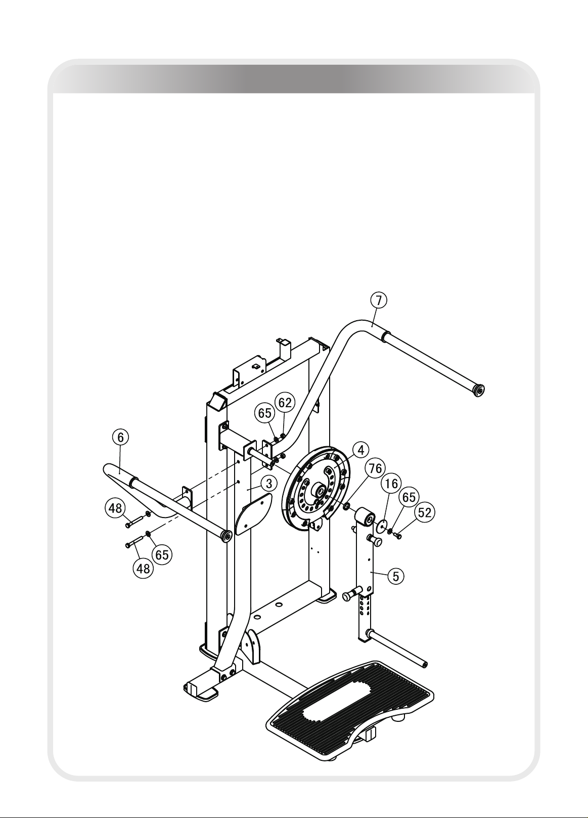
Assembly
Step 2
1.Attach the Left Armrest (#6) and the Right Armrest (#7) to the Cross Brace (#3),
using:
two M10*80 HHB (#48) four Φ11*Φ23*2 Flat Washers (#65)
two M10 Nylon lock Nuts (#62)
2.Attach the Cam (#4) and the Sway Pulley Bracket (#5) to the Cross Brace (#3),
using:
one Φ31*Φ25.4*6 Spacer (#76) one Φ60*Φ10.5*5 Cap (#16)
one Φ11*Φ23*2Flat Washer (#65) one M10*25 HHB (#52)
Note:Hand tighten bolts and Nylon Lock nuts until machine is fully assembled.

─ 13 ─
Assembly
Step 3
1.Attach six 4.5" Pulley (#26) to the Weight Stack Frame (#1) and the Bottom
Cross Brace (#2) and the Cross Brace (#3) , using:
six M10*50 HHB (#50) twelve Φ11*Φ23*2 Flat Washers (#65)
six M10 Nylon lock Nuts (#62) one Pulley Forder (#10)
2. Attach the Cable (#11) to the Cam (#4),using:
one M10*45 HHB (#51) two Φ11*Φ23*2 Flat Washers (#65)
one M10 Nylon lock Nut (#62) one Φ10*Φ14*20 Bushing (#74)
Note: Hand tighten bolts and Nylon Lock nuts until machine is fully assembled.

─ 14 ─
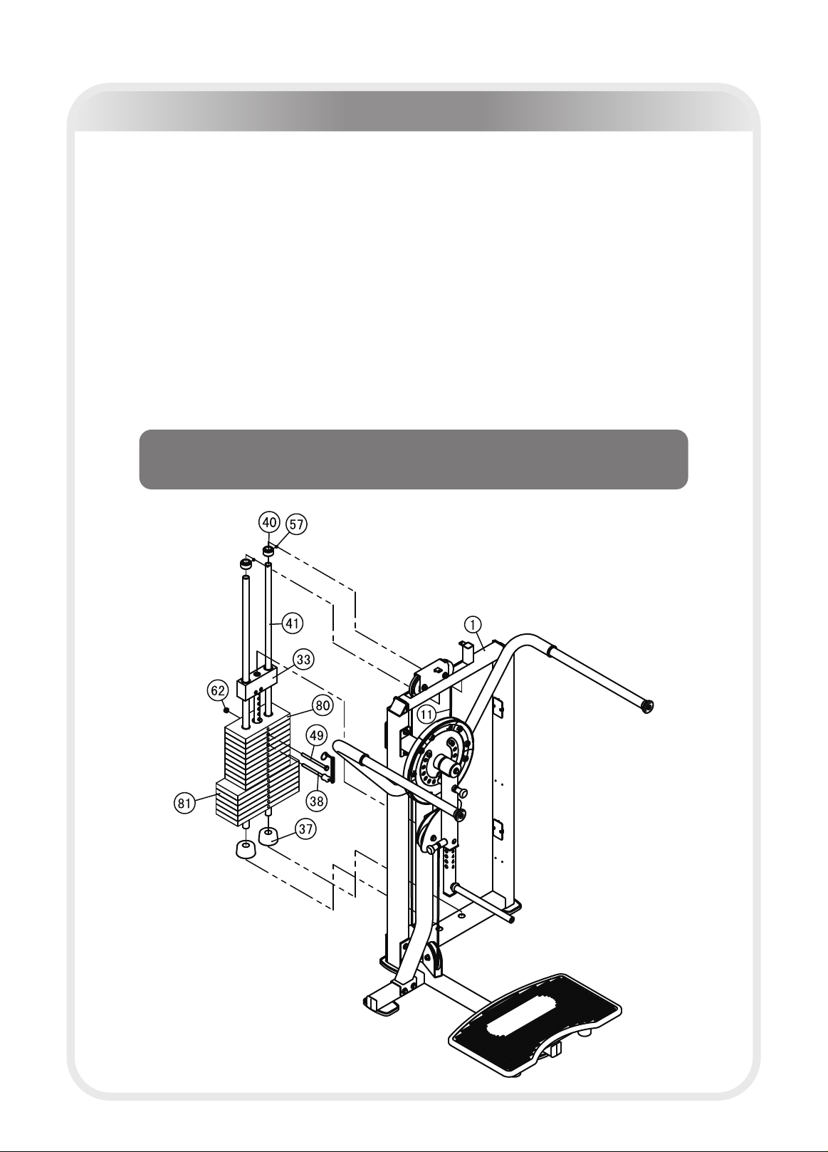
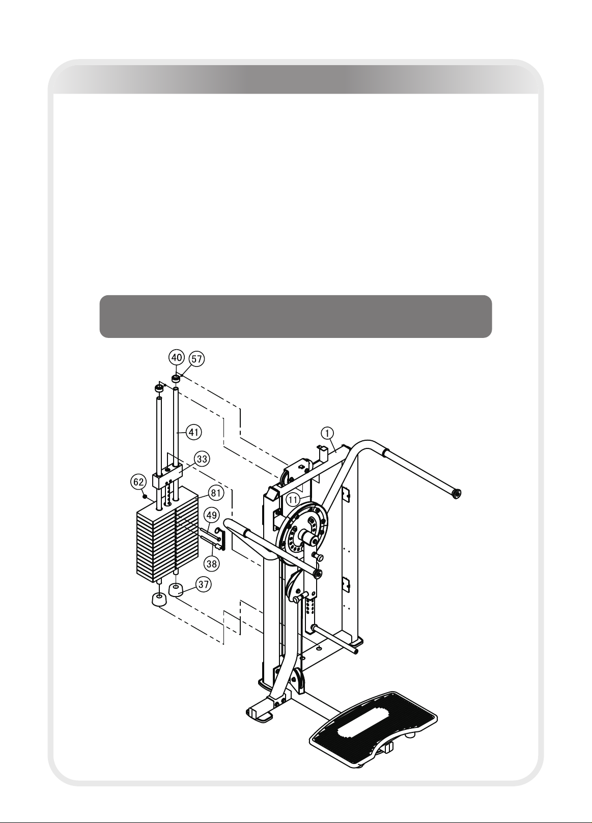
Step 4
1.Attach:
two Φ25*2.5*1229 Guide Rod (#41) two Φ76.2*Φ26.9*38.1 Weight Rubber Bumper (#37)
sixteen 10LBS Weight Plates (#80) one Top Plate(#33)
to the Weight Stack Frame (#1),using:
two Φ40*25 Mount Sleeves (#40) four M8*8 Socket Set Screws (#57)
2.Attach the Selector Pin W/Coil (#38) to the Top Plate (#33);
3.Attach the second 10LBS Weight Plate (#80) to the Top Plate (#33),using:
one M10*135 HHB (#49) one M10 Nylon lock Nut (#62)
.
Note: Hand tighten bolts and nylon lock nuts until machine is fully assembled.
4 Attach the Cable (#11) to the Top Plate (#33).
Assembly-170LBS
Here is the assembly instruction for 170LBS weights.
Please assemble according to the actual weights you buy.
─ 15 ─
Assembly-200LBS
Here is the assembly instruction for 200LBS weights.
Please assemble according to the actual weights you buy.
Step 4
1.Attach:
two Φ25*2.5*1229 Guide Rod (#41) two Φ76.2*Φ26.9*38.1 Weight Rubber Bumper(#37)
ten 10LBS Weight Plates (#80) six 15LBS Weight Plates (#81)
one Top Plate(#33)
to the Weight Stack Frame (#1),using:
two φ40*25 Mount Sleeves (#40) four M8*8 Socket Set Screws (#57)
2. Attach the Selector Pin W/Coil (#38) to the Top Plate (#33);
3. Attach the second 10LBS Weight Plate (#80) to the Top Plate (#33),using:
one M10*135 HHB(#49) one M10 Nylon lock Nut (#62)
Note:Hand tighten bolts and Nylon Lock nuts until machine is fully assembled.
4.Attach the Cable (#11) to the Top Plate (#33).
─ 16 ─
Assembly-250LBS
Here is the assembly instruction for 250LBS weights.
Please assemble according to the actual weights you buy.
Step 4
1.Attach:
two Φ25*2.5*1229 Guide Rod (#41) two Φ76.2*Φ26.9*38.1 Weight Rubber Bumper (#37)
sixteen 15LBS Weight Plates (#81) one Top Plate(#33)
to the Weight Stack Frame (#1),using:
two Φ40*25 Mount Sleeves (#40) four M8*8 Socket Set Screws (#57)
2.Attach the Selector Pin W/Coil (#38) to the Top Plate (#33);
3.Attach the second 15LBS Weight Plate (#81) to the Top Plate (#33),using:
one M10*135 HHB (#49) one M10 Nylon lock Nut (#62)
Note: Hand tighten bolts and nylon lock nuts until machine is fully assembled.
4.Attach the Cable (#11) to the Top Plate (#33).

─ 17 ─
Assembly
Step 5
Attach one Roller (#23) to the Swing Tube (#8),using:
one Φ11*Φ23*2 Flat Washer (#65) one Φ56*Φ25.8*10.8 End Cap (#22)
two Φ60*Φ25.7*3 Plastic Washer (#21)
Note:Wrench Tighten bolts and Nylon Lock nuts.
one M10*25 BHCS (#53)
─ 18 ─
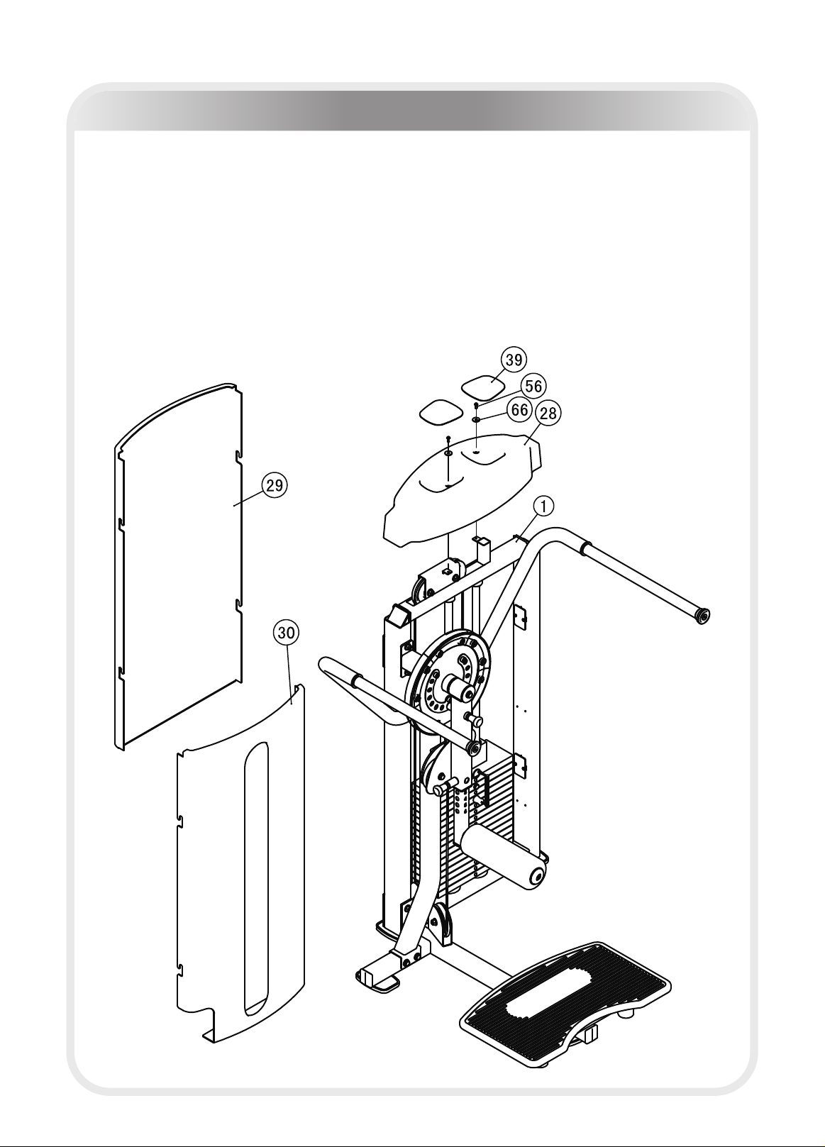
Assembly
Step 6
1.Attach the Front Shroud (#30) and the Rear Shroud (#29) to the Weight Stack
Frame (#1);
2.Attach the Top Shroud (#28) to the Weight Stack Frame (#1),using:
two M6*15 BHCS(#56) two Φ6.6*Φ15*2 Flat Washers (#66)
Note: Wrench Tighten bolts and Nylon Lock nuts.
1 Select an appropriate weight.
2 Adjust foam roller for desired position.
3 Leg press foam roller to do actions.
4 Slowly return to the starting position.
8109
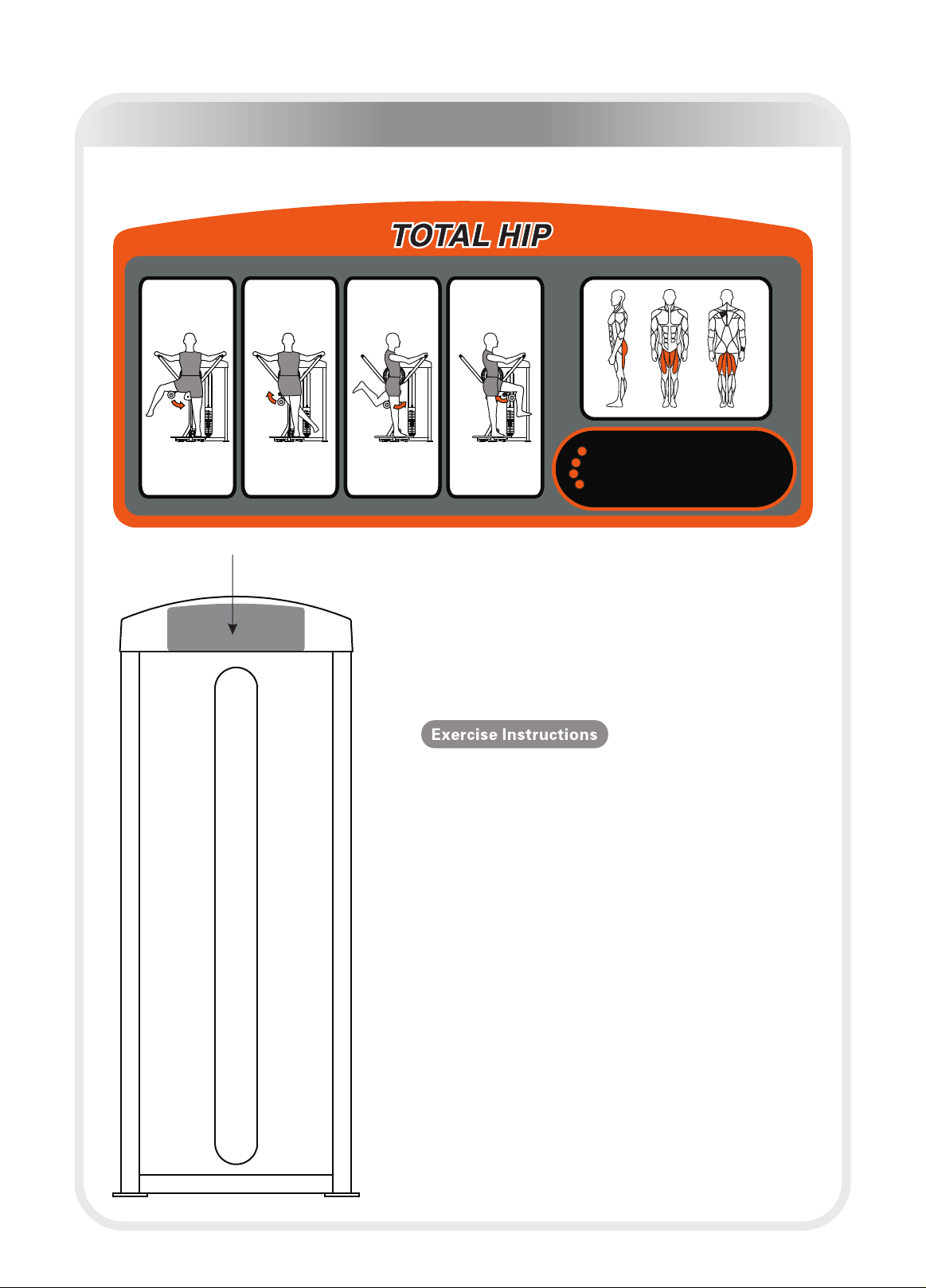
Exercise Instructions
(Adjust weight according to the select pin)
─ 19 ─
1.Select an appropriate weight.
2.Adjust foam roller for desired position.
3.Leg press foam roller to do actions.
4.Slowly return to the starting position.

Maintenance Schedule
Your equipment comes with a commercial maintenance decal. For personal,
in home use, please follow the home maintenance schedule listed above.
ROUTINE COMMERCIAL
MAINTENANCE
HOME
MAINTENANCE
Inspect;
Links, Pull Pins, Snap Locks,
Swivels, Weight Stack Pins
DAILY WEEKLY
Clean;
Upholstery DAILY WEEKLY
Inspect;
Cables or Belts and their tension DAILY WEEKLY
Inspect;
Accessory Bars, and Handles WEEKLY 3 MONTHS
Inspect;
All Decals WEEKLY 3 MONTHS
Inspect;
All Nuts and Bolts, Tighten if
needed
WEEKLY 3 MONTHS
Inspect;
Anti-Skid Surface WEEKLY 3 MONTHS
Clean & Lubricate;
Guide Rods with a Teflon (PTFE)
based lubricant (Superlube)
MONTHLY 3 MONTHS
Lubricate;
Seat Sleeves, Turcite Bushings,
Linear Bearing
MONTHLY 3 MONTHS
Clean and Wax;
All Glossy Finishes 6 MONTHS YEARLY
Repack with Grease;
Linear Bearings 6 MONTHS YEARLY
Replace;
Cables, Belts and Connecting
Parts
YEARLY 3 YEARS
LATEST DATE ENTRY
─ 20 ─
Table of contents
Other Impulse Fitness Equipment manuals

Impulse
Impulse IT8018 User manual

Impulse
Impulse IT8016 User manual

Impulse
Impulse IT6015B User manual

Impulse
Impulse IT8005 User manual

Impulse
Impulse HSP-PRO002 User manual

Impulse
Impulse SL7043 User manual

Impulse
Impulse SL7046 User manual

Impulse
Impulse IT8010 User manual

Impulse
Impulse IT8023 User manual

Impulse
Impulse IF8 121 User manual

Impulse
Impulse SL7041 User manual

Impulse
Impulse IFP1302 User manual

Impulse
Impulse SL7038 User manual

Impulse
Impulse IT8009 Total Hip User manual

Impulse
Impulse SL7035 User manual

Impulse
Impulse IF9325 User manual

Impulse
Impulse SL7040 User manual

Impulse
Impulse SL7039 User manual

Impulse
Impulse SL7045OPT User manual

Impulse
Impulse HSR007 User manual


