Impulse SL7038 User manual
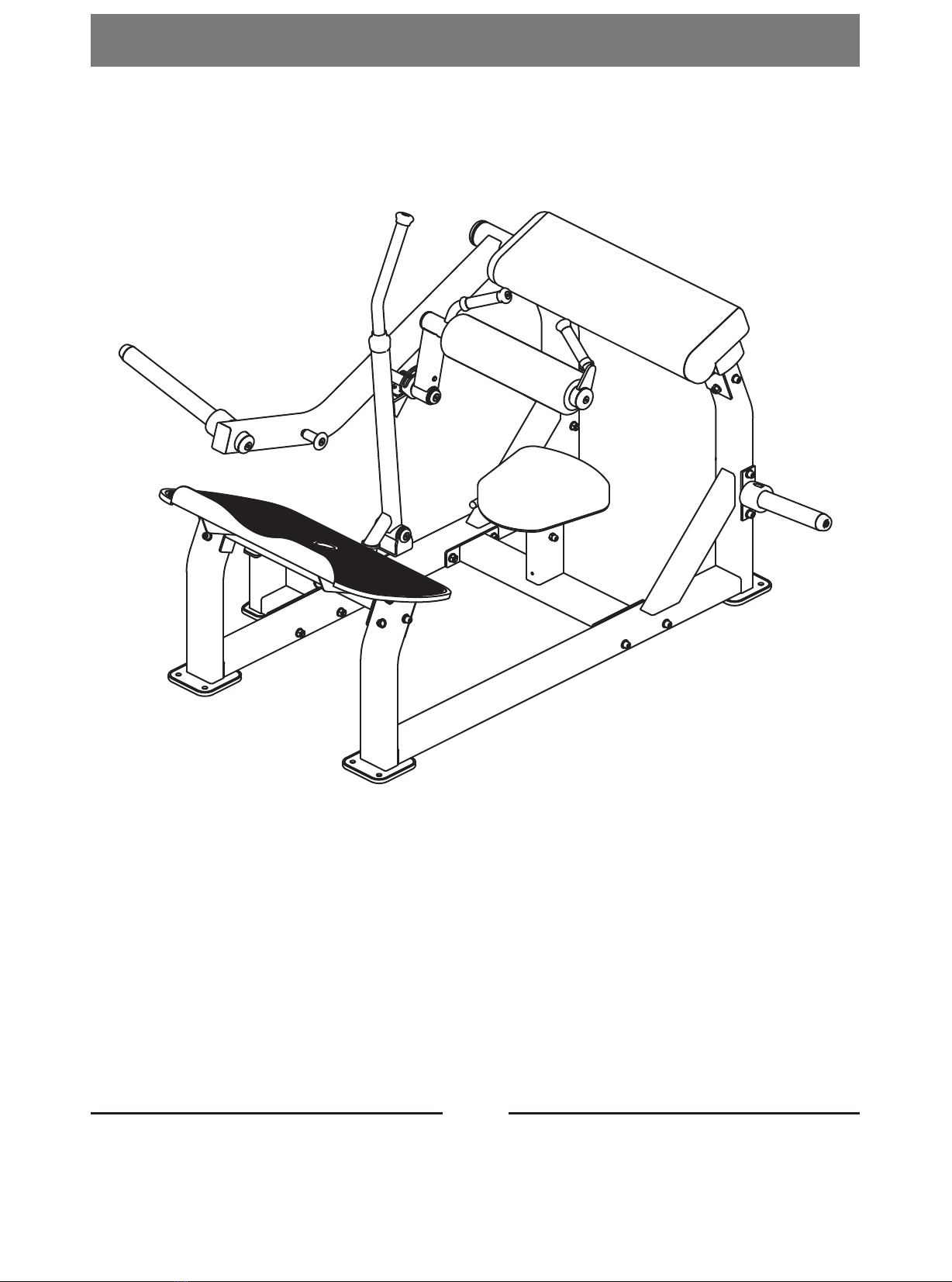
CAUTION! Read all precautions and instructions in this manual
before using this equipment.
21P
SL7038
Glute Trainer
Owner's Manual

Table Of Contents
CAUTION!
Read all precautions and instructions in this manual before using this equipment.
Important Safety Instructions----------------------------------------------------------- 3
Instructions-------------------------------------------------------------------------------- 5
Exploded View and Parts List------------------------------------------------------------ 6
Measurement Guide--------------------------------------------------------------------- 15
Assembly Instructions------------------------------------------------------------------ 16
Assembly--------------------------------------------------------------------------------- 17
Adjust Instructions---------------------------------------------------------------------- 21
Exercise Instructions-------------------------------------------------------------------- 22
Maintenance Schedule------------------------------------------------------------------ 23
General Maintenance Information----------------------------------------------------- 24
Weight Training Tips-------------------------------------------------------------------- 25

3
Important Safety Instructions
Before beginning any fitness program, you should obtain a complete physical
examination from your physician. When using exercise equipment, basic
precautions should always be taken, including the following:
1. Read all instructions before using the equipment.
These instructions are written to ensure your safety and to protect the unit.
2. Use the equipment only for its intended purpose as described in this guide.
Do not use accessory attachments that are not recommended by the
manufacturer: such attachments might cause injuries.
3. The product should only be used on a level surface and is with 0.5 meters
space around the product.
Do not use the equipment outdoors.
4. Do not allow children on or near the equipment. And children are not allowed
to use this equipment.
Teenagers should use this equipment with adult supervision.
5. Do not overexert yourself or work to exhaustion.
Do not attempt to lift more weight than you can control safely.
If you feel any pain or abnormal symptoms, stop your workout immediately
and consult your physician.
6. This equipment is not used as medical apparatus and instruments.
7. Never operate the unit when it has been dropped or damaged.
Never drop or insert anything into any opening in the equipment.
Always check the unit and its cables before each use. Make sure that all
fasteners and cables are secure and in good working condition.
Frayed or worn cables can be dangerous and may cause injury. Periodically
check these cables for any indication of wear.
Keep hands, limbs, loose clothing and long hair well out of the way of moving
parts.
8. Be careful when getting on or off the equipment.
9. Wear proper exercise clothing and shoes for your workout, no loose clothing.

Specifications
Class: S
Maximum Wt. Capacity: 150kg/ 330lbs
Maximum User Weight: 150kg/ 330lbs
Product Dimension: 1650*1618*1106mm
Product Total Surface: 1650*1618mm
Product Total Mass: 114.7kg/ 253lbs
Training Area and Free Area
4
Important Safety Instructions
Personal Safety During Assembly
Read each step in the assembly instructions and follow the steps in sequence.
Do not skip ahead. If you skip ahead, you may learn later that you have to
disassemble components and that you may have damaged the equipment.
Assemble and operate the equipment on a solid, level surface. Locate the unit
a few feet from walls or furniture to provide easy access. The equipment is
designed for your enjoyment. By following these precautions and using
common sense, you will have many safe and pleasurable hours of healthful
exercise with the equipment.

5
Instructions
Tools Required
The equipment is designed to provide the smoothest, most effective exercise
motion possible. After assembly, you should check all functions to ensure correct
operation. If you experience problems, first recheck the assembly instructions to
locate any possible errors made during assembly. If you are unable to correct the
problem, call your authorized dealer. Be sure to have your serial number and this
manual when calling. When all parts have been accounted for, continue on.
Ratchet Wrench and Socket
Adjustable Wrench
Rubber Mallet
Hex Key Wrench Set
Phillips Screwdriver
Before beginning assembly please take the time to read instructions thoroughly.
Please use the various lists in this manual to make sure that all parts have been
included in your shipment. When ordering, use part number and description from
the lists. Use only our replacement part when servicing. Failure to do so will void
your warranty and could result in personal injury.

6
Exploded View and Parts List
Overall
ItemNo. Grade No. Part No. Description QTY
1 1 SL703801ASSY Floor Stand Frame 1 ASSY 1
2 2 SL703802ASSY Floor Stand Frame 2 ASSY 1
3 3 SL703804ASSY Back Pad Frame ASSY 1
4 4 SL703807ASSY Seat Pad Frame ASSY 1
5 5 SL703808ASSY Pedal Plate Frame ASSY 1
6 6 SL703809ASSY Bottom Support Frame ASSY 1
7 7 SL70381000 Adjustable Seat Pad Frame 1
8 8 SL704008ASSY Long Weitht Horn Frame ASSY 1
9 9 SL703911ASSY Short Weitht Horn Frame ASSY 2
10 10 PL0702900 Rubber Bumper Φ76*64.6 1
11 11 IT80053700 Plastic Ring Φ90*Φ51.5*6 2
12 12 SL703803ASSY Swing Frame ASSY 1
13 13 SL703805ASSY Foam Frame ASSY 1
14 14 SL703806ASSY Safety Frame ASSY 1
15 15 SL703811ASSY Outside Handle Frame ASSY 1
16 16 SL703812ASSY Adjustable Handle Frame ASSY 1
17 17 SL70385100 Back Pad 1
18 18 SL70062600V1 Seat Pad 1
19 19 IF81241100V2 FOAM ASSY 1
20 20 IE950716500 Aluminum Cap Φ60*11.6 1
21 21 RL81052200 Aluminum Cap Φ72*14.4 1
22 22 SL70011700 Aluminum Cap Φ54*Φ12.5*10.6 1
23 23 SL70022500 RingΦ46*Φ30.5*3 1
24 24 ST70131800 Axis Φ25.4*76 1
25 25 IN-D21202000 Aluminum Cap Φ38*Φ10.5*8 3
26 26 GB70M12*125DHS20 Socket Head Cap Screw M12*125 10
27 27 GB70M12*75DHS20 Socket Head Cap Screw M12*75 9
28 28 GB77M8*6DS18NL Hexagon Socket Set Screws M8*6 2
29 29 CNLM12*50*50DS20NL Flat Head Cap Screw M12*50 1
30 30 GB70M10*80DHS20 Socket Head Cap Screw M10*80 2
31 31 GB70M10*30DHS20 Socket Head Cap Screw M10*30 2
32 32 CNLM10*50DS20 Flat Head Cap Screw M10*50 1
33 33 CNLM10*25DS20 Flat Head Cap Screw M10*25 4
34 34 GB70M8*30DHS20 Sock et Head Cap Screw M8*30 2
35 35 GB9312DHS12 Spring Washer Φ12 2
36 36 GB938DHS12 Spring Washer Φ8 2
37 37 GB9512DHS2 Flat Washer Φ13*Φ24*2.5 44
38 38 GB9510DHS2 Flat Washer Φ11*Φ20*2 4
39 39 NM12DHS2 Nylon Lock Nut M12 21
40 40 NBS4DHS Hex Key S=4 1
41 41 NBS10DHS Hex Key S=10 1
42 42 NBS8DHS Hex Key S=8 1
43 43 NBS6DHS Hex Key S=6 1
44 44 LW200BS Wrench Φ6*117 1

7
Exploded View and Parts List
Overall

8
Exploded View and Parts List
Floor Stand Frame 1 ASSY Floor Stand Frame 2 ASSY
ItemNo. Grade No. Part No. Description QTY
1 1.1 SL70380100 Floor Stand Frame 1 1
2 1.2 CWRVL0051200 Rubber Foot 2
ItemNo. Grade No. Part No. Description QTY
1 2.1 SL70380200 Floor Stand Frame 2 1
2 2.2 SL70383100 Rotating Sleeve Φ26*3*55 1
3 2.3 IN-S51102100 Aluminum Cap Φ50*Φ10.5*8 1
4 2.4 CWRVL0051200 Rubber Foot 2
5 2.5 CNLM10*25DS20 Flat Head Cap Screw M10*25 1

9
Exploded View and Parts List
Back Pad Frame ASSY Seat Pad Frame ASSY
ItemNo. Grade No. Part No. Description QTY
1 3.1 SL70380400 Back Pad Frame 1
2 3.2 VLP8000 Pulg □50*100 1
ItemNo. Grade No. Part No. Description QTY
1 4.1 SL70380700 Seat Pad Frame 1
2 4.2 IF93035000 Inner Wear Sleeve 2
3 4.3 GB70M10*30DHS20 Socket Head Cap Screw M10*30 1

10
Exploded View and Parts List
Pedal Plate Frame ASSY Bottom Support
Frame ASSY
ItemNo. Grade No. Part No. Description QTY
1 5.1 SL70380800 Pedal Plate Frame 1
2 5.2 SL70064000 Rubber Foot Plate Cover 1
3 5.3 SL70064100 Plastic Pin 6
4 5.4 SL70064200 Plastic Cover 6
ItemNo. Grade No. Part No. Description QTY
1 6.1 SL70380900 Bottom Support Frame 1
2 6.2 IF81162000 Rubber Foot 1
3 6.3 PL380800 Urethane Bumper 1
4 6.4 GB9512DHS2 Flat Washer Φ13*Φ24*2.5 2
5 6.5 GB70M12*35DHS20 Socket Head Cap Screw M12*35 2

11
Exploded View and Parts List
Long Weight Horn
Frame ASSY
Short Weight Horn
Frame ASSY
ItemNo. Grade No. Part No. Description QTY
1 9.1 SL70391100 Short Plate Support Frame 1
2 9.2 PL0702800 Short Weight Horn Sleeve 1
3 9.3 PL0702300 Plastic Cap Φ49*Φ12.5*25 1
4 9.4 PL4003200 Rubber Bumper Φ76.2*62.2 1
5 9.5 GB70M12*35N19 Socket Head Cap Screw M12*35 1
ItemNo. Grade No. Part No. Description QTY
1 8.1 SL70400800 Long Plate Support Frame 1
2 8.2 HSP70522000 Long Weight Horn Sleeve 1
3 8.3 SL70012000 Plastic Cap 1
4 8.4 GB70M12*30DS20NL Socket Head Cap Screw M12*30 1

12
Exploded View and Parts List
Swing Frame ASSY FOAM Frame ASSY
ItemNo. Grade No. Part No. Description QTY
1 13.1 SL70380500 FOAM Frame 1
2 13.2 FS573600 Bush Φ44*Φ36*Φ30*19.5 2
3 13.3 B10009900 PulgΦ50.8 1
4 13.4 026-01PL0206-5 Grip STΦ31*Φ24*111 1
5 13.5 IT90102100 Aluminum Grip Cap Φ25 1
6 13.6 IT90102200 Aluminum Grip Ring Φ25 1
7 13.7 IF81165000 Nut M10 1
8 13.8 CNLM10*35DS20 Flat Head Cap Screw M10*35 1
9 13.9 YZGB7710-32*3.2N19 Socket Set Screw 10-32UNF*3.2 2
ItemNo. Grade No. Part No. Description QTY
1 12.1 SL70380300 Swing Frame 1
2 12.2 SL70383100 Plastic Sleeve Φ26*3*55 1
3 12.3 IN-S51102100 Aluminum Cap Φ50*Φ10.5*8 1
4 12.4 KPSFID2800 Pulg □50.8*76.2 1
5 12.5 CNLM10*25DS20 Flat Head Cap Screw M10*25 1
6 12.6 GB2766206-2ZC3 Bearing 6206-2ZC3 2

13
Exploded View and Parts List
Safety Frame ASSY
ItemNo. Grade No. Part No. Description QTY
1 14.1 SL70380600 Safety Frame 1
2 14.2 SL70383200 Plastic Board 1 1
3 14.3 SL70383300 Plastic Board 2 1
4 14.4 RL81013400 Connective Sleeve 1
5 14.5 026-01PL0235-11 Grip Φ36*Φ29*338 1
6 14.6 CGH4501300 Plastic Sleeve 1
7 14.7 PBG10002 Rubber Bumper 1
8 14.8 M02502000 Bush Φ38*Φ32*Φ25.4*18 2
9 14.9 IT90122000 Aluminum Grip Cap Φ32 1
10 14.10 IF81212700 Nut M10 1
11 14.11 GB70M10*30DHS20 Socket Head Cap Screw M10*30 1
12 14.12 GB819M6*12DHS2 Cross Recessed Countersunk Head Screw M6*12 4
13 14.13 CNLM10*35*35DS20 Flat Head Cap Screw M10*35 1

14
Exploded View and Parts List
Outside Handle Frame ASSY Adjustable Handle
Frame ASSY
ItemNo. Grade No. Part No. Description QTY
1 15.1 SL70380600 Outside Handle Frame 1
2 15.2 IT90102100 Aluminum Grip Cap Φ25 1
3 15.3 IT90102200 Aluminum Grip Ring Φ25 1
4 15.4 026-01PL0206-5 Grip STΦ31*Φ24*111 1
5 15.5 IF81165000 Nut M10 1
6 15.6 CNLM10*35*35DS20 Flat Head Cap Screw M10*35 1
7 15.7 YZGB7710-32*3.2N19 Socket Set Screw 10-32UNF*3.2 2
ItemNo. Grade No. Part No. Description QTY
1 16.1 SL70381200 Adjustable Handle Frame 1
2 16.2 M01402000 Bush Φ25*Φ18*Φ12.2*13 2
3 16.3 CG50001700 Grip DTΦ19*Φ14*70 1
4 16.4 KPS18002701V1 Lock Nut 1
5 16.5 FE97161700 Roll Pin Φ18.2*71 1
6 16.6 CF217903100 Spring Φ13*Φ1.4*38.6 1
7 16.7 GB/T1243-199708BN19 Connecting Shackle P=12.7 1

Inches
Millimeters
BHCS = Button Head Cap Screw
SHCS = Socket Head Cap Screw
FHCS = Flat Head Cap Screw
HHB = Hex Head Bolt
Measurement Guide
Diameter of bolt
(mm/inch) M6(1/4") M8(5/16") M10(3/8") M12(1/2") M16(5/8")
Tightening
torque (N.m) 9~12 22~30 45~59 78~104 193~257
Operational
methods for
adult men
The strength of
the wrist
The strength of
the wrist and
forearm
The strength of
the entire arm
The strength of
the arm and
upper body
with all strength
15

16
Assembly Instructions
Assembly of the equipment takes professional installers about 2 hours. If this
is the first time you have assembled this type of equipment, plan to spend
more time. It is strongly recommended to assemble the equipment by
professional installers. You may find it quicker, safer, easier to assemble this
equipment with the help of a friend, as some of components may be large,
heavy or awkward to handle alone. It is important that you assemble your
product in a clean, clear, uncluttered area. This will enable you to move around
the product while you are fitting components and reduce the possibility of
injury during assembly.
As with any assembled part, proper alignment and adjustment is critical. While
tightening the fasteners, be sure to leave room for adjustments. Do not fully
tighten the fasteners until instructed to do so. Be careful to assemble the
components in the sequence presented in this guide.
NOTE

STEP 1
1. Attach the Seat Pad Frame ASSY (#4) to the Floor Stand Frame 1 ASSY (#1) and the
Floor Stand Frame 2 ASSY (#2) using:
four M12*125 SHCS (#26) eight Φ13*Φ24*2.5 Flat Washer (#37)
four M12 Nylon Lock Nut (#39)
2. Attach the Back Pad Frame ASSY (#3) to the Floor Stand Frame 1 ASSY (#1) and the
Floor Stand Frame 2 ASSY (#2) using:
two M12*125 SHCS (#26) four M12*75 SHCS (#27)
twelve Φ13*Φ24*2.5 Flat Washer (#37) six M12 Nylon Lock Nut (#39)
3. Attach the Pedal Plate Frame ASSY (#5) to the Floor Stand Frame 1 ASSY (#1) and the
Floor Stand Frame 2 ASSY (#2) using:
two M12*125 SHCS (#26) four M12*75 SHCS (#27)
ten Φ13*Φ24*2.5 Flat Washer (#37) two Φ12 Spring Washer (#35)
four M12 Nylon Lock Nut (#39)
Note: Wrench Tighten Bolts and Nylon Lock Nuts.
Assembly
17

Assembly
18
STEP 2
1. Attach the Safety Frame ASSY (#14) to the Floor Stand Frame 2 ASSY (#2) using:
one Φ25.4*76 Axis (#24) two Φ38*Φ10.5*8 Aluminum Cap (#25)
two M10*25 FHCS (#33)
2. Attach the Bottom Support Frame ASSY (#6) to the Floor Stand Frame 2 ASSY (#2)
using:
two M12*125 SHCS (#26) four Φ13*Φ24*2.5 Flat Washer (#37)
two M12 Nylon Lock Nut (#39)
3. Attach the Swing Frame ASSY (#12) to the Back Pad Frame ASSY (#3) using:
one Φ46*Φ30.5*3 Ring (#23) one Φ72*14.4 Aluminum Cap (#21)
one M10*25 FHCS (#33)
Note: 1. The Swing Frame ASSY (#12) above the Safety Frame ASSY (#14).
2. Wrench Tighten Bolts and Nylon Lock Nuts.

Assembly
19
STEP 3
1. Attach the Adjustable Handle Frame ASSY (#16) to the Seat Pad Frame ASSY (#4) using:
one M12*75 SHCS (#27) two Φ13*Φ24*2.5 Flat Washer (#37)
one M12 Nylon Lock Nut (#39)
2. Attach the Adjustable Seat Pad Frame (#7) to the Seat Pad Frame ASSY (#4).
3. Attach the Foam Frame ASSY (#13) to the Swing Frame ASSY (#12) using:
one Φ38*Φ10.5*8 Aluminum Cap (#25) one M10*25 FHCS (#33)
4. Attach the Long Weitht Horn Frame ASSY (#8) to the Swing Frame ASSY (#12) using:
one Φ54*Φ12.5*10.6 Aluminum Cap (#22) one M12*50 FHCS (#29)
two M8*6 Hexagon socket set screws (#28) one bumper (#10)
5. Attach two Short Weitht Horn Frame ASSY (#9) to the Floor Stand Frame 1 ASSY (#1)
and the Floor Stand Frame 2 ASSY(#2) using:
four M12*125 SHCS (#26) eight Φ13*Φ24*2.5 Flat Washer (#37)
four M12 Nylon Lock Nut (#39)
Note: Wrench Tighten Bolts and Nylon Lock Nuts.

Assembly
20
STEP 4
1. Attach the FOAM ASSY (#19) and the Outside Handle Frame ASSY (#15) to the Foam
Frame ASSY (#13) using:
two Φ90*Φ51.5*6 Plastic Ring (#11)
two Φ8 Spring Washer (#36)
two M8*30 SHCS (#34)
one Φ60*11.6Aluminum Cap (#20)
one M10*50 FHCS (#32)
2. Attach the Seat Pad (#18) to the Adjustable Seat Pad Frame (#7) using:
two M10*30 SHCS (#31)
two Φ11*Φ20*2Flat Washer (#38)
3. Attach the Back Pad (#17) to the Back Pad Frame ASSY (#3) using:
two M10*80 SHCS (#30)
two Φ11*Φ20*2Flat Washer (#38)
Note: Wrench Tighten Bolts and Nylon Lock Nuts.
Table of contents
Other Impulse Fitness Equipment manuals

Impulse
Impulse IT8001 User manual

Impulse
Impulse IT8005 User manual

Impulse
Impulse SL7045OPT User manual

Impulse
Impulse SL7041 User manual

Impulse
Impulse SL7039 User manual

Impulse
Impulse HSR007 User manual

Impulse
Impulse IF8 121 User manual

Impulse
Impulse IT8018 User manual

Impulse
Impulse IT8010 User manual

Impulse
Impulse IT7006 User manual

Impulse
Impulse IT8016 User manual

Impulse
Impulse IT8022 User manual

Impulse
Impulse IF9303 User manual

Impulse
Impulse SL7035 User manual

Impulse
Impulse TOTAL HIP IF8109 User manual

Impulse
Impulse IT8012 User manual

Impulse
Impulse IT9022 User manual

Impulse
Impulse SL7046 User manual

Impulse
Impulse SL7043 User manual

Impulse
Impulse IT8002 User manual