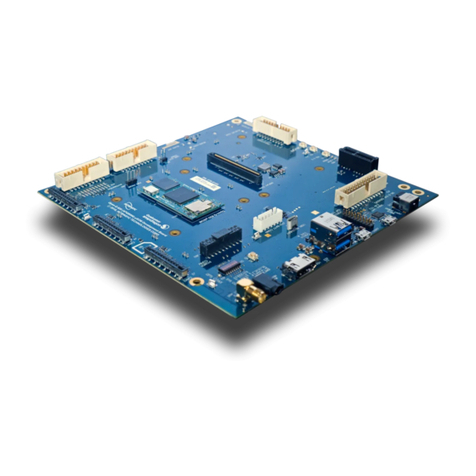
Open-Q™ 670 HDK Hardware Development Kit User Guide Version 1.0
3
Copyright Intrinsyc Technologies Corporation
Table of Contents
1. INTRODUCTION...................................................................................4
1.1 Purpose ..................................................................................................... 4
1.2 Scope......................................................................................................... 4
1.3 Intended Audience................................................................................... 4
2. DOCUMENTS.......................................................................................5
2.1 Applicable Documents............................................................................. 5
2.2 Reference Documents............................................................................. 5
2.3 Terms and Acronyms .............................................................................. 5
2.4 List of Figures........................................................................................... 6
2.5 List of Tables............................................................................................. 6
3. OPEN-Q 670 HARDWARE DEVELOPMENT KIT................................7
3.1 Introduction ............................................................................................... 7
3.2 Development Platform Notice................................................................ 7
3.3 Anti-Static Handling Procedures............................................................ 7
3.4 Kit Contents............................................................................................... 8
3.5 Hardware Identification Label................................................................. 9
3.6 System Block Diagram.......................................................................... 10
3.7 Open-Q 670 HDK Processor Board.................................................... 11
3.7.1 Processor Board Mechanical Properties........................................................... 12
3.7.2 Processor Board Block Diagram........................................................................ 12
3.7.3 Hardware Specification........................................................................................... 14
3.8 Open-Q 670 HDK Carrier Board.......................................................... 16
3.8.1 Dip switch Configuration Options....................................................................... 17
3.8.2 Carrier Board Expansion Connectors................................................................ 19
3.8.2.1 Power Options.....................................................................................................................21
3.8.2.2 Debug Serial UART header J2103...................................................................................21
3.8.2.3 Debug Serial UART over USB J2102 ..............................................................................22
3.8.2.4 JTAG header J2101............................................................................................................22
3.8.2.5 Sensor IO Expansion Header J2501................................................................................23
3.8.2.6 NFC Expansion Header J2401 .........................................................................................24
3.8.2.7 Headset Jack J1501...........................................................................................................25
3.8.2.8 Audio Inputs Expansion Header J1601............................................................................26
3.8.2.9 Audio Outputs Expansion Header J1602 ........................................................................27
3.8.2.10 USB3.1 Type-C Connector J1201....................................................................................28
3.8.2.11 On Board PCB WLAN Antenna ........................................................................................28
3.8.2.12 On Board PCB GNSS Antenna.........................................................................................29
3.8.2.13 GNSS SMA Connector J3802...........................................................................................30
3.8.2.14 Camera connectors ............................................................................................................30
3.8.3 Vertigo Sensor connector.................................................................................... 34
3.8.4 HDMI Connector................................................................................................... 34
3.9 Display Card............................................................................................. 36
3.9.1 Display Card Overview........................................................................................ 36
3.9.2 Display Card Connector J0501 .......................................................................... 37
3.9.2.1 Connecting the Display Card to the Development Kit....................................................38
3.9.3 Display panel......................................................................................................... 39
