Jay J3 BACK User manual

S E C T I O N E N G L I S H
O w n e r ’s M a n u a l
JAY®J3 Back
IMPORTANT CONSUMER INFORMATION
NOTICE: This manual contains important instructions that must be passed on to the user of this product.
lease do not remove this manual before delivery to the end user.
SUPPLIER: This manual must be given to the user of this product.
USER: Before using this product, read this entire manual and save for future reference.
WARRANTY REGISTRATION: Visit www.SunriseMedical.com to register this product.
M a n u a l d e i n s t r u c c i o n e s
REGISTRO DE LA GARANTÍA: Visita www.SunriseMedical.com para registrar este producto.
M a n u e l d ’ i n s t r u c t i o n s
ENREGISTREMENT DE LA GARANTIE : Visitez www.SunriseMedical.com pour enregistrer ce produit.
J 3 B A C K

103721 Rev. E 2
ENGLISH
TABLE OF CONTENTS
ENGLISH
Introduction ............................................. 3
Maintenance and Cleaning ....................... 4
Fitting the Back to the Chair.................... 5
Installation ................................................ 6
Adjustment............................................... 9
Accessories............................................... 10
Transit Safety............................................ 12
Removal and Replacement....................... 13
Warranty .................................................. 13
ESPAÑOL
Introducción............................................. 14
Mantenimiento y Linpieza........................ 15
Colocación del Respaldo en la Silla .......... 16
Instalacion................................................. 17
Adjuste ..................................................... 20
Accesorios................................................ 21
Seguridad en Transito............................... 23
Retirada y Nueva Colocación................... 24
Garantia.................................................... 24
FRANÇAIS
Introduction ............................................. 25
Entretien et nettoyage ............................. 26
Montage du dossier sur le fauteil............. 27
Montage ................................................... 28
Reglage ..................................................... 31
Accessoires............................................... 32
Sécurité à l’arrière d’un véhicule.............. 34
Depose et remise en place ...................... 35
Garantie.................................................... 35

103721 Rev. E
3
ENGLISH
INTRODUCTION
Sunrise Medical recommends that a clinician such as a doctor
or therapist experienced in seating and positioning be con-
sulted to determine if a J3 Back is appropriate. Backs should
only be installed by an authorized Sunrise Medical supplier.
THE JAY J3 BAC
The ay 3 Back is designed to provide the important benefits of a
proper back support for a wide variety of users. It is designed to
provide simple, comfortable and effective support to help maximize
function and increase sitting tolerance. In addition, it is light-weight,
durable and easy to use.
Maximum user weight:
300 lbs. (136 kg)
500 lbs. (227 kg) for sizes 22", 24" and 26" widths
WARNING
Installing a back support on a wheelchair may affect the
center of gravity of the wheelchair and may cause the
wheelchair to tip backwards potentially resulting in injury.
Always assess for the potential need for anti-tippers or
amputee axle adapter brackets to be added to the
wheelchair to help increase stability.
WARNING
Do not use J3 Back to push or lift wheelchair. Improper
use may cause the back to unexpectedly detach from
the wheelchair.
WARNING
Do not use the J3 back handle to lift wheelchair. It is
intended only for back removal.
J3 BAC
MID THORACIC (MT)
LOWER THORACIC (LT)
MID THORACIC (MT)
UPPER THORACIC (UT)
SHOULDER HEIGHT (SH)
POSTERIOR
POSTERIOR AND DEEP LATERALS POSTERIOR DEEP CONTOUR
POSTERIOR AND LATERALS
Standard Hardware
Four Point Hardware
Lite Mount Hardware
Four Point Extended
(Adjustable) Hardware
Extended (Adjustable)
Hardware
Mid Thoracic (example)
Cover
Posterior Posterior
Lateral Posterior
Deep Lateral Posterior
Deep Contour
Lower
Thoracic Mid Thoracic Upper Thoracic Shoulder
Height
Standard
hardware
Four-Point (std)
hardware
Extended (Adjustable)
hardware
Four-Point Extended
(Adjustable) hardware
Lite Mount
hardware
SH
UT
MT
LT
Foam
Base
Shell
4mm Hex Key 10mm Box End Wrench
Locking Pin

103721 Rev. E 4
ENGLISH
MAINTENANCE AND CLEANING
MAINTENANCE
Sunrise recommends that all fasteners be checked for wear, such as
loose bolts or broken components every 6 months. Loose fasteners
should be retightened according to the installation instructions. All
fasteners should be tightened to torque specifications as stated in
the hardware installation section. Contact your authorized Sunrise
Medical supplier immediately to replace any broken components.
Do not continue to use the system after identifying loose or broken
components.
EASY CLEANING
NOTE– When disassembling the back for cleaning, note the position of the
Velcro® Spine Align Components for correct reassembly.
To clean back cover
Remove cover by detaching Velcro. Detach cover from back shell.
Locate zipper on bottom of the cover and unzip. Remove foam and
turn cover inside out. Zip cover closed to avoid snagging. Machine
wash in warm water (50°C). Drip or tumble dry on low heat.
NOTE: Do not dry clean covers or use industrial washers and dryers to clean
cover. Do not steam autoclave. Do not bleach.
Reinsert the foam into the cover. Please note, the base has two lay-
ers of foam. When reinserting the foam, ensure that the thinner
“light grey” foam is facing the shell. Once the foam is secured
inside the cover, zip cover closed.
To clean back shell
Shell may be wiped clean with soap and water. No other
maintenance should be required.
To clean positioning components
Positioning components can be wiped clean with soap and water.
Do not immerse positioning components underwater.
If you have any additional questions regarding cleaning procedures,
please contact your authorized Sunrise Medical dealer.
Laundry Care Symbols
Machine wash in warm water
(50° C)
Only non-chlorine bleach,
when needed
Drip dry
Do not iron
Do not dry clean

103721 Rev. E
5
ENGLISH
FITTING THE BACK TO THE CHAIR
DETERMINING COMPATIBILITY
Wheelchair Types
The 3 Back is designed to be compatible with most wheelchairs
with the following exceptions:
Wheelchairs that are angularly adjustable, recline or tilt and result
in a back angle greater than 60 degrees from the vertical should not
be used.
WARNING
Use with these types of wheelchairs may cause the back
to accidentally disconnect from the wheelchair resulting
in a fall and the potential for serious injury.
Wheelchair Dimensions
The 3 Back is designed to replace the wheelchair’s sling uphol-
stery. Prior to installation determine if the wheelchair used has
compatible back canes, by measuring the width between your back
canes as seen in Figure 1. Then using that measurement, check
Table 1 to determine if the back will fit your chair.
Next check that the back canes are a compatible diameter. The 3
back hardware can be mounted on wheelchair back canes ranging
from 3/4" to 1 1/8". Measure your back cane diameter (Fig. 2) and
refer to Table 2 to ensure your back canes are compatible.
If you cannot determine that the back canes are compatible
please contact your authorized Sunrise Medical provider
or Sunrise Medical customer service.
J3 Back Width*
(all contours)
Width of back canes from outside to
outside of the tubes (Fig. 1-A)
Minimum width Maximum width
inch cm inch cm
12" 11.7 29.7 14.3 36.3
14" 13.7 34.9 16.3 41.3
16" 15.7 40.0 18.3 46.4
18" 17.7 45.1 20.3 54.5
20" 19.7 50.1 22.3 56.5
22" 21.7 55.1 24.3 61.7
24" 23.7 60.2 26.3 66.8
26" 25.7 65.3 28.3 71.9
Figure 1
Table 1
J3 Back Width
(all contours)
Cane diameter (Fig. 2-B)
Minimum width Maximum width
inch cm inch cm
12" - 26" 3/4 1.9 1 1/8 2.85
Table 2
Figure 2
A
B
A
* Back Width is identified in your back’s part number.
Example: 3PAMTS14SH is a 14" back.

103721 Rev. E 6
ENGLISH
INSTALLATION
INSTALLING THE MOUNTING HARDWARE
Please read the following instructions before beginning installation.
To install the 3 Back, it is best to begin without a user in the
wheelchair. Once the back has been installed and minor adjust-
ments are needed the user can be seated back in the wheelchair.
T
ools required (included with J3 Back)
• 4mm hex key
•10mm box end wrench
Hardware Installation Instructions (Figs. 3, 4, 5)
1. Remove the existing wheelchair back according to the
wheelchair manufacturer’s instructions.
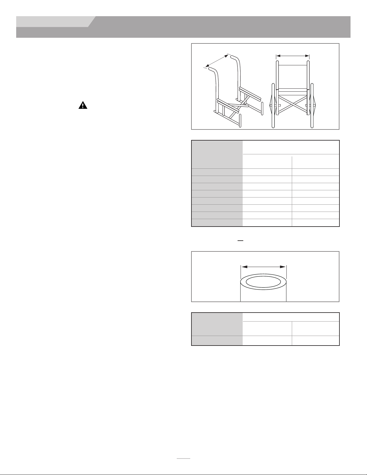
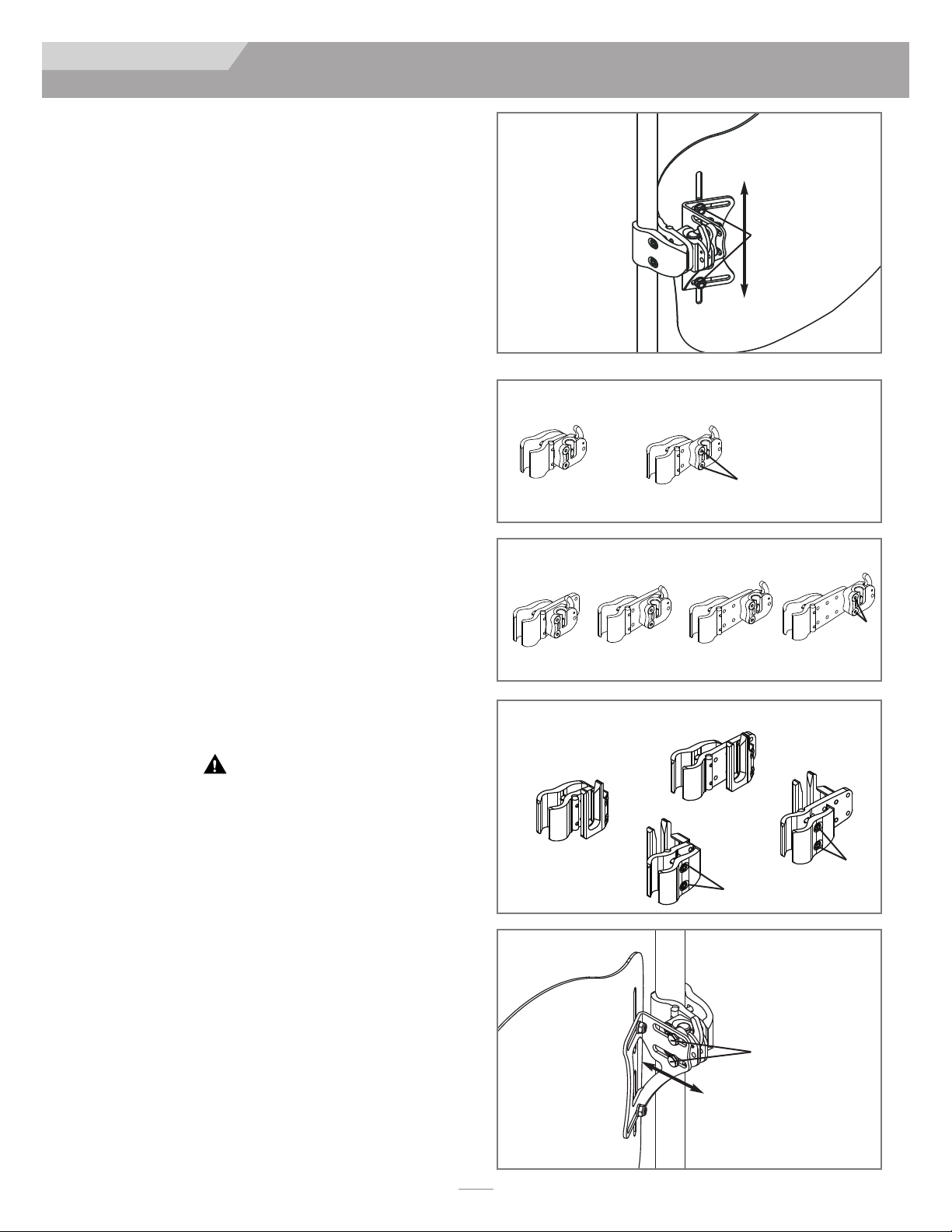
2. Visually determine the desired location of the receivers on
the wheelchair’s back canes. The mounting hardware should
be at approximately equal heights on each back post (Fig. 3)
and parallel to the seat frame (Fig. 4). Higher locations on the
back canes are generally better.
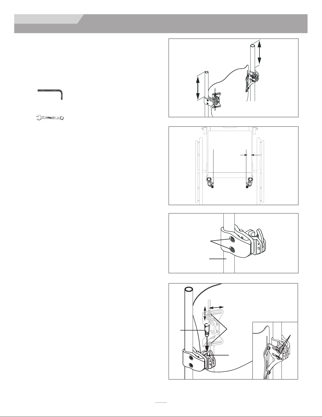
3. Attach the hardware receivers. (Fig. 5)
a. Loosen the clamp screws (A) with the enclosed 4mm hex
key. NOTE– For large tube diameters, clamp screws may
have to be removed completely.
b. Attach and align receiver to the wheelchair back canes (B).
c. Hand tighten clamp screws (A). NOTE– Receivers may
require additional lateral adjustment to ensure proper
alignment.
Attaching and Aligning the J3 Back Shell (Fig. 6)
a. Loosen bracket nuts (C) and mounting pin bolts (F) using
10mm box-end wrench until hardware can move easily in
all directions.
b. Attach the 3 Back to the hardware receivers by inserting
left and right mounting pins (D) in the left and right
receivers (E).
c. Locate back to the approximate location, relative to both
chair and user.
d. Tighten bolts on the inside of the mounting pin (F). The
recommended torque specification is 100 - 110 in-lbs.
(11.3 - 12.4 Nm). NOTE– Back depth and angle may
require additional adjustment to ensure proper fit to the
user.
e. Tighten bracket nuts (C). The recommended torque
specification is 75 - 85 in-lbs. (8.5 - 9.3 Nm). NOTE–
Back height may require additional adjustment to ensure
proper fit to the user.
f. Test back release by pressing the release levers forward
and removing the back off the chair. (See Removal and
Replacement section for further details.) Proper align-
ment of the mounting hardware and back is achieved
when smooth attachment and release can be easily done.
g. If proper alignment has not been achieved, adjust the
components until properly aligned.
h. Once properly aligned, tighten the hardware receiver
clamp screws. The recommended torque specification is
75 - 85 in-lbs (8.5 - 9.3 Nm).
Figure 3
Figure 4
Figure 5
parallel
A
B
C
height width
E
D
Figure 6
F

103721 Rev. E
7
ENGLISH
INSTALLATION
ATTACHING FOUR POINT HARDWARE
(OPTIONAL) (FIG. 7, 8, 9)
Tools required (included with J3 Back with 4-Point
Hardware)
• 4mm hex key
• 10mm box end wrench
• 5/8" box end wrench
Installing the 4-Point Hardware
1. Loosen the clamp screws (A) with the supplied 4mm hex key
and slip the clamps around the Back Canes (B).
2. The mounting hardware should be at equal heights on each
back post (Fig. 8) and parallel to the seat frame (Fig. 7).
3. Hand tighten clamp screws (A). Loosen bracket nuts (C) and
Mounting Pin bolts (F) using the supplied 10mm box-end
wrench until hardware can move easily in all directions
NOTE– For large tube diameters, clamp screws may have to be removed
completely.
4. Attach the 3 Back by inserting left and right Mounting Pins
(D) in the left and right Latch Receivers (E).
5. Install back to the approximate location, relative to both
chair and user.
6. Tighten bolts on the inside of the Mounting Pin (F). Torque
to 100 - 110 in-lbs.(11.3 - 12.4 Nm).
NOTE– Receivers may require additional lateral adjustment to ensure proper
alignment.
7. Tighten bracket nuts (C). Torque to 75 - 85 in-lbs. (8.5 - 9.3
Nm).
NOTE– Back height may require additional adjustment to ensure proper fit
to the user.
8. Test back release by pressing the release levers (L) forward
and removing the back off the chair. Proper alignment of the
mounting hardware and back is achieved when smooth
attachment and release can be easily done.
9. If proper alignment has not been achieved, adjust the com-
ponents until properly aligned.
10. Once properly aligned, tighten the hardware receiver clamp
screws (A). Torque to 75 - 85 in-lbs (8.5 - 9.3 Nm)
11. Loosen bolts (G) to install Lower Receivers on Back Canes
(H).
12. Use a 5/8" end wrench to loose the nut (K) that secures the
Lower Mounting Pin (I) so that it slides fore and aft.
13. Slide lower receiver up ( ) until it surrounds the Lower
Mounting Pin (I).
NOTE– Leave 1/8" to 1/4" of space between the bottom of the Lower
Mounting in (I) and the bottom of the Lower Receiver Channel (J).
NOTE– Make sure the Upper Mounting Bracket and Lower Receiver Bracket
are in alignment on the Back Canes. Misalignment of the brackets
may result in impaired function of quick-release.
14. Once properly aligned, tighten the hardware receiver clamp
screws (G). The recommended torque specification is 75 -
85 in-lbs (8.5 - 9.3 Nm). Then tighten the Lower Mounting
Pin nut (K). Torque to 100 - 110 in-lbs.(11.3 - 12.4 Nm).
PARALLEL
Figure 7
Figure 8
E
L
C
A
BF
D

103721 Rev. E 8
ENGLISH
INSTALLATION
15. Test back release by pressing the release levers (L) forward
and removing the back off the chair. (See Removal and
Replacement section for further details.) Proper alignment of
the mounting hardware and back is achieved when smooth
attachment and release can be easily done.
16. If proper alignment has not been achieved, adjust the compo-
nents until properly aligned.
17. To make micro adjustments, loosen bolts C and F. This will
allow for minor changes in height, depth and angle. Retighten
all bolts to required specs and test back function and quick-
release.
18. Or, to make macro adjustments, loosen, but do not remove,
bolts G, C and F (Figs. 8, 9). Position backrest to desired
height, depth and angle.
19. Retighten all bolts to required specs and test back function
and quick-release.
Adjusting the Four-Point Hardware
To make micro adjustments, loosen bolts C and F. This will allow
for minor changes in height, depth and angle. Retighten all bolts to
required specs and test back function and quick-release.
Or, to make make macro adjustments, loosen, but do not remove,
bolts G, C and F (Figs. 8, 9). Position backrest to desired height,
depth and angle. Retighten all bolts to required specs and test back
function and quick-release.
INSTALLING THE LITE MOUNT
HARDWARE (FIG. 10, 11)
1. Loosen bolt (A) in each bracket.
2. Slide all four brackets onto backrest frame tubes (B).
NOTE– All Lite Mount Hardware ships with optional spacers (C) to be used
as needed on back posts smaller than one inch in diameter.
3. Install backrest onto Lite Mount Hardware using bolt (D).
4. Adjust height and position of backrest and tighten.
NOTE– On backrest frame tubes with permanently attached or formed push
handles, the back frame tubes may need to be removed and the
mounting hardware slid on from the bottom.
Figure 9
J
L
I
G
J
Figure 10
Figure 11
A
D
B
C

103721 Rev. E
9
ENGLISH
ADJUSTMENT
ADJUSTING J3 HEIGHT, DEPTH AND
ANGLE
The first phase of the 3 Back hardware installation is complete. It
is now the appropriate time to have the user seated back in the
chair for personalizing the 3 Back. Do not have the user apply full
pressure on the back as it is not fully tightened to the full torque
requirements.
1. Height Adjustment (Fig. 12)
a. With the user in the chair, identify the desired height of the
back. Once identified, have the user remove pressure from
the 3 Back by leaning or sliding partially forward if possible
to allow the adjustment to take place.
b. Loosen the bracket nuts (A) and adjust the height of the back
shell to required position.
c. Securely tighten the bracket nuts (A). The recommended
torque specification is 75-85 in-lbs. (8.5 - 9.3 Nm).
NOTE– After height adjustment is complete, check that the width was not
inadvertently changed.
2. Depth/Angle Adjustment (Figs. 13, 14, 15, 16)
Please note there are two types of hardware that can be ordered–
standard hardware (Fig. 13) or the longer, adjustable hardware (Fig.
14). Both sets of hardware are adjusted the same, but the standard
hardware allows for 2 inches of depth adjustment (Fig. 13) while
the extended hardware (adjustable hardware) allows for a total of
3.4 inches of depth adjustability (Fig. 14).
a. To adjust 3 Back depth and angle loosen left and right bolts
(Fig. 16-B) on bracket slots.
b. Adjust depth and/or angle and securely tighten. The recom-
mended torque specification is 100-110 in-lbs. (11.3 - 12.4
Nm). Ensure that none of the depth adjustment nuts (Fig 16-B)
will slip or rotate.
c. If additional depth is needed, remove back from receivers.
Remove screws (Figs. 13-D, 14-D) from receiver using the
enclosed 4mm hex key, and reposition to desired depth.
Tighten screws to 25-35 in-lbs. (2.8 - 4 Nm).
WARNING
Ensure that all hardware has been properly tightened
once all adjustments have been completed and the J3
Back is ready for use.
Figure 12
Standard hardware– 2 depth settings
Depth 1 Depth 2
Figure 13
A
D
Four-Point Hardware
Lower Receivers
Figure 15
Figure 16
B
Depth 1 Depth 2 Depth 3 Depth 4
Extended (Adjustable) hardware Figure 14
D
D
D

103721 Rev. E 10
ENGLISH
ACCESSORIES
VANITY FLAP INSTALLATION
1. Lift upper flap of 3 Back Cover (Fig. 17)
2. Match hook to loop and attach Vanity Flap to the back of the
3 Back Cover (Fig. 17). Reposition upper flap of cover to
sandwich the Vanity Flap between the flaps the upper and
lower flaps (Fig. 18).
3. Remove Seat Cushion from wheelchair and sandwich “tail” of
Vanity Flap between wheelchair support surface and Seat
Cushion (Fig 20).
4. Adjust Vanity Flap as necessary by moving the tail in or out
from under the Seat Cushion. If necessary the upper part of
the vanity flap can be moved up or down on the Seat Back
also.
5. Insert Hook & Loop Wrap ties through the appropriate
grommets on the Vanity Flap, then wrap around the wheel-
chair frame and insert the leading end through the slot end of
the Wrap (Fig. 21). Snug up and close outside gaps in Vanity
Flap (Fig. 22).
Figure 17 Figure 18
Figure 19 Figure 20
Figure 21 Figure 22
Figure 23
Finished J3 Vanity Flap Installation

103721 Rev. E
11
ENGLISH
ACCESSORIES
SPINE ALIGN POSITIONING
COMPONENTS
Spine Align Positioning Components are designed to provide inti-
mately shaped support within an “off-the-shelf” back. (Depending
on your market, Spine Align components may be included with your
back.) To install Spine Align please read the following directions.
1. Spine Align Positioning Component Installation
a. Have the user remove pressure from the 3 Back by leaning
or sliding partially forward if possible.
b. Release Velcro strip on the top cover flap (Fig. 24) and lift
the cover forward to reveal the inside of the 3 Back.
c. Place the positioning component(s) on the Velcro inside of
the shell (Fig. 25) and reattach the top cover flap. Pull down
making certain that the top seam is aligned with the top of
the shell. If seam does not line up, the bottom of the cover
may need to be loosened (Fig. 26).
d. Have the user test the current Spine Align setup for comfort
and support and repeat steps a-c until adjustment is complete.
e. Multiple configurations and combinations of Spine Align com-
ponents can be used. If additional Spine Align shapes or sizes
are required, please contact your dealer or Sunrise Medical
at 800-333-4000.
NOTE– If you require further information on the J3 Spine Align system,
please review our animation at www.sunrisemedical.com.
Installation of the 3 back is complete.
J3 ACCESSORIES
If you have ordered 3 accessories such as laterals, headrests or
harnesses please consult the installation instructions related to
those items.
Positioning Components
Large Lumbar
Small Lumbar
Wedge
Curved Shim
Flat Shim
Posterior/Lateral Pelvic
Lateral Shim
Large Bean Bag
Small Bean Bag
Figure 24
Figure 25
Figure 26
Velcro
Top cover
flap
Top cover flap
Top seam
Cover
Spine Align
components

103721 Rev. E 12
ENGLISH
TRANSIT SAFETY
BAC TRANSIT SAFETY
The 3 back has been dynamically tested for use in a motor vehicle.
Please follow all installation, use and maintenance instructions with-
in this manual as well as the transit instructions listed below.
WARNINGS
1. If possible and feasible, the rider should transfer to the
Original Equipment Manufacturer vehicle seat and use
the vehicle restraints.
2. he distance between the top of the user’s shoulder and
the top of the back should not exceed 6.5" (16.5 cm).
3. he wheelchair must be labeled as appropriate for use
as a seat in a motor vehicle, dynamically tested to the
performance requirements of ISO Standard 7176-19
and installed, used and maintained according to the
manufacturer’s instructions.
4. If the original wheelchair seat was replaced, the new seat
must be approved for wheelchair transit, installed and
used as indicated in the manufacturer’s instructions.
5. he Wheelchair iedown and Occupant Restraint
System (W ORS) should be compatible with the spe-
cific wheelchair, used as indicated in the manufactur-
er’s instructions and should comply with the perform-
ance requirements of ISO Standard 10542.
6. he wheelchair must be forward facing during transport.
7. In order to reduce the potential of injury to vehicle
occupants wheelchair-mounted accessories such as
trays and respiratory equipment should be removed
and secured separately.
8. his product is intended for use by adults ranging in
weight from 79 to 300lbs or up to 500 lbs. (227 kg) for
widths over 22".
9. Postural support devices such as pelvic positioning
belts, anterior trunk supports or postural supports
such as lateral trunk supports should not be relied on
for occupant restraint in a moving vehicle unless they
are labeled as conforming to ISO Standard 16840-4.
10. Alterations or substitutions should not be made to the
structure, parts or components, without consulting the
manufacturer.
11. Backshell mounting bracket must be attached in the
“leg up” position for transit use. (See below.) Refer to
the appropriate section for correct back hardware
mounting instructions.
WARNING
FAILURE TO HEED THESE WARNINGS
COULD CAUSE SEVERE INJURY TO THE
WHEELCHAIR RIDER OR OTHERS.
Correct bracket
orientation for transit
Top of back
Incorrect bracket
orientation for transit

103721 Rev. E
13
ENGLISH
REMOVAL AND REPLACEMENT
Removal
Following installation and adjustment, the back can be easily
removed from the wheelchair if necessary. To remove, push each
release lever forward to unlock (Fig. 27). Once both levers are in
the forward position, simply lift the back straight up (Fig. 28) using
the handle located on the top of the back.
Proper reattachment after removal
To reattach the back to the hardware receivers, simply line up the
pins to the receivers and push into place (Fig. 28). If properly
inserted the pins will “click” to a locked position.
WARNING
If you are uncertain if you have heard the locking
“click”, pull up on the back using the handle to ensure
that it has been securely locked.
Locking Pins (Fig. 30)
The 3 Back comes with two locking pins which, when secured,
prevent the back from being released from the chair. To lock, insert
the pins (A) into the mounting receivers (B). Simply remove the
pins if the quick-release capability is desired.
WARRANTY
Claims and repairs should be processed through the nearest
authorized supplier. Except for express warranties made herein, all
other warranties, including implied warranties of merchantability
and warranties of fitness for a particular purpose are excluded.
There are not warranties which extend beyond the description on
the face hereof. Remedies for breach of express warranties herein
are limited to repair or replacement of the goods. In no event shall
damages for breach of any warranty include any consequential
damages or exceed the cost of non-conforming goods sold.
24 MONTH LIMITED WARRANTY
Each ay 3 Back is carefully inspected and tested to provide peak
performance. Every ay 3 Back is guaranteed to be free from
defects in materials and workmanship for a period of 24 months
from the date of purchase, provided normal use. Should a defect in
materials or workmanship occur within 24 months from the origi-
nal date of purchase, Sunrise Medical will, at its option, repair or
replace it without charge. This warranty does not apply to punc-
tures, tears or burns, nor to the back’s removable cover.
Figure 27
Figure 29 Figure 30
Figure 28
A
B
REMOVAL AND REPLACEMENT

103721 Rev. E 14
ESPAÑOL
INTRODUCCIÓN
Sunrise Medical recomienda consultar con un médico o un
terapeuta experimentado en posicionamiento para determi-
nar si es apropiada la utilización del respaldo J3. Los respal-
dos sólo deben ser instalados por un proveedor autorizado
de Sunrise Medical.
RESPALDO DE JAY J3
El Respaldo de ay 3 está diseñado para proporcionar, un apoyo
apropiado para la espalda a una gran variedad de usuarios. Está dis-
eñado para proporcionar un apoyo simple, confortable y efectivo
para ayudar a maximizar su funcionalidad e incrementar la toleran-
cia a la silla. Además, es ligero, duradero y fácil de utilizar.
Peso máximo del usuario:
300 lbs. (136 kg).
500 lbs. (227 kg) para anchos de 22 pulg., 24 y 26 pulg.
ADVERTENCIA
Instalar un soporte para la espalda en una silla de ruedas
puede afectar al centro de gravedad de la misma y puede
provocar que la silla de ruedas se vuelque hacia atrás,
provocando posibles lesiones.
Evalúe siempre la necesidad de instalar en la silla de
ruedas tubos antivuelcos o abrazaderas adaptadoras del
eje para amputados para ayudar a aumentar la estabilidad.
ADVERTENCIA
No utilice el Respaldo J3 para empujar o levantar la silla de
ruedas. El uso inapropiado puede provocar que el respaldo
se desprenda inesperadamente de la silla de ruedas.
ADVERTENCIA
No utilice la empuñadura del respaldo J3 para levantar
la silla de ruedas. Esta empuñadura sólo está diseñada
para la extracción del respaldo.
RESPALDO DE J3
MID THORACIC (MT)
LOWER THORACIC (LT)
MID THORACIC (MT)
UPPER THORACIC (UT)
SHOULDER HEIGHT (SH)
POSTERIOR
POSTERIOR AND DEEP LATERALS POSTERIOR DEEP CONTOUR
POSTERIOR AND LATERALS
Standard Hardware
Four Point Hardware
Lite Mount Hardware
Four Point Extended
(Adjustable) Hardware
Extended (Adjustable)
Hardware
Torácica media (ejemplo)
Funda
Trasero Trasero
lateral Trasero lateral
profundo Trasero contorno
profundo
Torácica baja Torácica media Torácica alta Altura de
hombros
Sistema de fija-
ciones estándar
Accesorios de cuatro
puntos (estándar)
Sistema de fijaciones
extensibles (ajustable)
Accesorios de cuatro
puntos extensibles
(ajustable)
Accesorios de mon-
taje ligero (Lite)
SH
UT
MT
LT
Base de
espuma
Estructura
del respaldo
Llave hexagonal de
4 mm Llave de estrías
común de 10 mm
Clavija de ajuste

103721 Rev. E
15
ESPAÑOL
MANTENIMIENTO Y LIMPIEZA
ESPECIFICACIONES DE MANTENIMIENTO
Y AJUSTE DE LAS FIJACIONES
Sunrise recomienda que todas las fijaciones sean comprobadas por
si están desgastadas y para comprobar si hay, por ejemplo, pernos
sueltos o componentes rotos, cada 6 meses. Las fijaciones sueltas
deben volver a apretarse de acuerdo con las instrucciones de insta-
lación. Todas las abrazaderas deben ajustarse de acuerdo con las
especificaciones de ajuste, según lo estipulado en la sección de
instalación del sistema de fijaciones. Póngase en contacto con su
proveedor autorizado de Sunrise Medical inmediatamente para
sustituir cualquier componente roto. No continúe utilizando el sis-
tema después de identificar componentes sueltos o rotos.
FÁCIL DE LIMPIAR
NOTE– Al desmontar el respaldo para realizar la limpieza, fíjese bien en la
posición de los componentes de alineación vertebral con Velcro®
para montarlos correctamente después.
Para limpiar la funda del respaldo
Retire la funda despegando el Velcro. Separe la funda de la estructura
del respaldo. Localice el cierre de la parte inferior de la funda y
ábralo. Retire la espuma y ponga la funda al revés. Cierre la cre-
mallera de la funda y evite que se enganche. Lave a máquina con agua
templada (50°C). Seque al natural o a máquina a baja temperatura.
NOTA: No limpie las fundas en tintorería ni use lavadoras y secadoras
industriales. No las meta en autolavado de vapor. No use cloro.
Vuelva a colocar la espuma dentro de la funda. Tenga en cuenta que
la base contiene dos capas de espuma. Al volver a colocar la
espuma, compruebe que la capa más delgada de color “gris
claro”quede mirando hacia la estructura del respaldo. Una vez que
la espuma esté perfectamente colocada dentro de la funda, cierre
la cremallera para finalizar.
Para limpiar la estructura del respaldo
La estructura se puede limpiar mediante un paño humedecido con
agua y jabón. No se requiere ningún otro mantenimiento.
Para limpiar los componentes de posicionamiento
Los componentes de posicionamiento pueden limpiarse con agua y
jabón. No sumerja los componentes de posicionamiento en agua.
Si tiene dudas acerca del procedimiento de limpieza, comuníquese
con un representante autorizado de Sunrise Medical.
Símbolos para el cuidado en el lavado
Lavar a máquina en agua tibia
(50° C)
Utilizar sólo lejía sin cloro, en
casos necesarios
Secar al natural
No planchar
No lavar en seco

103721 Rev. E 16
ESPAÑOL
COLOCACIÓN DEL RESPALDO EN LA SILLA
COMPATIBILIDAD
Tipos de sillas de ruedas
El Respaldo 3 está diseñado para ser compatible con la mayoría de
las sillas de ruedas con las siguientes excepciones:
No deben utilizarse sillas de ruedas que sean ajustables angular-
mente, reclinables o basculantes, y que lleguen a un ángulo mayor
de 60 grados.
ADVERTENCIA
Utilizar estos tipos de silla de ruedas puede hacer que
el respaldo se suelte accidentalmente de la silla de
ruedas, provocando una caída y una posible lesión.
Dimensiones de la silla de ruedas
El Respaldo 3 está diseñado para sustituir la tapicería de la parte
posterior de la silla de ruedas. Antes de la instalación determine si
la silla de ruedas utilizada tiene tubos posteriores compatibles,
midiendo la anchura entre ambos tubos, como se ve en la Figura 1.
Luego, con esa medida, consulte la Tabla 1 que aparece a contin-
uación para ver si los tubos posteriores son de la anchura correcta.
Después, compruebe que los tubos posteriores son de un diámetro
compatible (Tabla 2). Las piezas de fijación del respaldo 3 pueden
montarse en tubos posteriores de sillas de ruedas entre 3/4" y 1
1/8". Mida el diámetro del tubo trasero (Fig. 2) y consulte la Tabla 2
para asegurarse de que los tubos posteriores son compatibles.
Si no puede determinar que los tubos posteriores sean compati-
bles, póngase en contacto con su proveedor autorizado de Sunrise
Medical o con el servicio de atención al cliente de Sunrise Medical.
Anchura del
respaldo J3*
(todos los contornos)
Anchura de los tubos posteriores
medidos desde las caras externas de
los tubos (Fig. 1-A)
Anchura mínima Anchura máxima
pulg. cm pulg. cm
12" 11.7 29.7 14.3 36.3
14" 13.7 34.9 16.3 41.3
16" 15.7 40.0 18.3 46.4
18" 17.7 45.1 20.3 54.5
20" 19.7 50.1 22.3 56.5
22" 21.7 55.1 24.3 61.7
24" 23.7 60.2 26.3 66.8
26" 25.7 65.3 28.3 71.9
Figura 2
B
Anchura del
respaldo J3*
(todos los contornos)
diámetro de tubos posteriores
(Fig. 2-B)
Anchura mínima Anchura máxima
pulg. cm pulg. cm
12" - 26" 3/4 1.9 1 1/8 2.85
Tabla 2
Tabla 1
Figura 1
AA
* La anchura del respaldo está identificada en el número de serie
del respaldo. Ejemplo: 3PAMTS14SH es un respaldo de 14".

103721 Rev. E
17
ESPAÑOL
INSTALACION
INSTALACIÓN DE LAS PIEZAS DE
FIJACIÓN Y MONTAJE
Por favor lea las siguientes instrucciones antes de dar comienzo a la
instalación.
Para instalar el respaldo 3, es mejor comenzar sin el usuario en la
silla de ruedas. Una vez que el respaldo está instalado, y sólo se
necesitan hacer pequeños ajustes, el usuario podrá volver a sen-
tarse en la silla de ruedas.
Herramientas necesarias (incluidas con el respaldo J3)
• Llave hexagonal de 4 mm
• Llave de estrías común de 10 mm
Instrucciones para la instalación de las piezas de fijación
(Figs. 3, 4, 5)
1. Retire el respaldo existente de la silla de ruedas siguiendo las
instrucciones del fabricante.
2. Determine visualmente la ubicación deseada de los recep-
tores en los tubos posteriores de la silla de ruedas. Las piezas
del sistema de fijación deben estar montadas a una altura
equidistante en cada tubo posterior (Fig. 3) y paralelas al
armazón del asiento (Fig. 4). Cuanto más alta la ubicación de
los tubos posteriores, mejor.
3. Inserte los receptores del sistema de fijación. (Fig. 5)
a. Afloje los tornillos de la abrazadera (A) con la llave hexag-
onal de 4 mm incluida.
NOTA: ara tubos de mayor diámetro, quizá sea necesario extraer totalmente
los tornillos de la abrazadera.
b. Inserte y alinee el receptor a los tubos posteriores de la
silla de ruedas (B).
c. Ajuste los tornillos de la abrazadera a mano (A). NOTA:
Es posible que los receptores necesiten ajuste lateral adi-
cional para garantizar la alineación apropiada.
Inserción y alineación de la estructura del respaldo J3 (Fig. 6)
1. Afloje las tuercas de los soportes (C) y los pernos de la clavija
de montaje (F) utilizando la llave de estrías común de 10 mm
hasta que las piezas del sistema de fijación se deslicen fácil-
mente en todas direcciones.
2. Inserte el respaldo 3 en los receptores del sistema de
fijación colocando las clavijas de montaje izquierda y derecha
(D) en los receptores izquierdo y derecho (E).
3. Coloque el respaldo en la posición deseada aproximada, en
relación con el usuario y con la silla.
4. Ajuste los pernos interiores de la clavija de montaje (F). La tor-
sión de ajuste recomendada es de 100 - 110 pulg-lbs (11,3 -
12,4 Nm). NOTA: Es posible que la profundidad y el ángulo
del respaldo necesiten un ajuste adicional para garantizar una
posición adecuada para el usuario.
5. Ajuste las tuercas (C). La torsión de ajuste recomendada es
de 75 - 85 pulg-lbs (8,5 - 9,3 Nm). NOTA: Es posible que la
altura del respaldo necesite un ajuste adicional para garanti-
zar una posición adecuada para el usuario.
6. Compruebe es istema de extracción del respaldo presionan-
do las palancas de liberación hacia delante y quitando el
respaldo de la silla. (Para más información, consulte la sección
Retirada y nueva colocación). La alineación de las piezas de
ajuste, montaje y respaldo será correcta si la instalación y la
liberación pueden realizarse fácilmente.
7. Si no se ha conseguido una alineación apropiada, ajuste los
componentes hasta que queden correctamente alineados.
8. Una vez bien alineados, ajuste los tornillos de la abrazadera
del receptor. La torsión de ajuste recomendada es de 75 - 85
pulg-lbs (8,5 - 9,3 Nm).
Figura 3
Figura 5
A
B
Figura 4
paralelo
C
altura anchura
E
D
Figura 6
F

103721 Rev. E 18
ESPAÑOL
INSTALACION
FIJACIÓN DE LOS ACCESORIOS DE CUA-
TRO PUNTOS (OPCIONAL) (FIG. 7, 8, 9)
Herramientas necesarias (incluidas con el respaldo J3 con
accesorios de 4 puntos)
• Llave hexagonal de 4 mm
• Llave de caja de 10 mm
• Llave de caja de 5/8 pulg.
Instalación de los accesorios de 4 puntos
1. Afloje los tornillos de las abrazaderas (A) con la llave hexago-
nal de 4 mm incluida, y deslice las abrazaderas alrededor de
los bastones del respaldo (B).
2. Los accesorios de montaje deben tener la misma altura en
cada uno de los postes posteriores (Fig. 8) y deben estar
paralelos a los costados del bastidor del asiento (Fig. 7).
3. Apriete los tornillos de las abrazaderas (A) con la mano.
Afloje las tuercas de mariposa (C) y los pernos del pasador de
montaje (F) con la llave de caja de 10 mm incluida, hasta que
los accesorios se muevan fácilmente en cualquier dirección.
NOTA: En caso de tubos de mayor diámetro, es probable que deban reti-
rarse por completo los tornillos de las abrazaderas.
4. Coloque el cojín 3 instalando los pernos del pasador de
montaje (D) izquierdo y derecho en los receptáculos del
seguro izquierdo y derecho (E).
5. Instale el respaldo en su ubicación aproximada, en relación al
usuario y a la silla de ruedas.
6. Apriete los pernos en la parte interna del pasador de montaje
(F). Use un parámetro de tensión de 100 a 110 pulg.-lbs.
(11,3 – 12,4 Nm).
NOTA: Es posible que los receptáculos requieran ajustes laterales adi-
cionales para garantizar una alineación correcta.
7. Apriete las tuercas de mariposa (C). Use un parámetro de
tensión de 75 a 85 pulg.-lbs. (8,5 a 9,3 Nm).
NOTA: Es posible que deba realizar ajustes adicionales a la altura del
respaldo para permitir una adaptación apropiada al usuario.
8. Compruebe el mecanismo de liberación del respaldo oprim-
iendo las palancas de liberación (L) hacia delante y retirando
el respaldo de la silla. Se obtiene una alineación correcta de
los accesorios de montaje y el respaldo cuando éste último
puede fijarse y retirarse sin problemas.
9. Si no obtiene una alineación adecuada, ajuste los compo-
nentes hasta que queden alineados correctamente.
10. Una vez que estén alineados correctamente, apriete los
tornillos de la abrazadera receptora (A). Use un parámetro
de tensión de 75 a 85 pulg.-lbs. (8,5 – 9,3 Nm).
11. Afloje los pernos (G) para instalar los receptáculos inferiores
en los bastones (H).
12. Utilice una llave de caja de 5/8 pulg. para aflojar la tuerca (K)
que asegura el pasador de montaje inferior (I) para deslizarlo
hacia delante y atrás.
PARALLEL
Figure 7
Figure 8
E
L
C
A
BF
D
PARALELOS

103721 Rev. E
19
ESPAÑOL
INSTALACION
13. Deslice el receptáculo inferior hacia arriba ( ) hasta que se
encuentre alrededor del pasador de montaje inferior (I).
NOTA: Deje un espacio de 1/8 a 1/4 pulg. (3 mm a 6 mm) entre la parte
de abajo del pasador de montaje inferior (I) y la parte de abajo del
canal receptor inferior (J).
NOTA: Cerciórese que la abrazadera de montaje superior y la abrazadera
receptora inferior estén alineadas con los bastones. Una mala alin-
eación de las abrazaderas puede ocasionar problemas de la función
de liberación rápida.
14. Una vez que estén alineadas correctamente, apriete los
tornillos de la abrazadera receptora (G). Los parámetros de
tensión recomendada son de 75 a 85 pulg.-lbs. (8,5 a 9,3
Nm). Enseguida apriete la tuerca del pasador de montaje
inferior (K). Use un parámetro de tensión de 100 a 110
pulg.-lbs. (11,3 – 12,4 Nm).
15. Compruebe el mecanismo de liberación del respaldo oprim-
iendo las palancas de liberación (L) hacia delante y retirando
el respaldo de la silla. (Consulte la sección Retirada y Nueva
Colocación para conocer los detalles.) Se obtiene una alin-
eación correcta del accesorio de montaje y del respaldo
cuando éste último puede fijarse y retirarse sin problemas.
16. Si no obtiene una alineación adecuada, ajuste los compo-
nentes hasta que queden alineados correctamente.
17. Para realizar los ajustes finos, afloje los pernos C y F. De esta
manera puede hacer modificaciones menores en la altura,
profundidad y ángulo. Vuelva a apretar los pernos según las
especificaciones requeridas y compruebe la función del
respaldo y de liberación rápida.
18. O bien, para realizar ajustes mayores, afloje los pernos G, C
y F (Fig. 8, 9), teniendo cuidado de no retirarlos. Coloque el
respaldo a la altura, profundidad y ángulo deseados.
19. Vuelva a apretar los pernos según las especificaciones requeri-
das y compruebe la función del respaldo y de liberación rápida.
Ajuste de los accesorios de cuatro puntos
Para realizar los ajustes finos, afloje los pernos C y F. De esta manera
puede hacer modificaciones menores en la altura, profundidad y ángu-
lo. Vuelva a apretar los pernos según las especificaciones requeridas y
compruebe la función del respaldo y de liberación rápida.
O bien, para realizar ajustes mayores, afloje los pernos G, C y F
(Fig. 8, 9), teniendo cuidado de no retirarlos. Coloque el respaldo a
la altura, profundidad y ángulo deseados. Vuelva a apretar los per-
nos según las especificaciones requeridas y compruebe la función
del respaldo y de liberación rápida.
INSTALACIÓN DE LOS ACCESORIOS DE
MONTAJE LIGERO (LITE) (FIG. 10, 11)
1. Afloje el perno (A) en cada abrazadera.
2. Deslice las cuatro abrazaderas en los tubos del bastidor del
respaldo (B).
NOTA: Todos los accesorios de montaje ligero (Lite) se envían con espaci-
adores (C) opcionales para ser utilizados como sea necesario en los
postes traseros que sean menores de una pulgada (2,54 cm) de
diámetro.
3. Instale el respaldo en los accesorios de montaje ligero uti-
lizando los pernos (D).
4. Ajuste la altura y la posición del respaldo y apriete los pernos.
NOTA: En tubos del bastidor del respaldo con asideros de empuje moldead-
os o fijos permanentemente, deberá retirar los tubos del bastidor y
deslizar los accesorios de montaje desde la parte inferior.
Figure 10
Figure 11
A
D
B
C
Figure 9
J
L
I
G
J

103721 Rev. E 20
ESPAÑOL
AJUSTE
AJUSTE DE ALTURA, PROFUNDIDAD Y
ÁNGULO EN J3
La primera fase de la instalación de las piezas de ajuste del respaldo
3 está completa. Es el momento de sentar al usuario en la silla para
personalizar la posición del respaldo 3. No permita que el usuario
ejerza demasiada presión sobre el respaldo, ya que no está ajustado
totalmente según las especificaciones de torsión.
1. Ajuste de altura (Fig. 12)
a. Con el usuario sentado en la silla, seleccione la altura deseada
del respaldo. Una vez seleccionada, solicite al usuario que
aligere la presión sobre el respaldo, incorporándose o
deslizándose parcialmente hacia delante, para poder llevar a
cabo el ajuste final.
b. Afloje las tuercas del soporte (A) y ajuste la altura de la
estructura del respaldo en la posición deseada.
c. Ajuste con firmeza las tuercas del soporte (A). La torsión de
ajuste recomendada es de 75 - 85 pulg-lbs (8,5 - 9,3 Nm).
NOTA: Cuando haya completado el ajuste de altura, compruebe que la
anchura no se haya modificado inadvertidamente.
2. Ajuste de ángulo y profundidad (Figs. 13, 14, 15, 16)
Tenga en cuenta que puede solicitar dos tipos de piezas del sistema
de fijación: las estándar (Fig. 13) o las piezas más largas y ajustables
(Fig. 14). Ambos juegos de piezas se ajustan de la misma manera,
pero las estándar sólo permiten dos pulgadas de ajuste de profundi-
dad (Fig. 13) mientras que las piezas extensibles (o ajustables) per-
miten un total de 3,4 pulgadas de ajuste de profundidad (Fig. 14).
a. Para ajustar la profundidad y el ángulo del respaldo 3, afloje
los pernos izquierda y derecha (Fig. 16-B) de las ranuras del
soporte.
b. Ajuste la altura y/o el ángulo y fíjelos con firmeza. La torsión
de ajuste recomendada es de 100 - 110 pulg-lbs (11,3 - 12,4
Nm). Compruebe que ninguna de las tuercas de ajuste de
profundidad (Fig 16-B) se deslicen o roten.
c. Si se necesita más profundidad, retire el respaldo de los
receptores. Retire los tornillos (Figs. 13-D, 14-D) del recep-
tor utilizando la llave hexagonal de 4 mm incluida, y vuelva a
ubicarlos a la profundidad deseada. Ajuste los tornillos a 25-
35 pulg-lbs. (2,8 - 4 Nm).
ADVERTENCIA
Compruebe que todas las piezas de fijación se han insta-
lado adecuadamente una vez que todos los ajustes se
hayan completado y el respaldo J3 estará listo para ser
utilizado.
Figura 12
A
Figura 16
B
Piezas del sistema de fijación estándar:
2 configuraciones de profundidad
Profundidad 1 Profundidad 2
Figura 13
D
Profundidad 1 Profundidad 2 Profundidad 3 Profundidad 4
Figura 14
D
Piezas del sistema de fijación extensibles
(Ajustable)
Figure 15
D
D
Accesorios de cuatro puntos
Receptáculos inferiores
Other manuals for J3 BACK
5
Table of contents
Languages:
Other Jay Wheelchair manuals

Jay
Jay J3 BACK User manual

Jay
Jay J3 BACK User manual

Jay
Jay WHITMYER PRO User manual

Jay
Jay FIT 2U BACK User manual

Jay
Jay J3 PLUS Back User manual

Jay
Jay Fusion User manual

Jay
Jay Fusion Configuration guide

Jay
Jay Shape Back User manual

Jay
Jay J2 Plus Installation and operation manual

Jay
Jay Union User manual