8
1 2 3
ESPAÑOL
ab
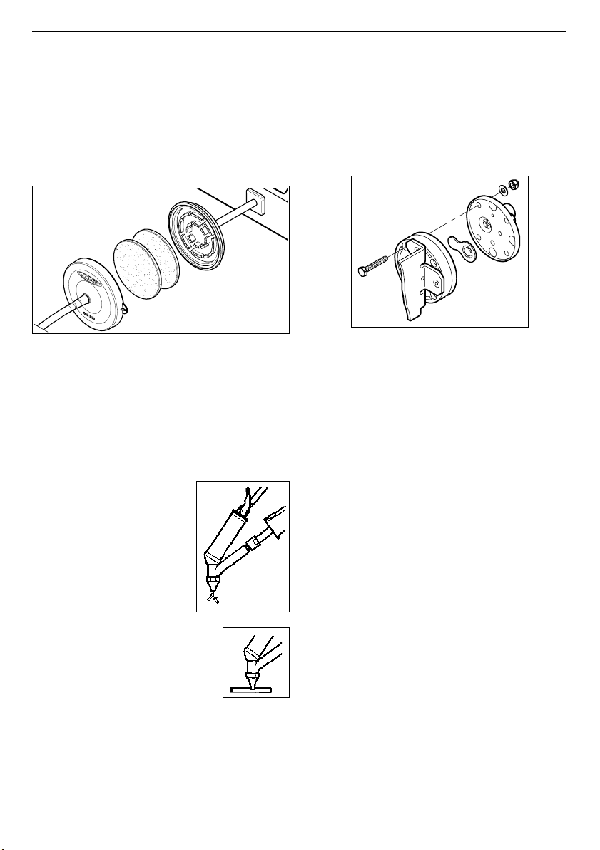
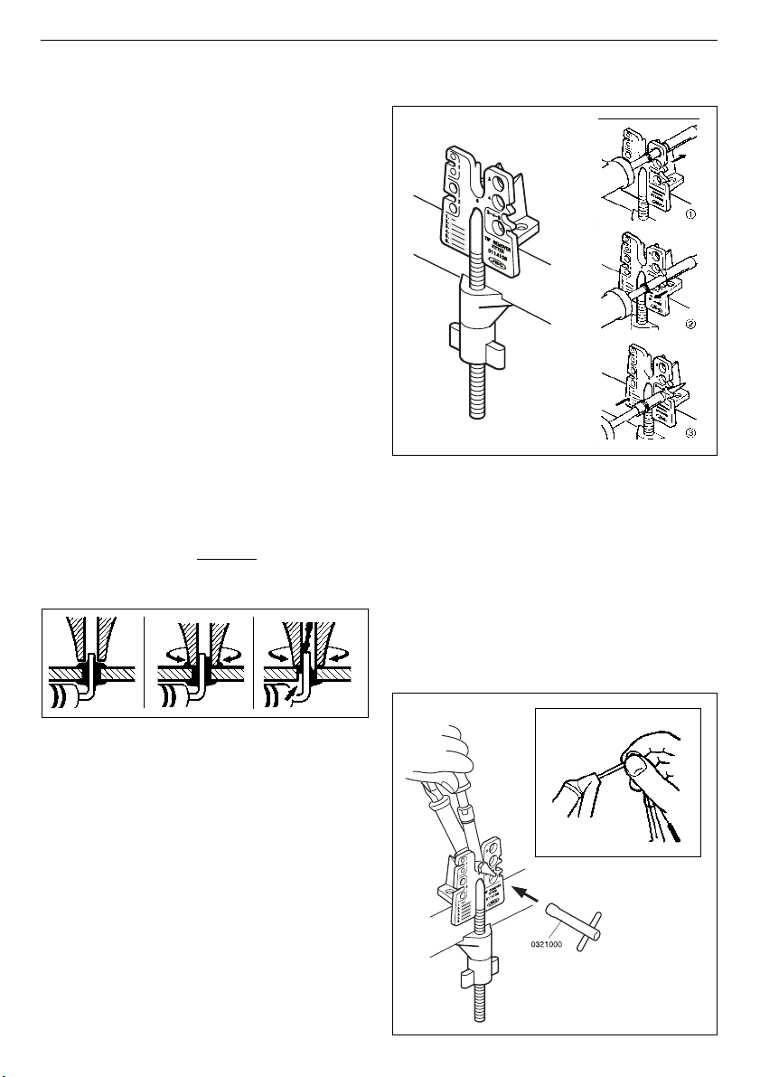
Cambio de punta del desoldador
Esta operación debe realizarse en caliente a una
temperatura mínima de 250°C, para que los
residuos de estaño que hayan quedado en el
interior estén fundidos.
- Apoye el cuerpo del desoldador en el
extractor de puntas y desenrosque la punta
a sustituir, con la ayuda de la llave que se
suministra (Fig. a).
- Pase la baqueta más gruesa por el interior del
conducto del cuerpo desoldador (Fig. b).
➂Introduzca la nueva punta y asegúrese de
que ha penetrado a fondo.
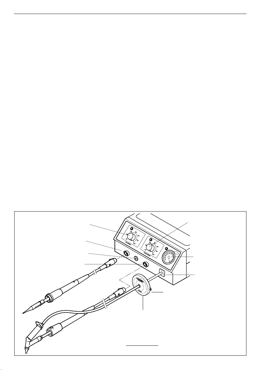
RECOMENDACIONES DE USO
Para soldar y desoldar
- Los componentes y el circuito deben estar
limpios y desengrasados.
- Con preferencia seleccione una temperatura
inferior a 375°C. El exceso de temperatura
puede provocar el desprendimiento de las
pistas del circuito impreso.
- La punta debe estar bien estañada para
conducir bien el calor. Si permanece mucho
tiempo en reposo, estáñela de nuevo.
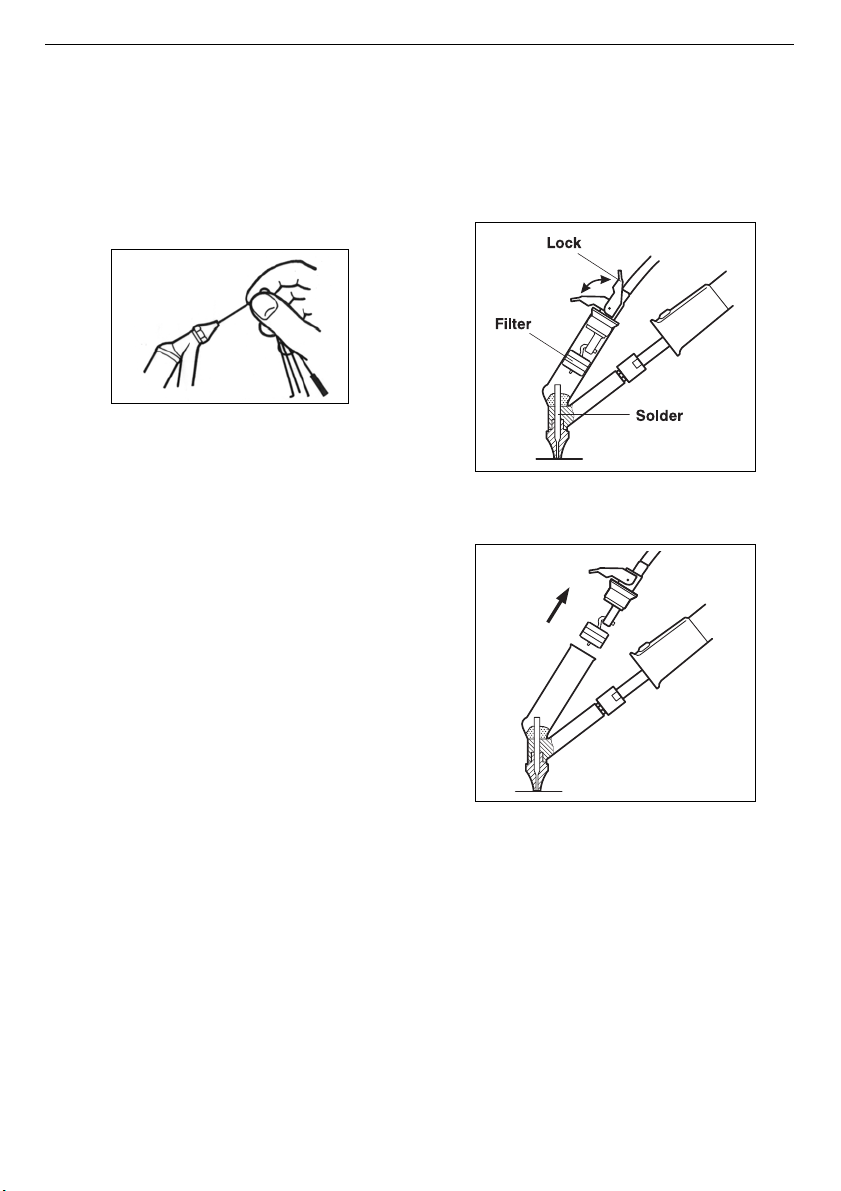
Proceso para desoldar
Utilice un modelo de punta de mayor diámetro
interior que el pin a desoldar, con el fin de
conseguir el máximo de aspiración y de
transmisión térmica.
1Apoye la punta del desoldador, de forma
que el terminal del componente penetre dentro
del orificio de la punta.
2Cuando la soldadura se licúe, imprima a la
punta del desoldador un movimiento de
rotación que permita desprender de los
laterales el terminal del componente.
3Accione entonces, no antes, el pulsador de
la bomba de vacío el tiempo necesario para
succionar la soldadura.
Cambio de punta del soldador
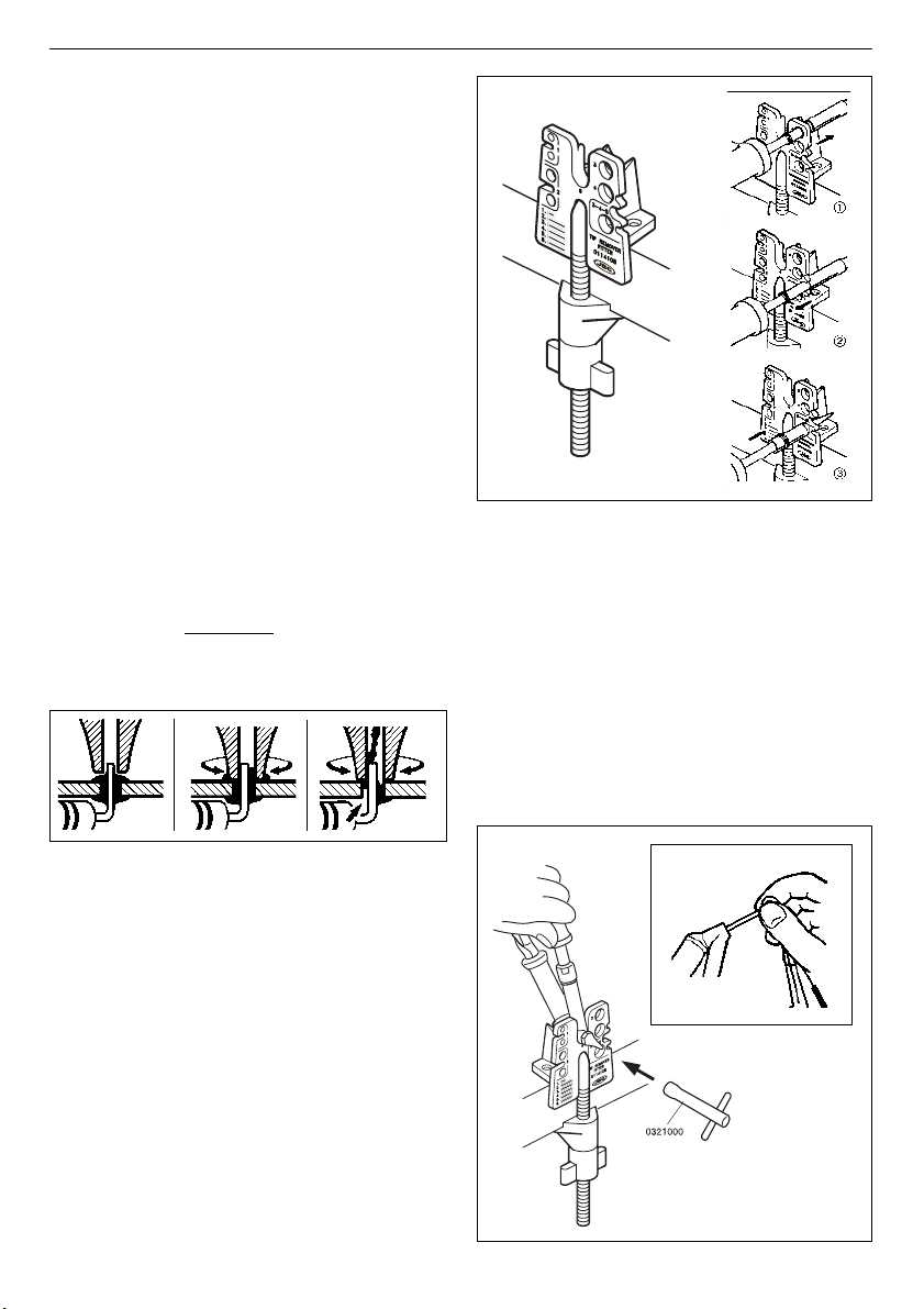
Utilice el extractor de puntas Ref. 0114108.
➀Retire la anilla para liberar la punta.
➁Extraiga la punta tirando del soldador, en
sentido longitudinal y sin forzar la resistencia.
Después de cada pulsación del botón del
desoldador hay un breve retardo hasta el paro de
la bomba de aspiración, con la finalidad de
asegurar que se vacía completamente el circuito
de aspiración.
Si algún terminal ha quedado con restos de
soldadura, después de intentar desoldarlo,
suéldelo nuevamente aportando estaño y repita
la operación de desoldar.