ENGLISH
3
1 Introduction
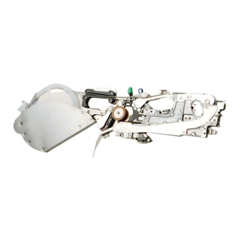
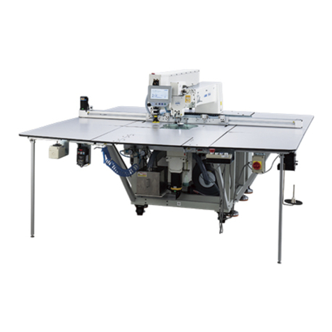
This manual mainly explains how to attach or detach a tape reel for EF08HD.
For detailed functions, refer to"Instruction Manual" in "Instruction Manual CD version" attached to a mounter and also "EF08HD
Instruction Manual. "
2 Name of each part
25
23 24
28
27
1 432 5
6
7
8
9
10
11
12 13 14 15 16
17 18 19 20 21 22 26
3 Operation panel section
Name of operation LED
display Button operation Explanation of operation
Feed pitch setting 02 / 04
Press ■switch button twice
Press ▲switch button or ▼switch button to
change a feed pitch
Press ■switch button twice
To switch a feed pitch to 2 mm and 4 mm
Initialization 0H Press ■switch and ▼switch at the same time To put it into states that can be produced
Initialization completion state
cancellation Press and hold ■switch button long To cancel initialization state
Normal rotation pitch feed Press and hold ▲switch button long To feed a tape by a pitch
Reverse rotation pitch feed Press and hold ▼switch button long To reverselyfeed a tape by a pitch
Operation stop Press ■switch button short To stop feed operation and initialization operation
Error reset E Press ■switch button short To cancel error display
Operation lane change Press switch button alone To be able to change operation effective lane
(between Land R)
Buttonoperation Pressa switch button short:: for less than one second
Pressaswitchbutton long: for one second or more
Pressabuttontwice:thesame switch button for less than one second and two times in sequence
Pressabuttonatthe same time: two switch buttons at the same time
4 Specification
Product code EF08HD/EF08HD (IS) Feed pitch 2 and 4 mm
Color of lever Blue Number of occupied positions 1
Outside dimensions Entire length: 911 mm, height: 455 mm,
and width: 17 mm(Areel support is attached.) Mass 3.0kg
Power supply Supplied from a mounter Component transportingmethod Motor-driven
Power-supply voltage DC 24V Allowable current 2.1A
Tape size Available two 8 mm tapes
(0603 or bigger component) Tape types Paper and embossed tapes
Emboss tape conditions Applicable component emboss width : 4.3 mm or less Applicable component emboss depth : 3.5 mm or less
Operation environmental
conditions during operation Temperature: 10℃to 35℃, humidity: 30 to 80% RH (No condensation), altitude: 1,000 m or less
Accuracy guarantee
temperature Temperature: 20℃to 25℃
Noise 57.7dB(A)
Excessive voltage class Class 1 (IEC60664-1): Excessive voltage is supplied from the circuit whose voltage is limited to a low level (such as a secondary low
voltage circuit)
Environmental pollution level Level 3: Environment whose pollutionis worse than that of the normal environment (such as a manufacturing plant)
* Use componentswhose size and tape specifications conform to JIS C0806-3:1999 and IEC 60286-3:2007.
No. Description No. Description No. Description
1 Upper cover (L/R) 11 Lock release lever 21 Tape loading slot (L lane)
2 Sprocket wheel (L/R) 12 Front liner block assy 22 Reel support guide
3 Cover tape U guide 13 RFID tag (for the IS specification only) 23 Reel support Lassy
4 Tensioner arm (L/R) 14 Slide rail 24 Reel support arm
5 Idler arm (L/R) 15 X guide pin R 25 Tail guide
6 Grip chamber frame 16 Lock section (Bank clamp section) 26 Reel hook
7 Operationpanel 17 Connector 27 PP cap
8 Storage space for PP cap and Tape support 18 Bottom guide block 28 Tape support
9 Chamber lid 19 Rating plate
10 Tape loading slot (R lane) 20 Revision label

