JUKI ACF-164-1903 Quick start guide

R
ENGINEER’S MANUAL
29347606
No.00
Button Attaching Indexer
ACF-164-1903

PREFACE
This Engineer’s Manual is written for the technical personnel who are responsible for the service and maintenance
of the sewing machine. This manual describes “Adjustment Procedure”, “Results of Improper Adjustment”, and
other functions which are not covered by the Instruction Manual intended for the maintenance personnel and
sewing operators at a sewing factory.
All personnel engaged in repair of ACF-164-1903 are required to carefully read Section 2 “Standard Adjustment”
which contains important information on the maintenance of ACF-164-1903.
The “Standard Adjustment” consists of two parts ; the former part presents illustration and simplified explanation
for the convenience of reconfirmation of the required adjustment values in carrying out actual adjustment after
reading this manual once; and the latter part provides “Results of Improper Adjustment” in which sewing and/or
mechanical failures, and the correcting procedures are explained for those persons who perform such adjustment
for the first time.
It is advisable to use “ACF-164-1903 Parts Book” together with this Engineer’s Manual.

CONTENTS
1. SPECIFICATIONS .......................................................................................................... 1
(1) Main unit................................................................................................................................................ 1
(2) Button sewing machine ......................................................................................................................... 1
(3) Button feeder......................................................................................................................................... 2
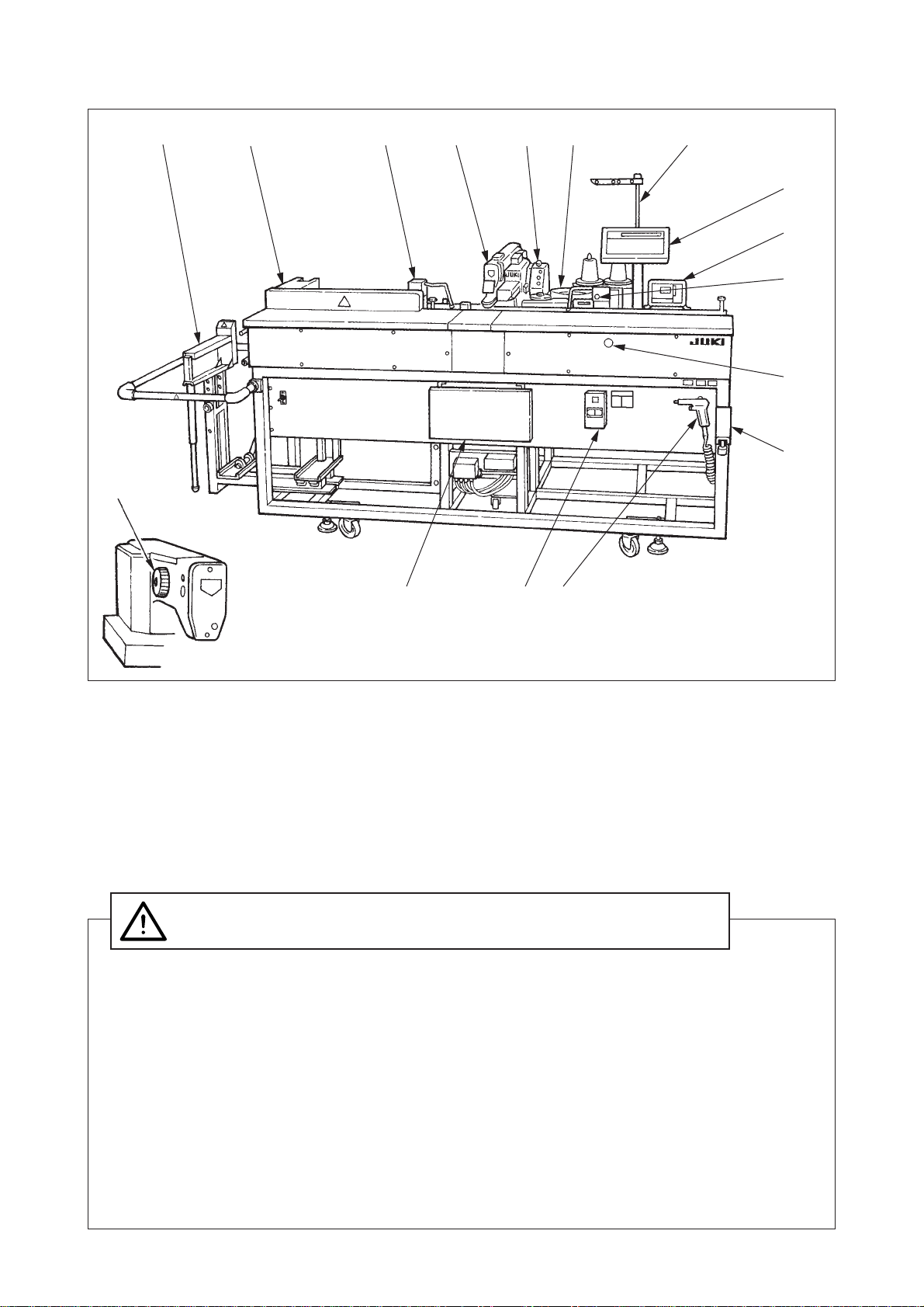
2. CONFIGURATION OF THE MAIN PARTS .................................................................... 3
3. NAME OF EACH PART AND PREPARATION FOR TRIAL RUN................................. 4
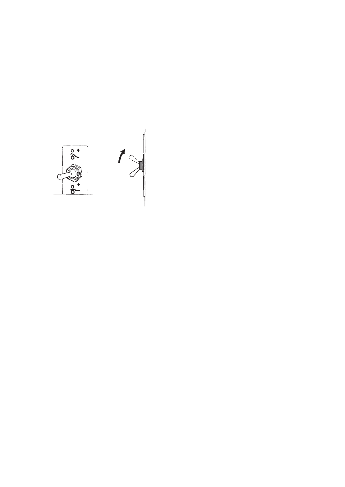
(1) Operating switches................................................................................................................................ 4
(2) Adjusting the seam allowance............................................................................................................... 6
(3) Adjusting the position of the work clamp............................................................................................... 8
(4) Adjusting the stacker............................................................................................................................. 9
(5) Adjusting the knee switch...................................................................................................................... 9
4. OPERATION OF LK ..................................................................................................... 10
(1) NAMES ON THE operation BOX OF LK............................................................................................. 10
(2) HOW TO OPERATE THE operation BOX OF LK ............................................................................... 10
1) Setting the item data.................................................................................................................... 10
2) Changing to the other sewing pattern........................................................................................... 13
3) Performing sewing using the function keys (
P1
,
P2
and
P3
keys) ........................................ 13
4) Adjusting the position of the button clamps ..................................................................................14
5) Checking the contour of a sewing pattern .................................................................................... 15
(3) Winding the bobbin thread .................................................................................................................. 16
1) To wind a bobbin while the sewing machine is performing sewing .............................................. 16
2) To wind a bobbin independently................................................................................................... 16
5. ADJUSTMENT OF COMPONENTS OF LK ................................................................. 17
(1) Adjusting the feed plate....................................................................................................................... 17
(2) Adjusting the button clamp jaw lever................................................................................................... 17
(3) Adjusting the lifting amount of the button clamp ................................................................................. 18
(4) Adjustment of the pressure of the button clamp unit........................................................................... 18
(5) Adjustment of the wiper....................................................................................................................... 19
(6) Adjustment of the wiper spring............................................................................................................ 19
(7) Adjusting the rising amount of the thread tension disk........................................................................ 20
(8) The moving knife and counter knife .................................................................................................... 20
(9) Cleaning the filter ................................................................................................................................ 21
(10) Adjusting the height of the needle bar............................................................................................... 21
(11) Adjusting thre needle-to-hook relation .............................................................................................. 21
(12) How to use the memory switch ......................................................................................................... 22
1) Starting the memory switch .......................................................................................................... 22
2) Example of the memory switch setting .........................................................................................23
3) Setting the counter operation ....................................................................................................... 24
4) Table of functions of the memory switch ......................................................................................25
6. OPERATION OF ACF .................................................................................................. 26
(1) Explanation of the operation panel of ACF ......................................................................................... 26
(2) Preparation before operation .............................................................................................................. 27
(3) Inputting and confirming data.............................................................................................................. 27
1) Memory number selection ............................................................................................................ 27
2) Input of the sewing data ............................................................................................................... 28
3) Checking the sewing data ............................................................................................................ 31
4) Counter settings ........................................................................................................................... 33
(4) Operation ............................................................................................................................................ 34
1) Automatic operation...................................................................................................................... 34
2) Manual operation.......................................................................................................................... 35
3) Independent operation.................................................................................................................. 35
4) Emergency stop............................................................................................................................ 36
5) Error message and the reset procedure....................................................................................... 36

7. SWITCHES INSIDE THE PANEL BOX AND THE CONTROL BOX ........................... 42
(1) Inside the panel box ............................................................................................................................ 42
(2) Inside the control box .......................................................................................................................... 42
8. ADJUSTMENT OF UNIT .............................................................................................. 46
(1) Carriage unit........................................................................................................................................ 46
(2) Button feeder components .................................................................................................................. 56
(3) Detecting mechanism and its adjustment ........................................................................................... 63
(4) Replacing the components and positioning them ...............................................................................66
9. MAINTENANCE INSPECTION..................................................................................... 69
(1) Maintenance and inspection of the sewing machine components ...................................................... 69
(2) Maintenance and inspection of electrical components........................................................................ 69
(3) Diagnostic feature ............................................................................................................................... 69
10. PERFORMANCE FLOW CHART............................................................................... 75
11. SEQUEMCE CHART .................................................................................................. 83
12. AIR PIPING................................................................................................................. 85
13. WIRING COMPONENTS ............................................................................................ 87
14. CONFIGURATION (ELECTRICAL UNIT) .................................................................. 89
(1) Components of control box and its function ........................................................................................ 89
(2) Connector and its functions of the control box .................................................................................... 90
(3) Power voltage ..................................................................................................................................... 91
(4) Measuring the DC power voltage........................................................................................................ 92
(5) Changing the thermal values inside the switch box ............................................................................ 93
(6) Replacing fuses................................................................................................................................... 93
(7) Replacing the P-ROMs for data .......................................................................................................... 94
(8) CPU circuit board ................................................................................................................................ 95
(9) I/O circuit board................................................................................................................................... 96
(10) Power circuit board ........................................................................................................................... 97
(11) Panel circuit board ............................................................................................................................ 98
(12) Functions of the stepping motor driver.............................................................................................. 98
(13) I/F circuit board whole asm. .............................................................................................................. 99
15. BLOCK DIAGRAM ................................................................................................... 100
16. BLOCK DIAGRAM ................................................................................................... 101
17. WIRING DIAGRAM................................................................................................... 102
18. CIRCUIT DIAGRAM ................................................................................................. 105
(1) Transformer (ass’y) ........................................................................................................................... 105
(2) Power circuit board (ass’y) circuit diagram ....................................................................................... 106
(3) Circuit diagram of the stepping motor driver (ass’y).......................................................................... 107
(4) Circuit diagram of the stepping motor (ass’y).................................................................................... 107
(5) Circuit diagram of the indexer switch ................................................................................................ 108
(6) Output circuit board diaram............................................................................................................... 109
19. TROUBLES AND CORRECTIVE MEASURES........................................................ 111
20. TROUBLES AND CORRECTIVE MEASUTRES ..................................................... 112

−1 −
1
2
6
4
5
6
Outer diameter of buttons to be sewn (mm)
Sewing size (mm)
Button clamp jaw lever
Needle hole guide
Feed plate
Length
Width
Thickness
(mm)
Standard
For small buttons
ø10 to ø15
0 to 3.5
0 to 3.5
2.2 Engraved
mark
MAZ165070B0 H
MAZ167140A0
MAZ15601000
MAZ15502000
Optional
For medium-size buttons
ø12 to ø18
0 to 4.5
0 to 4.5
2.7
MAZ166070B0 J
MAZ168140A0
MAZ15601000
MAZ15602000
Part
No.
Right
Left
Engraved
mark
1. SPECIFICATIONS
(1) Main unit
1Feed interval : 25 to 650 mm (1 to 25.6”)
2Overall feed amount : 650 mm (25.6”)
(When the machine is set to the long-sized material sewing
mode : 1,200 mm)
3Number of buttons
which can be sewn : 1 to 20 pcs. (the machine is
set to the independent sewing
mode when sewing only one
button on the material.)
4Distance from the top end of the
garment body to the 1st button : 40 to 140 mm (1.6 to 5.5")
(20 mm or more : when the
special order part is used.)
5Distance from the side end of the
garment body to the button : 12 to 25 mm (0.5 to 1")
6Applicable garment sizes
that can be sewn (standard) : Width 220 to 420 mm (8.7 to 16.5")
Length 400 to 880 mm (15.7 to 34.6")
7Number of patterns
that can be stored in memory : 20
8Power supply : 200V (3-phase) (Rated voltage ±10%)
9Power source frequency : 50/60 Hz
!0 Power consumption : 600 VA (Rated voltage ±10%)
!1 Operating air pressure : 0.5 MPa
!2 Air consumption : 20 Nl/min. or less
!3 Machine dimensions : Width 1,860 mm
Depth 970 mm
Height 1,250 mm
!4 Weight : 220 kg
(2) Button sewing machine
1Machine head : LK-1903 (exclusive machine head)
2Sewing speed : Normal 2,300 rpm
Max. 2,700 rpm [only when using the Z165 (for small button)
and cotton thread]
3Needle : DP x 17 #14
4Buttons : Kind : Flat buttons (2-holed, 4-holed)
5Lifting amount of
button clamp jaw lever : 11 mm
6Number of standard patterns : 33

−2 −
(3) Button feeder
1Discrimination of buttons to be fed : By vibration system using the piezoelectric feeder
2Button setting method : Buttons are loaded from the rear section of device
3Individual button feed : By index method
4Detection of a failure : Provided with three detectors ™The first detector detects a
button at the section where
the button is correctly
positioned.
™The second detector checks
whether the button is correctly
inserted in the carrier pin.
™The third detector detects a
button at the button clamp jaw
lever.
5Driving source for the feeder : DC motor (24 Vdc)
6Function of sewing buttons
without cross-over stitch : Provided
7Automatic button
discharging function : Provided
8Independent operation of the
sewing machine : Possible
9Time required to feed a button : 0.5 sec./pc.
Noise: Workplace-related noise at sewing speed
n = 2,300 min–1 : LPA ≦84 dB(A)
Noise measurement according to DIN 45635-48-B-1.

−3 −
2. CONFIGURATION OF THE MAIN PARTS
1Sewing machine head
2Button feeder
3Work clamp (carriage unit)
4Stacker
5Operation panel of ACF
6Power switch
7Knee switch
8Emergency stop switch
9Hand switch
!0 Thread stand
!1 Conveyor
!2 Cloth plate
!3 Operation panel of the feeder
!4 Air gun
!5 Operation box of LK
!6 Hand pulley
1. Before you put the machine into operation for the first time after the set-up, clean it
thoroughly. Remove all dust gathering during transportation and oil it well.
2. Confirm that the voltage has been correctly set.
Confirm that the power plug has been properly connected to the power supply.
3. Never use the machine in the state where the voltage type is different from the designated one.
4. The sewing machine has been completely adjusted at the time of delivery. For caution’s sake,
however, turn ON the power switch after releasing the stop-motion and turning the handwheel
by hand when operating the machine for the first time.
5. Operate the machine with the air pressure set to 0.5 MPa (5 kgf/cm2).
CAUTION :
To avoid malfunction and damage of the machine, confirm the following :
12
3
4
5
6
7
8
9
!0!1
!2
!3
!4
!5
!6

−4 −
A
3. NAME OF EACH PART AND PREPARATION FOR TRIAL RUN
(1) Operating switches
1Power switch
Use this switch to turn ON/OFF the power to the unit.
(If installing the optionally available MC-6,use independent power for the MC-16 that is located on
section A on the right-hand side of the main unit.)
2Emergency stop switch
Use this switch to stop the machine from running.
3Knee switch
This switch is used as the start switch.
4Hand switch
This switch is used as the work clamp release switch.
5Feeder switch
6Button feeder switch
Used to supply buttons to the button clamp jaw lever.
7Set-up switch
This switch is used for operating the spinner oscillating arm under the step-operation mode. The spinner
oscillating arm performs step operation as long as the switch is held pressed.
8Button discharging switch
This switch is used to discharge buttons in the index unit.
d
1
2
3
4
5
6
7
8
9
!0
!1
!2

−5 −
9Feeder breaker
This is the breaker for the spinner oscillating arm motor and index unit motor. This breaker can be reset
by pressing.
!0 Men’s / Ladies mode selective switch
Used to change modes when sewing men’s or ladies’ wear.
!1 Body of the garment / finished garment mode selective switch
Used to change modes when sewing garments using the finished workpiece table (Optional :
G55101640A0).
!2 Stacker release switch
This switch is used when sewing garments using the second presser (Optional : G55141640A0).
This switch is used for taking out the materials from
the stacker after the predetermined number of pieces
of finished material has been stacked. Lift lever in the
direction of arrow A, and the second presser will move
away from the stacking board to allow the operator to
take out the materials from the stacker.
(Caution) Do not take out the workpieces while the
stacker is in operation. Doing so is very
dangerous.
Stacker release switch
A

−6 −
(2) Adjusting the seam allowance
1In the case of sewing garment bodies of men’s wear (set Men's/Ladies' mode selective switch !0
mounted on the right-hand side of the operation panel to its lower side.) (See p.4.)
1) Adjust the seam allowance from the side end of
the garment to the button (distance A in the figure),
and from the top end of the garment to the 1st button
(distance B in the figure.)
(Caution) Be sure to make adjustment of the seam
allowance after you have turned OFF the
power switch.
2) The number of buttons and the intervals between
the buttons can be adjusted using the panel
switches. (Refer to “Inputting the sewing data” on
page 28.)
™Adjusting distance A
Loosen screws 1in setting plates,right 2and left 3. Shift the respective setting plates to the desired
values and tighten the screws.
™Adjusting distance B
Loosen thumbscrew 1, and shift gauge 2to the right or left until desired scale value 3is reached.
Then tighten the thumbscrew.
As viewed from above the unit
A
B
As viewed from above the unit
1
23
1
2
3
111

−7 −
2In the case of sewing garment bodies of ladies’ wear (set Men's/Ladies' mode selective switch !0
mounted on the right-hand side of the operation panel to its upper side.) (See p.4.)
1) Adjust the seam allowance from the side end of
the garment to the button (distance A in the figure),
and from the top end of the garment to the 1st button
(distance B in the figure).
The number of buttons and the intervals between
the buttons can be adjusted using the panel
switches. (Refer to “Inputting the sewing data” on
page 28.)
(Caution) Be sure to make adjustment of the seam
allowance after you have turned OFF the
power switch.
2) Adjust dimension A for ladies’ wear should be
adjusted following the same procedure as that for
men’s wear.
™Adjusting distance B Insert gauge 1for ladies’ wear supplied with the
machine into setting plate,right 2. Then shift the setting
plate to the right or left according to scale value 3
desired.
™Dimension B can also be adjusted in the following procedure.
(Caution) In this case, perform the adjustment after changing over the operation mode from the
ladies' wear sewing mode to the men's wear sewing mode.
Move gauge 1for ladies’ wear supplied with the machine toward the right-hand side of setting plate, right
2. Then sewing is carried out in the order from the button that is closest to the bottom edge of the garment
body toward the first button at the top.
A
B
B
12
3
12

−8 −
(3) Adjusting the position of the work clamp
The position of the work clamp of this unit can be adjusted as desired according to the size of garment to
be sewn.
1For garment bodies of men’s wear
Loosen knob 4and shift left-hand side work clamp 2to its leftmost position. Then tighten the knob so that
the left-hand side work clamp is fixed at that position. Then loosen knob 1and adjust the position of right-
hand side work clamp 5according to the length of the workpiece to be sewn.
(Caution) When making adjustment,be sure that work clamp (right) 6is positioned in the right side
of the last button and the distance between them is 40 mm or more. If work clamp (right)
6is not positioned as stated above, the Error (E52) may occur when the machine runs
under the automatic operation mode.
2For garment bodies of ladies’ wear
Loosen knob 1and shift left-hand side work clamp 5to its rightmost position. Then tighten the knob so
that the work clamp is fixed at that position. Then adjust the position of left-hand side work clamp 2
according to the length of the workpiece to be sewn.
(Caution) When making adjustment, be sure that work clamp (left) 3is positioned in the left side
of the last button and the distance between them is 40 mm or more. If work clamp (left) 3
is not positioned as stated above, the Error (E52) may occur when the machine runs in
the automatic operation mode.
This device is equipped with a conveyer on its left-hand side. This may prevent you from
setting garment bodies of ladies' wear in place on the machinre with ease. In this case,
you can attach buttons of the garment from its bottom by using the jump function (see
p.31.) and the men's wear sewing mode in combination.
1
2
1
45
6
5

−9 −
(4) Adjusting the stacker
(Caution) The stacker provided for this device automatically computes the timing to stack the
garment regardless of its size and atacks the garments on the stacking board as long as
its dimensions are about 180 mm wide or more and 1,000 mm long or shorter. (The stacker
does not actuate under the long-material mode or the finished garment mode).
Approximately 140 garment bodies (material: T/C broad cloth) with a folded top center
plait can be stacked.
1) If the garment bodies are stacked on stacking board 3with its side Ashortened,loosen fixing knob 6
and raise stacking board 3. The stacker can also be adjusted by tightening speed controller 9(turning
speed controller clockwise) of work clamp cylinder 7.
At this time,loosen fixing knob 4, and adjust so that work clamp 1contacts with the center of stacking
board 3. Then confirm that swing bar 2does not come in contact with stacking board 3. (If the bar
comes in contact with the board,loosen fixing knob 5, and adjust the height of the stacking board
properly.)
2) If the garment bodies are stacked on stacking board 3with its side Bshortened, lower stacking board
3.
3) The machine is designed to detect the quantity of garments stacked on the stacker using sensor 8
mounted on work clamp cylinder 7. You can make the alarm occur when the quantity of the stacked
garment reaches the desired volume predetermined only adjusting the position of sensor 8appropriately.
(Even when the alarm occurs,the machine will not stop running.)
(5) Adjusting the knee switch 1) Loosen screw 2in the switch fixing plate 1, and
adjust the stroke of the knee switch.
2) Now,confirm that presser plate 4stops when
stopper 3is reached without fail.
As viewed from above the unit
1
2
3
4
5
6
7
8
9
A
B
1
2
34
3

−10 −
4. OPERATION OF LK
(1) NAMES ON THE operation BOX OF LK
• Sewing LED • Item selection LED
• Selection key: Every time this key is pressed, the selection
will be made as follows.
• Function key
• +/Forward key
• −/Back key
• Ready key
• Reset key
• Data display
Pattern No. →X Scale →Y Scale →Speed →Counter →Bobbin winder
↑
(2) HOW TO OPERATE THE operation BOX OF LK
1) Setting the item data
Set each item following the procedure described below.
1Turn ON the power switch.
Pattern No. of the item selection lights up, and the pattern No. is indicated on the data display.
(Pattern No. 1 has been set at the time of delivery.)
2Setting of the pattern No. 1) Press the SELECT keytoindicate the item“PATTERN
No.”.
2) Press the
FORWARD
or
BACK
key to indicate “ ”on the
screen.
(Pattern No. is set to 14.)
(Caution) For the pattern No. refer to the table of
the standard sewing patterns (p.12).
Setting of the
pattern No. Setting of the X scale Setting of the Y scale Setting of the max.
sewing speed limitation
SELECT
FORWARD
BACK
PATTERN No.
X SCALE
Y SCALE
SPEED
COUNTER
WINDER

−11 −
3Setting of the X scale 1) Press the SELECT key to indicate the item “X
SCALE”.
2) Press the
FORWARD
or
BACK
key to set the scale in the
range of 20% to 200%.
4Setting of the Y scale 1) Press the SELECT key to indicate the item “Y
SCALE”.
2) Press the
FORWARD
or
BACK
key to set the scale in the
range of 20% to 200%.
5Setting of the max. speed limitation 1) Press the SELECT key to indicate the item “SPEED”.
2) Press the
FORWARD
or
BACK
key to indicate “ ” on
the screen. (Setting of 400 rpm)
6Finish of setting 1) Press the READY key.
2) After the work clamp feet have moved and gone
up, the sewing LED lights up, and the sewing is
ready.
*If the
SELECT
key is pressed, you can make sure of
the set values of the respective items again.
SELECT
FORWARD
BACK
PATTERN No.
X SCALE
Y SCALE
SPEED
COUNTER
WINDER
SELECT
FORWARD
BACK
PATTERN No.
X SCALE
Y SCALE
SPEED
COUNTER
WINDER
SELECT
FORWARD
BACK
PATTERN No.
X SCALE
Y SCALE
SPEED
COUNTER
WINDER
READY
SEWING
(Caution) Use the sewing machine after checking the pattern No. If the Ready switch is pressed
while the pattern No. "0" is being displayed (state at the time of delivery), Error "E-1" is
displayed. At this time, perform re-setting of the pattern No.

−12 −
2.4 2.6 2.8 3.0 3.2 3.4 3.6 4.0 4.3 4.5 4.7 5.2 5.6 6.0 6.2 6.4
% 71 76 82 88 94 100 106 118 126 132 138 153 165 176 182 188
X, Y
(mm)
1 (34) 6-6
2 (35) 8-8
3 10-10
4 12-12
5 (36) 6-6
6 (37) 8-8
7 10-10
8 12-12
9 (38) 6-6
10 (39) 8-8
11 10-10
12 (40) 6-6
13 (41) 8-8
14 10-10
15 (42) 6-6
16 (43) 8-8
17 10-10
18 (44) 6
19 (45) 8
20 10 3.4 0
21 12
22 16
23 (46) 6
24 10 0 3.4
25 12
26 (47) 6-6
27 10-10
28 (48) 6-6
29 10-10
30 (49) 5-5-5
31 8-8-8
32 (50) 5-5-5
33 8-8-8
3.4 3.4
3.4 3.4
2.9 2.5
Standard
sewing
size Y
(mm)
Pattern
No. Stitch
shape
Number
of
threads
(thread)
Standard
sewing
size X
(mm)
TABLE OF THE STANDARD SEWING PATTERNS
Standard
sewing
size Y
(mm)
Pattern
No. Stitch
shape
Number
of
threads
(thread)
Standard
sewing
size X
(mm)
*The standard sewing sizes of X and Y are when the enlargement/reduction rate is 100%.
*Use (34) to (50) when the button hole is small (ø1.5 mm or less).
Table of X/Y scales in terms of the sewing width

−13 −
1Registration to the function key
Setting example : Register the following setting to the P1.
Pattern No. 3, X Scale rate : 50%, Y Scale rate : 80%, Max. sewing speed limitation : 2,000 rpm
1) Pressing the SELECT key, turn ON the power switch.
2) Press the
P1
key.
3) Press the
SELECT
key to indicate the PATTERN No.
Set the pattern No. to Pattern No. “ ” using the
FORWARD
or
BACK
key.
4) Press the
SELECT
key, ans set X scale rate to 50%, Y Scale
rate to 80% and Max. sewing speed limitation to 2,000 rpm
using the
FORWARD
or
BACK
key.
5) Press the
READY
key to finalize the registration.
*If you desire to register in P2 to P7, select P2 to P7 in combination of
P1
to
P3
keys at the step 2),
and perform the steps 3) to 5).
6) When the registration has been completed, turn OFF the power switch, and again turn ON the powr
switch. Then the sewing machine can be used as usual.
e
e
e
2) Changing to the other sewing pattern
1Press the READY key. (The sewing LED will go off.)
2Pressthe
SELECT
keyto indicate theitem“PATTERN
No.”.
3Set the items 2through 6of 1) setting the item
data, and move to the step of “5) Checking the
contour of a sewing pattern”.
SELECT
FORWARD
BACK
PATTERN No.
X SCALE
Y SCALE
SPEED
COUNTER
WINDER
READY
3) Performing sewing using the function keys (
P1
,
P2
and
P3
keys)
If the patterns (No. 1 to 99) which have been already registered are registered in P1 to P7, the pattern calling
can be made by one-touch without performing the selection by the pattern No. scrolling.
*When selecting P4, P5, P6 or P7, the selection can be made by the combination of
P1
to
P3
keys.
P1 : Press the
P1
key. P4 : Simultaneously press the
P1
and
P2
keys.
P2 : Press the
P2
key. P5 : Simultaneously press the
P1
and
P3
keys.
P3 : Press the
P3
key. P6 : Simultaneously press the
P2
and
P3
keys.
P7 : Simultaneously press the
P1
,
P2
and
P3
keys.
e

−14 −
P1
P3
Needle entry position
Holes in the button
Button
4) Adjusting the position of the button clamps 1) Set the mode to “Independent operation” mode
(P.35) with the operation panel of ACF.
2) Press the button feeding switch (P.4) on the BR
control box, and place a button in button clamps 1.
3) When the knee switch (P.4) is turned ON, button
clamps 1come down.
4) Holding the knee switch ON, turn the hand pulley until
the digital display on the LK control box becomes E3.
5) Release the knee from the knee switch.
6) Further turn the hand pulley to lower the needle
and confirm that the center of the needle is in the
center of the button.
(Caution) If the needle is returned to the up-stop
position when turning the hand pulley,
E3 of the digital display on the LK
control box will disappear, and the
button clamps 1will go up.
7) When the center of the needle is not in the center of the button, loosen setscrews 2in the button clamp
unit and adjust so that the center of the needle is in the center of the button.
8) After the adjustment, turn the hand pulley to return the needle to its up-stop position. Then E3 of the
digital display goes out and the button clamps 1go up.
9) Press again the button feeding button on the BR control box, place a button again and perform the step of
checking the contour of a sewing pattern (P.15). Then confirm that the needle surely enters the hole in the
button.
2Sewing operation
Operation example : After performing sewing with the contents of the registered P1, perform sewing with the
contents of P3. 1) Turn ON the power switch.
2) Press the
P1
key.
3) Press the READY key, and when the sewing LED lights
up, the work clamp foot goes up after it has moved.
4) Check the contour of the sewing pattern.
(Refer to the item “Checking the contour of a sewing
pattern”.)
5) If the contour of the sewing pattern is acceptable,
the sewing can be made.
6) After the completion of sewing, press the
P3
key.
Then the work clamp foot will move to the sewing
start point after the origin retrieval. The P keys can
operate the pattern change by one-touch even
when the sewing LED is lighting up.)
7) Perform the above items 4) and 5).
✽The P1 to P7 keys can be indicated on the display
when selecting the pattern by pressing the
FORWARD
or
BACK
key.
→0 to 99 ←→ P1 to P7 ←
P1 to P7 which have not been registered are not
indicated.
READY
SEWING
READY
SEWING
1
2

−15 −
After 5th stitch
3rd stitch
2nd and 4th stitches
1st stitch (jump feed)
Needle does not enter.
Needle entry origin
5) Checking the contour of a sewing pattern 1) Set the mode to “Independent operation” mode with
the operation panel of ACF. (P.35)
2) Press the button feeding switch (P.4) on the BR
control box, and place a button in button clamps 1.
(See P.14.)
3) When the knee switch (P.4) is turned ON, button
clamps 1come down. (See P.14.)
4) Holding the knee switch ON, press the
FORWARD
key on
the LK control box, and the button clamps move by
one stitch
If the
FORWARD
key is pressed even one time, the button
clampsdonot go upeven when the kneeis released
from the knee switch.
In addition, After the
FORWARD
key has been pressed,
the
BACK
key becomes effective as well.
5) Turn the hand pulley to lower the needle and
confirm that the needle enters the hole of the button.
(Caution) When the hand pulley is turned, E3 of
the digital display on the LK control box
is displayed. When the E3 is displayed,
FORWARD
and
BACK
keys are ineffective. To
make
FORWARD
and
BACK
keys effective, turn
the hand pulley, raise the needle up to
its up-stop position and make E3 go out.
6) After confirmation ofthe needle entry position,prees
the RESET
Rkey on the LK control box. The button
clamps return to the origin and go up.
(Caution) At this time, if E3 is displayed, the
RESET
R
key becomes ineffective. To make the
RESET
R
key effective, turn the hand pulley,
raise the needle up to its up-stop
position and make E3 go out.
*Buttons cannot be fed during confirmation of the
needle entry position. When feeding the buttons
again, press the RESET
Rkey to return the button clamps
to the origin.
FORWARD
BACK
Details of the sewing pattern at the sewing start
™1st stitch is a jump stitch and the needle does
not enter.
™2nd, 3rd and 4th stitches are tie stitches.
Needle enters in the same button hole.

−16 −
(3) Winding the bobbin thread
1) To wind a bobbin while the sewing machine is performing sewing
Thread the bobbin winder and wind the bobbin thread
onto the bobbin as illustrated in the figure.
2) To wind a bobbin independently 1) Pull out the thread from the needle.
2) Winding a bobbin is performed at the position of
the origin of the sewing machine. Be sure to remove
the button from the button clamps.
3) Set the operation panel of ACF to “Independent
operation” mode. (P.35)
4) Press READY key on the control box of LK to make the
sewing LED go out.
5) Select “WINDER” with the SELECT key on the control
box of LK.
6) Press again READY key to light the sewing LED. At this
time, a display as shown below is indicated on the
operation panel of ACF.
7) Press the sewing machine start switch on the operation panel of ACF. Then the sewing machine
rotates and bobbin thread winding is started.
8) To stop the operation, press again the sewing machine start switch on the operation panel of ACF or
press any key on the control box of LK.
9) To return to the normal sewing, press again
READY
key on the control box of LK, select the item other than
“WINDER” with
SELECT
key and press again
READY
key to light the sewing LED.
10) At this time, a display as shown below is indicated on the operation panel of ACF. Then press
switch on the operation panel of ACF.
Sewing machine
start switch on
operation panel of
ACF
SELECT
PATTERN No.
X SCALE
Y SCALE
SPEED
COUNTER
WINDER
READY
***** BOBBIN WINDING MODE *****
LK BOBBIN SW OFF
14 ***** LK NOT READY *******
LK CHECK →RESET →START
*Sewing machine start switch does not work for two seconds after stop of bobbin winding operation.
*Buttons cannot be fed during bobbin winding operation.
*When the operating method of operation panel of ACF is “Automatic operation” (P.34) or “Manual
operation” (P.35), the sewing machine start switch does not work even when performing the
aforementioned operations of steps 4), 5) and 6). Perform the operations of steps 9) and 10) once to set
the operating method of the operation panel of ACF to "Independent operation" mode (P.35), and
perform the operations of the aforementioned steps 4), 5) and 6).
Table of contents
Other JUKI Industrial Equipment manuals

JUKI
JUKI KE-1070 Operating manual

JUKI
JUKI PS-900-13090 User manual

JUKI
JUKI AW-3S User manual

JUKI
JUKI M92 Manual

JUKI
JUKI JX-100 User manual

JUKI
JUKI KE-2000 Series User manual

JUKI
JUKI RS-1 User manual

JUKI
JUKI KE-2050 Operating manual

JUKI
JUKI AMS-221F User manual

JUKI
JUKI LK-1900B series Instruction Manual

JUKI
JUKI KE-3010 Operating manual

JUKI
JUKI TL-2020 PE User manual

JUKI
JUKI JaNets JT Simple User manual

JUKI
JUKI PS-800SB-8045 User manual

JUKI
JUKI L-1A User manual

JUKI
JUKI FX-3R Operating manual

JUKI
JUKI 72005824 User manual

JUKI
JUKI KE-2070 User manual

JUKI
JUKI KE-750 User manual

JUKI
JUKI MEB-3200C User manual