manuals.online logo
Brands
  1. Home
  2. •
  3. Brands
  4. •
  5. Kimball Office
  6. •
  7. Indoor Furnishing
  8. •
  9. Kimball Office Dock Folding Base User manual

Kimball Office Dock Folding Base User manual

Dock™1
Proper product installation, in accordance with these instructions, is the responsibility of the installing agent.
If you have any questions concerning these instructions, please call Kimball Office Customer Care.
Part 2700492, Revision -
Assembly Instructions
Fixed & Height Adjustable
Base to Worksurface Assembly
Tools Required
 Drill
 1/8” Drill Bit
 #3 Phillips Head Bit Drive
Hardware Required
1 - Worksurface
2 - Fixed Bases
16 - #12 x 1 Pan Head Wood Screws
Installation
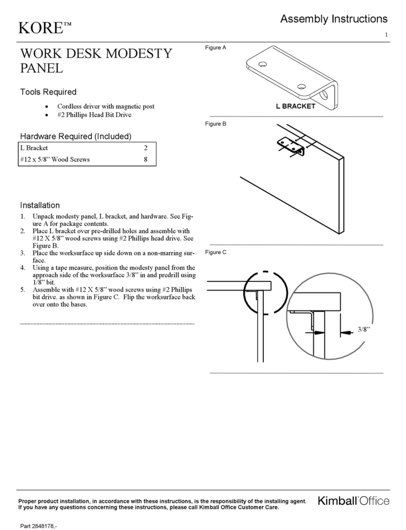
1. Unpack worksurface and place up side down on a non-
marring surface.
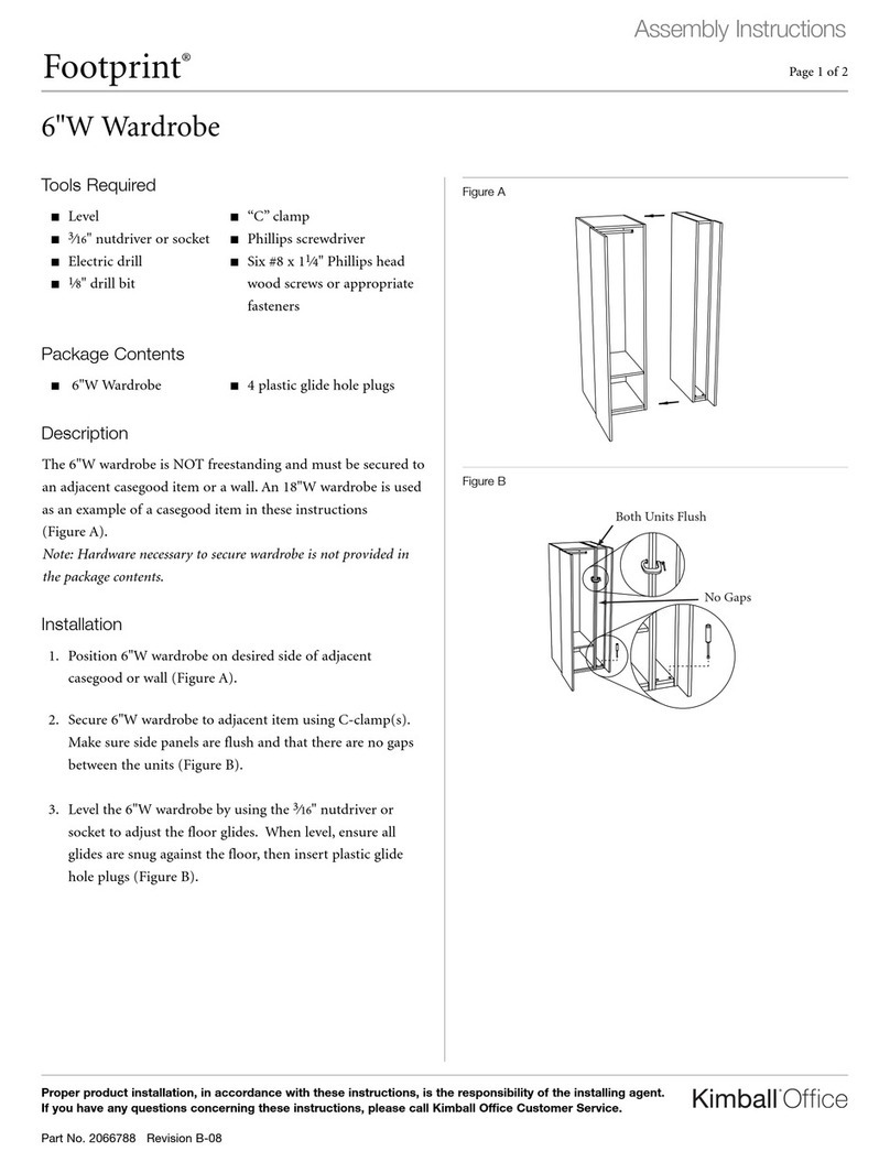
2. Unpack fixed legs from box along with hardware. Note:
They come as a pair. See Figure A.
3. Using a tape measure, position the bases on the top as
shown in Figure B. See reference tables below for base
measurements. The left guide is for a T leg and the right
guide is for a C leg.
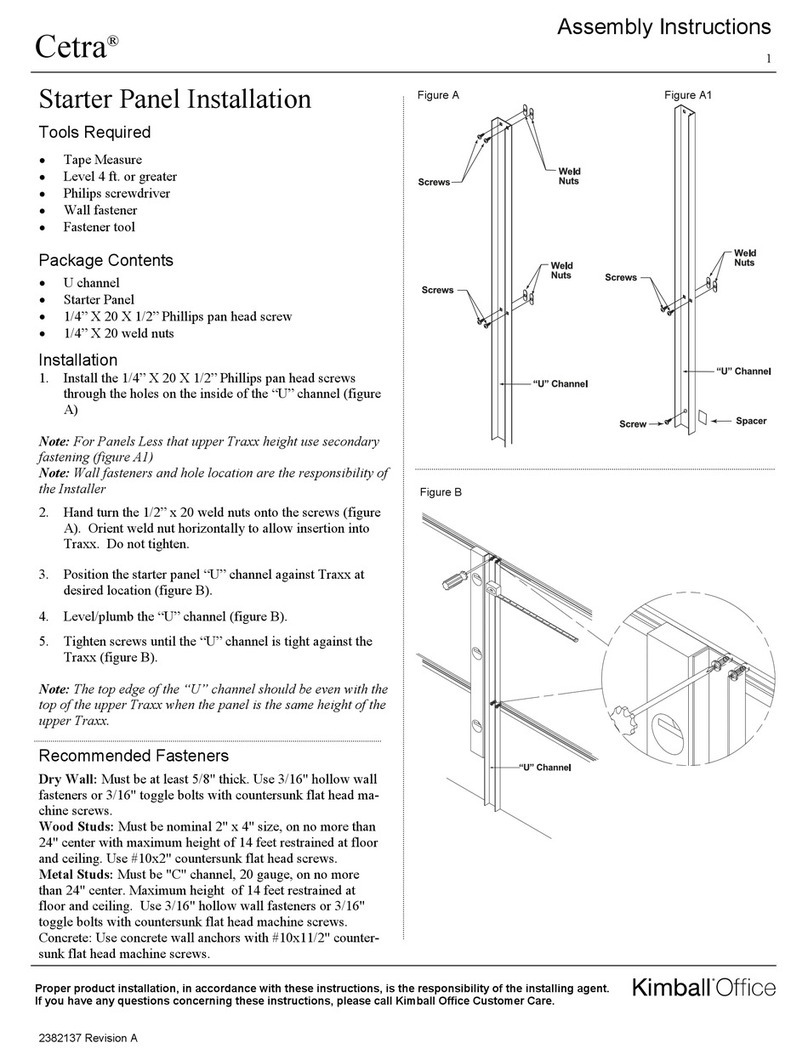
4. Mark and predrill the screw hole locations using a 1/8
inch bit 1/2” into the top. There should be a total of 18
holes drilled.
5. If modesty, support rail, electrical trough, or electrical is
being installed to worksurface, see their respective As-
sembly instructions. Sequence the bases first, followed
by support rails, modesty panels, electrical trough, and
last electrical.
Top Sizes for T leg & Adjustable
bases
AB
18” Depth x 48”-72” Width 1” 5”
18” Depth x 84” Width 7” 5”
18” Depth x 96” Width 13” 5”
24” Depth x 48”-72” Width 1” 8”
24” Depth x 84” Width 7” 8”
24” Depth x 96” Width 13” 8”
30” Depth x 48”-72” Width 1” 11”
30” Depth x 84” Width 7” 11”
30” Depth x 96” Width 13” 11”
Figure A
Figure B
B B
AA
USER SIDE
APPROACH SIDE
USER SIDE
APPROACH SIDE
A A
B B
Top Sizes for C leg bases AB
18” Depth x 48”-72” Width 1” 2”
18” Depth x 84” Width 7” 2”
18” Depth x 96” Width 13” 2”
24” Depth x 48”-72” Width 1” 5”
24” Depth x 84” Width 7” 5”
24” Depth x 96” Width 13” 5”
30” Depth x 48”-72” Width 1” 8”
30” Depth x 84” Width 7” 8”
30” Depth x 96” Width 13” 8”
RIGHT LEG
LEFT LEG
Konfig
T-Base
Konfig
C-Base
Tubular
T-Base
KONFIG T-Base shown
Dock™2
Proper product installation, in accordance with these instructions, is the responsibility of the installing agent.
If you have any questions concerning these instructions, please call Kimball Office Customer Care.
Part 2700492, Revision -
Assembly Instructions
Folding Base to Worksurface
Assembly
 Drill
 1/8” Drill Bit
 #3 Phillips Head Bit Drive
Tools Required
Hardware Required
1 - Worksurface
2– Folding Bases
20 - #12 x 1 Pan Head Wood Screws
Installation
1. Unpack worksurface and place up side down on a non-
marring surface.
2. Unpack folding legs from box along with hardware. Note:
They come as a pair.
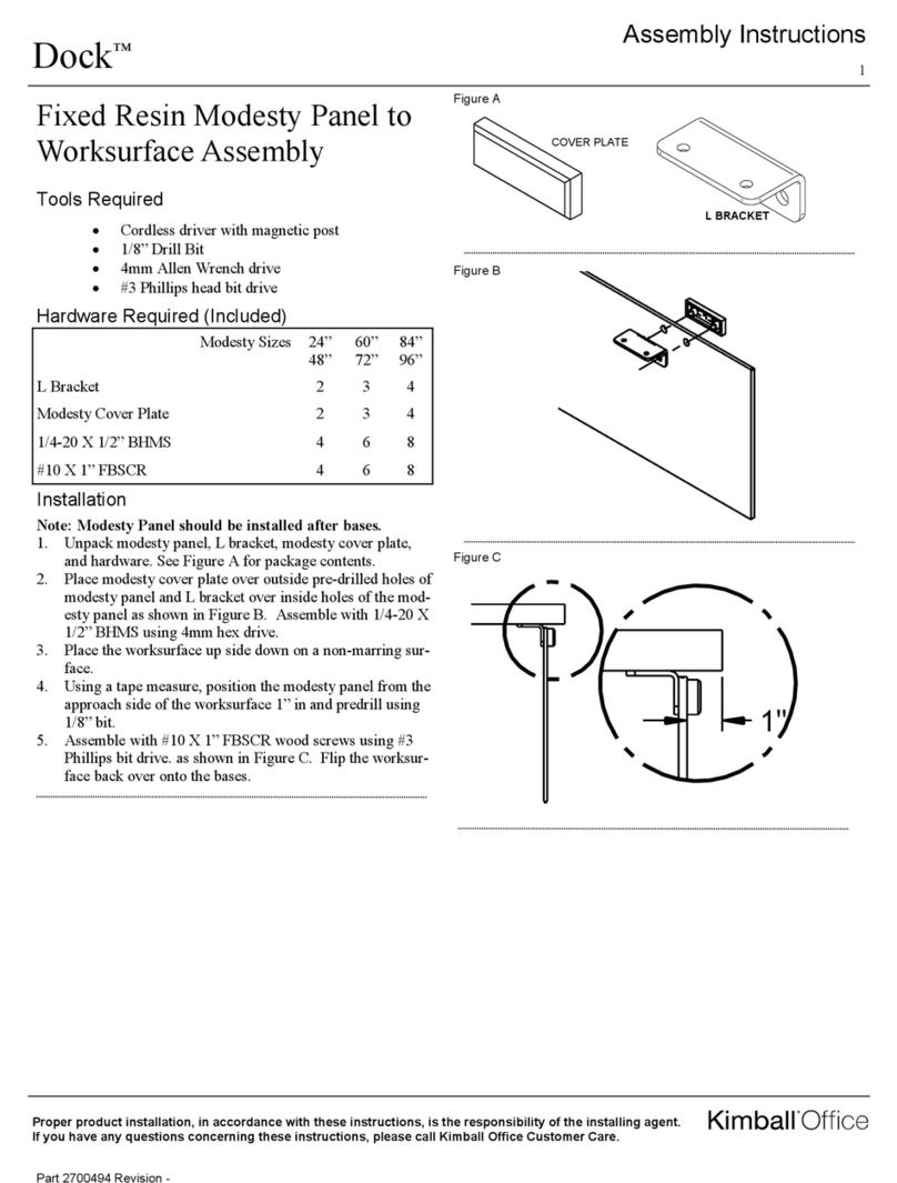
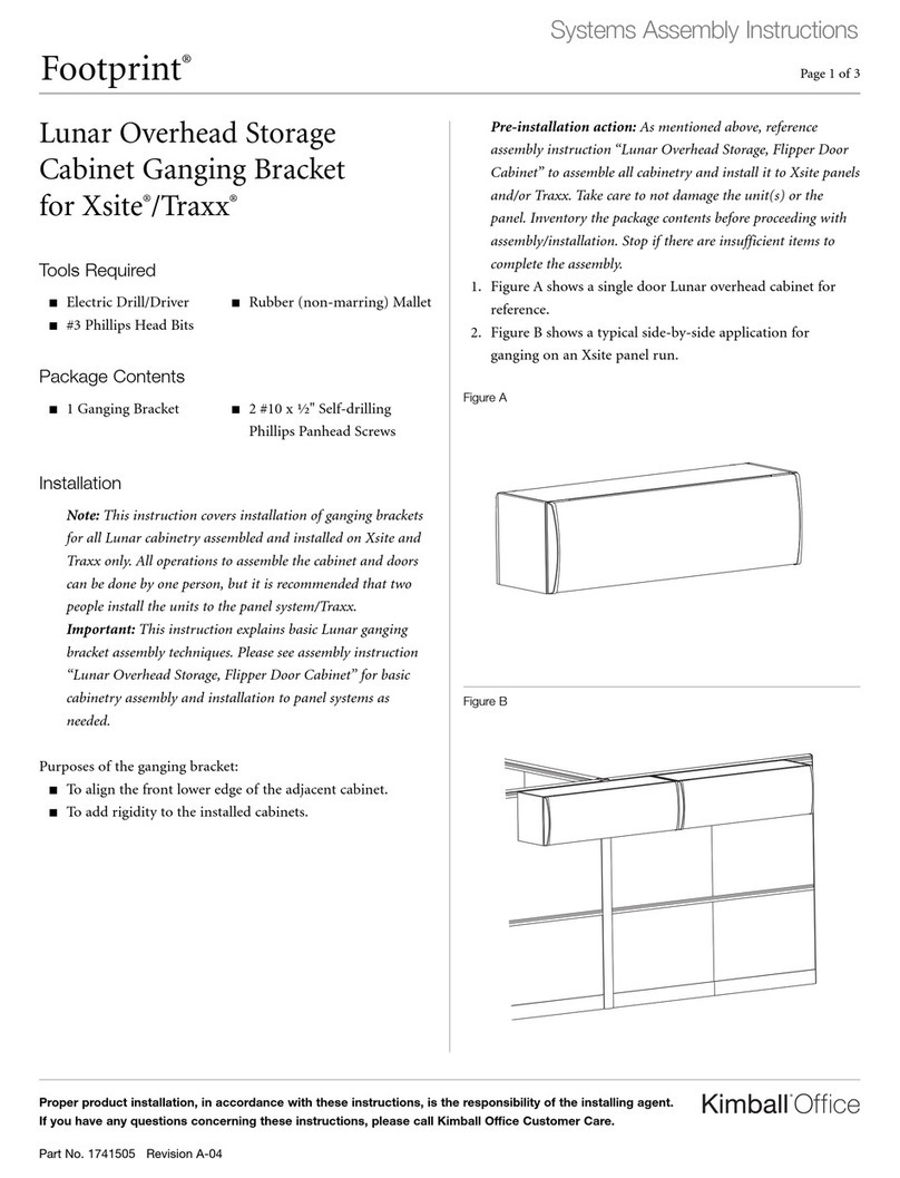
3. Place the folding bases on top of the worksurface in the
folded position. Using a tape measure, position the base
on the top as shown in figure A. A quick reference table
has been provided below in Table A for measurement
dimensions.
4. Mark and predrill the screw hole locations using a 1/8
inch bit 1/2” into the top. There should be a total of 20
holes drilled. 10 for each base plate. See Figure B.
5. If modesty, support rail, electrical trough, or electrical is
being installed to worksurface, see their respective As-
sembly instructions. Sequence the bases first, followed
by support rails, modesty panels, electrical trough, and
last electrical.
Figure A
Figure B
Top Sizes for Folding Bases AB
18” Depth x 48”-72” Width 1” 9”
18” Depth x 84-96” Width 7” 9”
18” Depth x 96” Width 13” 9”
24” Depth x 48”-72” Width 1” 12”
24” Depth x 84” Width 7” 12”
24” Depth x 96” Width 13” 12”
30” Depth x 48”-72” Width 1” 15”
30” Depth x 84” Width 7” 15”
30” Depth x 96” Width 13” 15”
B
A A
A
13579
246810
Dock™3
Proper product installation, in accordance with these instructions, is the responsibility of the installing agent.
If you have any questions concerning these instructions, please call Kimball Office Customer Care.
Part 2700492, Revision -
Assembly Instructions
Fixed Shared Base to
Worksurface Assembly
Hardware Required
 Drill
 1/8” Drill Bit
 #3 Phillips Head Bit Drive
Tools Required
2– Worksurfaces
1– Fixed Shared Base
2– Flat Ganging Brackets
32 - #12 x 1 Large Pan Head Wood Screws
Installation
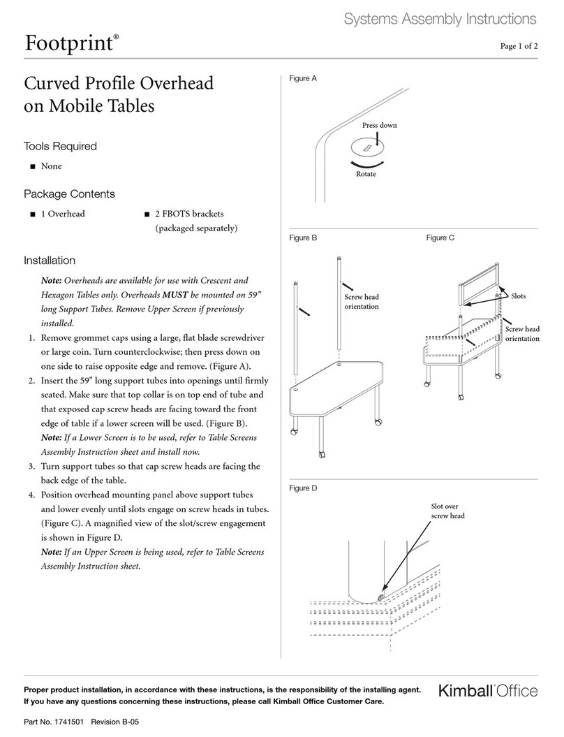
1. Unpack worksurfaces and place the first worksurface up
side down on a non-marring surface.
2. Unpack fixed shared base from box along with hardware
and flat ganging brackets. Install 1 standard base to the
outside of each worksurface. Refer to correct base locations
in the tables on page 1. See Figure A for package contents.
3. Positioning both worksurfaces together and using a tape
measure, place the shared base on the top as shown in Fig-
ure B. The base is centered from right to left. Note to make
sure the shorter foot is positioned on approach side of the
worksurface.
4. Using the same tape measure, position the flat ganging
brackets in their correct positions. They are positioned
center from right to left also. See Figure C.
5. Mark and predrill the screw locations using a 1/8” bit 1/2”
into the top for the base and flat brackets. There should be
a total of 32 holes drilled.
6. If modesty, support rail, electrical trough, or electrical is
being installed to worksurface, see their respective Assem-
bly instructions. Sequence the bases first, followed by sup-
port rails, modesty panels, electrical trough, and last elec-
trical.
7. Assemble flat brackets and base to first worksurface ON-
LY and flip over onto shared base.
8. Take the other worksurface and lay onto top of the base
and flat brackets and screw into place from pre-drilled
holes.
Top Sizes ABC
24” Depth 4-1/4” 3” 3”
30” Depth 7-1/4” 3” 3”
Figure D
Figure C
USER SIDE
APPROACH SIDE
B
C
Figure B
A
USER SIDE
APPROACH SIDE
Figure A
PACKAGE
CONTENTS
Konfig
Shared
C-Base
Shown
Fixed T or C leg
required
Dock™4
Proper product installation, in accordance with these instructions, is the responsibility of the installing agent.
If you have any questions concerning these instructions, please call Kimball Office Customer Care.
Part 2700492, Revision -
Assembly Instructions
Flip Nest Base to Worksurface
Assembly
Tools Required
Hardware Required
 Drill
 1/8” Drill Bit
 #3 Phillips Head Bit Drive
 #2 Phillips Head Bit Drive
1—Worksurface
1– Flip and Nest Base
20 - #12 x 1 Pan Head Wood Screws
8 - 1/4 - 20 x 1/2” Pan Head Machine Screws
Figure B
Figure A
1. Unpack worksurface and place up side down on a non-
marring surface.
2. Unpack Flip/Nest mechanism and legs. Note that these
will be in separate boxes and hardware will be taped
to the inside of the cartons.
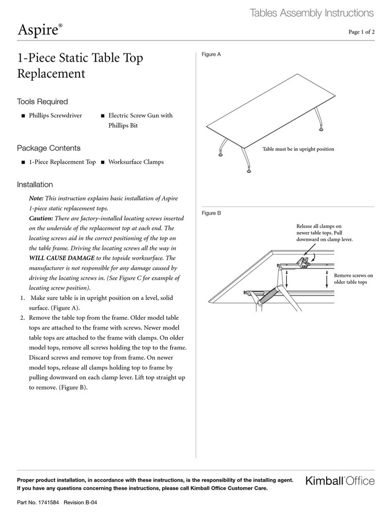
3. Place the flip and nest mechanism on top of the worksur-
face. Using a tape measure, position the mechanism on
the top as shown in figure A. A quick reference table has
been provided below in Table A for measurement dimen-
sions. Note that dimensions are to the pre-bored hole of
the base plate.
4. Mark and predrill the screw hole locations using a 1/8
inch bit 1/2” into the top. There should be a total of 20
holes drilled. 8 for each base plate of the mechanism and
4 for the handle. See Figure B.
5. Using a #3 Phillips head bit, and the #12 X 1” wood
screws provided, attach the mechanism and handle to the
worksurface. As shown in Figure B
6. With the mechanism in the closed position attach the legs
with the 1/4-20 machine screws provided. There will be 8
screws in total. See Figure C.
7. If modesty, support rail, electrical trough, or electrical is
being installed to worksurface, see their respective As-
sembly instructions. Sequence the bases first, followed
by support rails, modesty panels, electrical trough, last
and electrical.
8. Place and screw cable clamps down where see fit.
9. Flip table over and test that flip and mechanism locks in
both closed and open positions as shown in Figure D.
Installation
Figure C
Figure D
C
DETAILC
17
19
20
1 to 2
INCH SET BACK
18
A
12
34
B
DETAILB
56
7
8
12
2
1
3
4
56
78
CLOSED POSITION
OPEN POSITION
Worksurface Sizes AB
24” Width T Base 8 1/2” 1 1/2”
30” Width T Base 11 1/2” 1 1/2”
30” Width C Base 14 1/2” 1 1/2”
NON USER SIDE
A
B B

This manual suits for next models

3

Other Kimball Office Indoor Furnishing manuals
Kimball Office Aspire User manual

Kimball Office

Kimball Office Aspire User manual

Kimball Office Footprint Xsite User manual

Kimball Office

Kimball Office Footprint Xsite User manual

Kimball Office Fluent User manual

Kimball Office

Kimball Office Fluent User manual

Kimball Office Xsede Height Adjustable User manual

Kimball Office

Kimball Office Xsede Height Adjustable User manual

Kimball Office Fundamental User manual

Kimball Office

Kimball Office Fundamental User manual

Kimball Office Traditional Conference Table User manual

Kimball Office

Kimball Office Traditional Conference Table User manual

Kimball Office Xsede Height Adjustable User manual

Kimball Office

Kimball Office Xsede Height Adjustable User manual

Kimball Office Dock User manual

Kimball Office

Kimball Office Dock User manual

Kimball Office Aspire User manual

Kimball Office

Kimball Office Aspire User manual

Kimball Office Transcend Master Packet Complete Series User manual
Kimball Office

Kimball Office Transcend Master Packet Complete Series User manual

Kimball Office President User manual

Kimball Office

Kimball Office President User manual

Kimball Office Casegoods Priority User manual

Kimball Office

Kimball Office Casegoods Priority User manual

Kimball Office Aspire Table User manual

Kimball Office

Kimball Office Aspire Table User manual

Kimball Office Aspire User manual

Kimball Office

Kimball Office Aspire User manual

Kimball Office Xsede Height Adjustable User manual

Kimball Office

Kimball Office Xsede Height Adjustable User manual

Kimball Office Fundamental LF Series User manual

Kimball Office

Kimball Office Fundamental LF Series User manual

Kimball Office 2824569 User manual

Kimball Office

Kimball Office 2824569 User manual

Kimball Office Footprint 6"W Wardrobe User manual

Kimball Office

Kimball Office Footprint 6"W Wardrobe User manual

Kimball Office Footprint Bevel Profile Highback Organizer User manual

Kimball Office

Kimball Office Footprint Bevel Profile Highback Organizer User manual

Kimball Office President User manual

Kimball Office

Kimball Office President User manual

Kimball Office Aspire User manual

Kimball Office

Kimball Office Aspire User manual

Kimball Office Aspire User manual

Kimball Office

Kimball Office Aspire User manual

Kimball Office Interworks EQ User manual

Kimball Office

Kimball Office Interworks EQ User manual

Kimball Office KORE User manual

Kimball Office

Kimball Office KORE User manual
Popular Indoor Furnishing manuals by other brands

KidKraft ULTIMATE SPACESHIP Flight manual

KidKraft

KidKraft ULTIMATE SPACESHIP Flight manual

First Office intermix Assembly instructions

First Office

First Office intermix Assembly instructions

Whalen Bayside Furnishings Braeden CSC7PD-7 Assembly instructions

Whalen

Whalen Bayside Furnishings Braeden CSC7PD-7 Assembly instructions

Coopers G623 Instructions for use

Coopers

Coopers G623 Instructions for use

WASHTOWER WSCH26-45 Assembly instructions

WASHTOWER

WASHTOWER WSCH26-45 Assembly instructions

Room essentials 249-05-0418 Assembly instructions

Room essentials

Room essentials 249-05-0418 Assembly instructions

aspenhome I39-378 Assembly instructions

aspenhome

aspenhome I39-378 Assembly instructions

FMD Furniture BANDOL 1 668-001 Assembly instruction

FMD Furniture

FMD Furniture BANDOL 1 668-001 Assembly instruction

Pessotto Aladino Standard New 18 Assembly instructions

Pessotto

Pessotto Aladino Standard New 18 Assembly instructions

Rauch M1734 Assembly instructions

Rauch

Rauch M1734 Assembly instructions

FUFU & GAGA KF170295 Assembly instructions

FUFU & GAGA

FUFU & GAGA KF170295 Assembly instructions

Homelegance 1660BKT Assembly instruction

Homelegance

Homelegance 1660BKT Assembly instruction

OAKWORKS Spa OAKWORKS ProLuxe Series user manual

OAKWORKS Spa

OAKWORKS Spa OAKWORKS ProLuxe Series user manual

SIT&MORE COOL 8241/2503 Assembly Instructions Instruction Manual

SIT&MORE

SIT&MORE COOL 8241/2503 Assembly Instructions Instruction Manual

FOSFOR 2000100009 manual

FOSFOR

FOSFOR 2000100009 manual

Costway JV11305 manual

Costway

Costway JV11305 manual

Argos PAULO LARGE RECLINER 1454026 Assembly instructions

Argos

Argos PAULO LARGE RECLINER 1454026 Assembly instructions

Amerihome BSBNLSET Assembly instructions

Amerihome

Amerihome BSBNLSET Assembly instructions

manuals.online logo
manuals.online logoBrands
  • About & Mission
  • Contact us
  • Privacy Policy
  • Terms and Conditions

Copyright 2025 Manuals.Online. All Rights Reserved.