manuals.online logo
Brands
  1. Home
  2. •
  3. Brands
  4. •
  5. Kimball Office
  6. •
  7. Indoor Furnishing
  8. •
  9. Kimball Office Aspire Table User manual

Kimball Office Aspire Table User manual

Tables Assembly Instructions
Aspire®Page 1 of 5
Proper product installation, in accordance with these instructions, is the responsibility of the installing agent.
If you have any questions concerning these instructions, please call Kimball Office Customer Care.
Part No. 1741509 Revision A-05
Replacement of Gears in Folding
Table Center Mechanism
Tools Required
■Flat Head Screwdriver ■Long-Nose Pliers
■Rubber Mallet ■Set of metric Allen Wrenches
■Electric Screwdriver ■Lubriplate, Vaseline, or
with #4 Hex Drive other similar lubricant
Package Contents
■2 Gear (Left and Right) ■2 Pivot Ring
■2 Location Pin ■1 Male/Female Fastener
Installation
Note: These instructions provide basic information for
installing replacement gears in the folding table center
mechanism. For safety purposes and to avoid damage and/or
injury, it is recommended that two or more persons be used
to move the wood tops, and that the wood tops be removed/
installed with the base in the upright position.
Note: If a gear is being replaced at the end of the table, it will
not be necessary to remove the center heart mechanism as
outlined in steps 3, 4, 5, and 6. Follow steps 1 and 2, but
modify to remove the top only from the side that is being
replaced. Table will still need to be in folded position as per
step 2, but you will only be required to remove leg on one side
to replace gear. Continue with steps 7 through 17 as they apply
to this situation.
Note: For ease of replacement and re-assembly, gears should
only be replaced one side at a time. Determine which gear(s)
is/are damaged before starting repairs.
1. Make sure table is fully open and locked. Use the electric
screwgun with #4 hex bit to remove screws holding
worksurfaces to table frame. Save all removed screws.
(Reference Aspire Assembly Instruction: “Mount Wood
Top to Table Base Understructure”). Carefully remove
worksurfaces from frame and set aside. Unlock frame and
move to fully folded position. (Figure A).
Figure A
Figure B
“H” Bracket
Loosen retention
cable by removing
clevis pin
Fold frame
Unhook
spring
Remove worksurfaces
2. Use the long-nose pliers to remove the clevis pin from one
of the turnbuckles attached to the “H” bracket at the
bottom of the frame. Remove one of the springs from the
“H” bracket. Loosening these items removes tension from
the cables that pass through the center mechanism.
(Figure B).
Tables Assembly Instructions
Aspire
Proper product installation, in accordance with these instructions, is the responsibility of the installing agent.
If you have any questions concerning these instructions, please call Kimball Office Customer Care.
Part No. 1741509 Revision A-05
Page 2 of 5
Installation (continued)
3. Begin on the frame side of the first gear(s) to be replaced.
If the frame utilizes the “bayonet” style frame lock (with
orange button), it must be removed first to expose the
screws beneath it. (Figure C). Save all screws that attach lock
mechanism to rails. Remove and save all screws and washers
holding center “heart” mechanism and cable bars in place.
(Figure D).
4. Pull both rails loose and pivot them away from the center.
(Figure E).
5. Use an Allen Wrench to remove both set screws from the
bottom of the chrome-finished “heart”. Retain the set
screws. (Figure F).
Figure D
Figure F
Figure C
Figure E
Remove locking
mechanism
(if applicable)
Loosen rails and
rotate to side
Remove and
save screws
and washers
Remove
“heart”
set screws
Remove inner
machine screw
Caution: End of bar
will be loose when
outer machine screw
is removed.
Remove outer
machine screw
Remove lock
mechanism
Roller Bar
Chrome-finished “heart”
Tables Assembly Instructions
Aspire
Proper product installation, in accordance with these instructions, is the responsibility of the installing agent.
If you have any questions concerning these instructions, please call Kimball Office Customer Care.
Part No. 1741509 Revision A-05
Page 3 of 5
Installation (continued)
6. Pull “heart” away from center mechanism. Take care that no
other bars or cables are dislodged. (Figure G).
7. Use flat screwdriver and Allen Wrench to remove
Male/Female fastener from damaged gear. Discard fastener
pieces. (Figure H).
8. Remove damaged gear from center support tube. (Figure I).
9. Insert new pivot ring into recess in new replacement gear.
If necessary, tap ring lightly with rubber mallet to fully
seat ring into gear. Take care to not damage ring or gear.
Important: Gears in center mechanism MUST mesh
properly for correct folding action. Test fit, if necessary,
to make sure chosen replacement gear is an exact mirror
match of gear on opposite side of center rail. Improperly
matched gears will cause center mechanism malfunction and
could cause additional damage. (Figure J).
Figure H
Figure I
Figure G Figure J
Remove
Male/Female
Fastener
Remove old gear
Insert new pivot
ring into new gear
Important:
Make sure new gear is
exact mirror match of
opposite gear on rail
Carefully
remove heart
Tables Assembly Instructions
Aspire
Proper product installation, in accordance with these instructions, is the responsibility of the installing agent.
If you have any questions concerning these instructions, please call Kimball Office Customer Care.
Part No. 1741509 Revision A-05
Page 4 of 5
Installation (continued)
10. Remove old locating pins in center rail and replace with
new pins from package (two required). (Figure K).
Note: If opposite gear has already been replaced during this
work session, the locating pins are still good.
11. Apply small amount of Lubriplate, Vaseline or other similar
lubricant to center portion of support tube. Slide new
gear/ring assembly onto support tube and fully seat
assembly against center rail. Make sure assembly fully
engages locating pins. (Figure L).
Note: Re-check gear to make sure it is a match for the gear
on the opposite side of the rail.
12. Attach gear/ring assembly to center rail with new
male/female fastener. Fastener inserts into both sides of
center rail. Tighten fastener firmly, but do not over-tighten.
(Figure M).
13. Make sure all cabling and support bars are in their
approximate correct positions. Carefully match up holes
and recesses and re-install “heart” mechanism onto bars and
support tubes. Use rubber mallet to fully seat “heart” into
position. Re-install the two set screws in the bottom of the
“heart”. (Figure N).
Figure L
Figure N
Figure K
Figure M
Lubricate center
area of support
tube
Insert new
gear assembly
Attach Gear with
new Male/Female
Fastener
Make sure all cabling
is properly aligned
Re-install set screws
Re-install
“Heart”
Replace old locating
pins with new ones
Tables Assembly Instructions
Aspire
Printed in U.S.A. © 2005 Kimball International, Inc. T 800.482.1818 F 812.482.8300
Proper product installation, in accordance with these instructions, is the responsibility of the installing agent.
If you have any questions concerning these instructions, please call Kimball Office Customer Care.
Part No. 1741509 Revision A-05
Page 5 of 5
Installation (continued)
14. Rotate side rails upward and carefully re-install them into
original position on cable bars. Use original screws and
washers to firmly secure rails. If applicable, re-install
“bayonet” style frame lock to rails using saved screws.
(Figure O).
15. Re-fold table frame and re-attach spring and turnbuckle
clevis to “H” bracket. Use care while springs are re-tensioned.
(Figure P).
16. Carefully operate table mechanism to check for proper gear
mesh and bar operation with no binding or other obvious
malfunction. (Figure Q). If any gear(s) on opposite side of
frame must be replaced, repeat Steps 3 through 15.
17. Unfold table frame and lock into position. Take care to keep
hands out of frame “pinch-points” while unfolding. Re-attach
worksurfaces to frame using saved screws. (Figure R).
Figure P
Figure Q
Figure O
Operate mechanism to check
for proper gear mesh and bar
rotation with no binding
Re-attach
Spring
“H” Bracket
Re-attach
Turnbuckle
Figure R
Re-attach lock
mechanisms
(if applicable)
Re-attach rails
and all fasteners
Fully extend
and lock frame
Re-attach Worksurfaces

Other Kimball Office Indoor Furnishing manuals
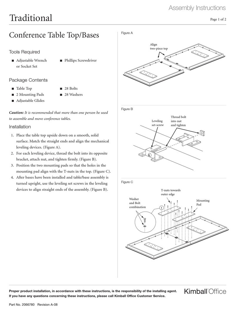
Kimball Office Footprint Bevel Profile Highback Organizer User manual

Kimball Office

Kimball Office Footprint Bevel Profile Highback Organizer User manual

Kimball Office President User manual

Kimball Office

Kimball Office President User manual

Kimball Office Casegoods President User manual

Kimball Office

Kimball Office Casegoods President User manual

Kimball Office 2824569 User manual

Kimball Office

Kimball Office 2824569 User manual

Kimball Office Footprint User manual

Kimball Office

Kimball Office Footprint User manual

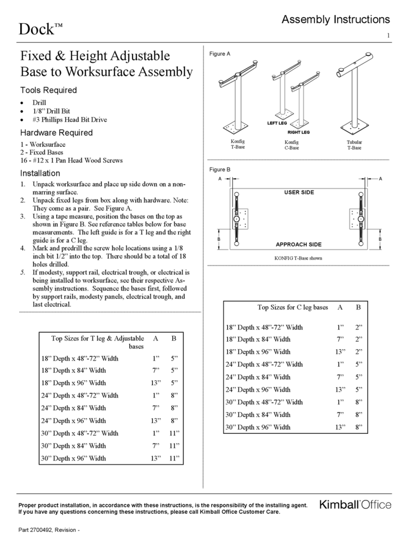
Kimball Office Traditional Conference Table User manual
Kimball Office

Kimball Office Traditional Conference Table User manual

Kimball Office Aspire User manual

Kimball Office

Kimball Office Aspire User manual
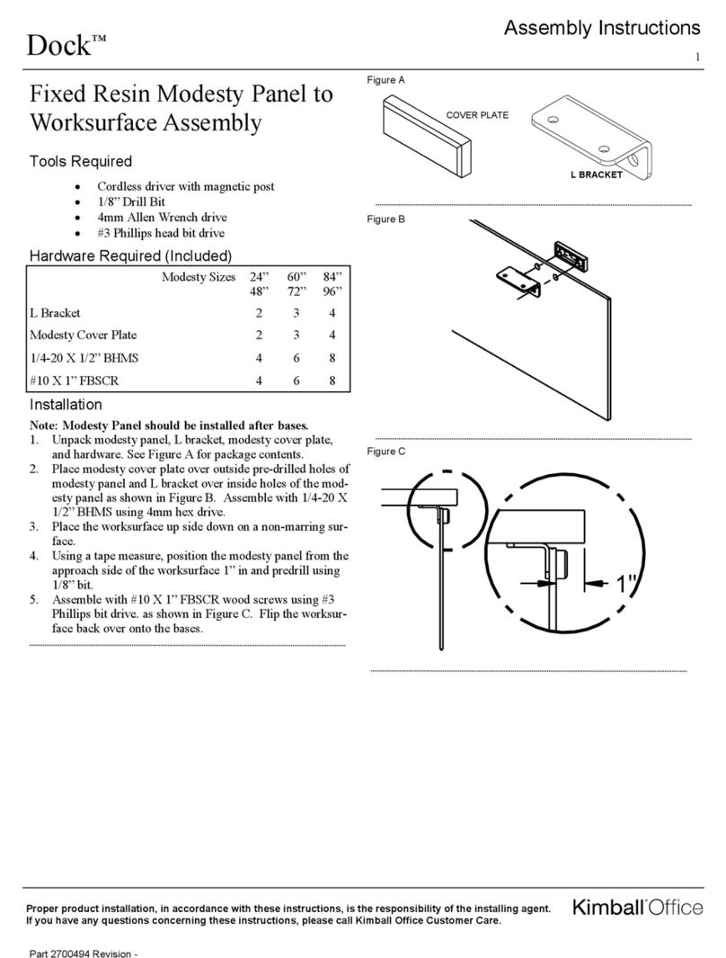
Kimball Office Innsbruck User manual

Kimball Office

Kimball Office Innsbruck User manual

Kimball Office Cetra/Interworks EQ Panel Attachment Brackets to Lunar... User manual

Kimball Office

Kimball Office Cetra/Interworks EQ Panel Attachment Brackets to Lunar... User manual

Kimball Office KORE User manual

Kimball Office

Kimball Office KORE User manual

Kimball Office Aspire User manual

Kimball Office

Kimball Office Aspire User manual

Kimball Office Transcend Master Packet Complete Series User manual

Kimball Office

Kimball Office Transcend Master Packet Complete Series User manual

Kimball Office Footprint User manual

Kimball Office

Kimball Office Footprint User manual

Kimball Office Fundamental User manual

Kimball Office

Kimball Office Fundamental User manual

Kimball Office Footprint User manual

Kimball Office

Kimball Office Footprint User manual

Kimball Office Definition 108 Highback Organizer User manual

Kimball Office

Kimball Office Definition 108 Highback Organizer User manual

Kimball Office KORE User manual

Kimball Office

Kimball Office KORE User manual

Kimball Office Aspire User manual

Kimball Office

Kimball Office Aspire User manual

Kimball Office Footprint User manual

Kimball Office

Kimball Office Footprint User manual

Kimball Office Fluent User manual

Kimball Office

Kimball Office Fluent User manual

Kimball Office Footprint User manual

Kimball Office

Kimball Office Footprint User manual

Kimball Office Villa User manual

Kimball Office

Kimball Office Villa User manual

Kimball Office Aspire User manual

Kimball Office

Kimball Office Aspire User manual

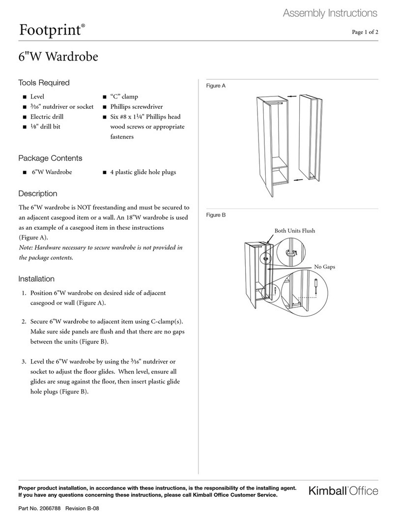
Kimball Office Xsede Height Adjustable User manual
Kimball Office

Kimball Office Xsede Height Adjustable User manual
Popular Indoor Furnishing manuals by other brands

Soltech Lounge Operator's manual

Soltech

Soltech Lounge Operator's manual

gbo SL1507 Assembly instructions

gbo

gbo SL1507 Assembly instructions

BRW S134-KOM2D4S/9/13 Assembly instructions

BRW

BRW S134-KOM2D4S/9/13 Assembly instructions

biodex 846 Installation & operation manual

biodex

biodex 846 Installation & operation manual

FMD Furniture BRISTOL 1XL 4020-101 Assembly instruction

FMD Furniture

FMD Furniture BRISTOL 1XL 4020-101 Assembly instruction

Bontempi Casa DELTA 53.27 Assembly instructions

Bontempi Casa

Bontempi Casa DELTA 53.27 Assembly instructions

realspace 7164892 manual

realspace

realspace 7164892 manual

Dorel Amerywood Industries 7600012 Assembly instructions

Dorel

Dorel Amerywood Industries 7600012 Assembly instructions

Core Products CRC508 manual

Core Products

Core Products CRC508 manual

Forte HRKR521L Assembly instructions

Forte

Forte HRKR521L Assembly instructions

INOSIGN Vitus 153 Assembly instructions

INOSIGN

INOSIGN Vitus 153 Assembly instructions

Polini kids Disney baby manual

Polini kids

Polini kids Disney baby manual

Whittier Wood Furniture 1506RGB Assembly instructions

Whittier Wood Furniture

Whittier Wood Furniture 1506RGB Assembly instructions

FIAM. Tango Quick start quide

FIAM.

FIAM. Tango Quick start quide

Furniture of America YNJ-15501C5-TV Assembly instructions

Furniture of America

Furniture of America YNJ-15501C5-TV Assembly instructions

Inspire NAPOLI 301-545GY Assembly instruction

Inspire

Inspire NAPOLI 301-545GY Assembly instruction

Lee & Plumpton 093 instructions

Lee & Plumpton

Lee & Plumpton 093 instructions

overstock 40288 Assembly instructions

overstock

overstock 40288 Assembly instructions

manuals.online logo
manuals.online logoBrands
  • About & Mission
  • Contact us
  • Privacy Policy
  • Terms and Conditions

Copyright 2025 Manuals.Online. All Rights Reserved.