Kolpin Outdoors 25-0600 User manual
Other Kolpin Outdoors Automobile Accessories manuals

Kolpin Outdoors
Kolpin Outdoors 35-5010 Setup guide
Kolpin Outdoors
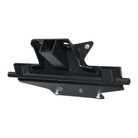
Kolpin Outdoors FRONT-CONNECT PLOW MOUNT KIT User manual

Kolpin Outdoors
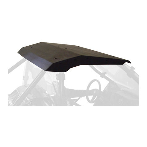
Kolpin Outdoors 34-9020 Installation and operating instructions
Kolpin Outdoors
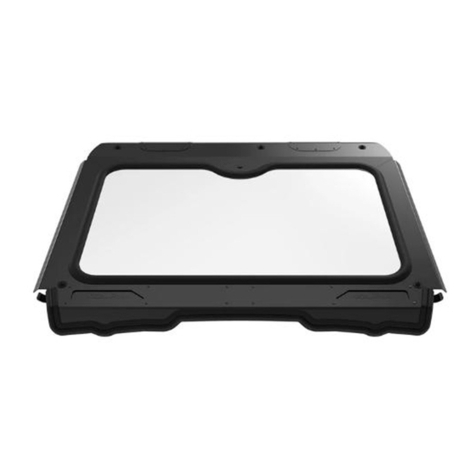
Kolpin Outdoors Arctic Cat Wildcat Roof Installation and operating instructions
Kolpin Outdoors
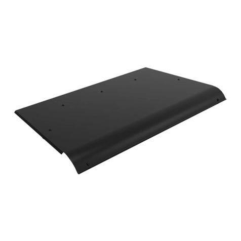
Kolpin Outdoors Polaris RZR Pro XP Installation and operating instructions

Kolpin Outdoors
Kolpin Outdoors 2721 Instruction sheet
Kolpin Outdoors
Kolpin Outdoors Polaris Ranger 570-6 / 800 Instruction sheet

Kolpin Outdoors
Kolpin Outdoors 20049 Instruction sheet
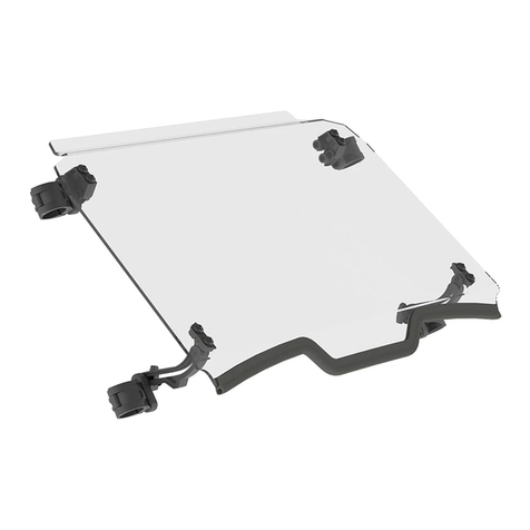
Kolpin Outdoors
Kolpin Outdoors 2754 Instruction sheet
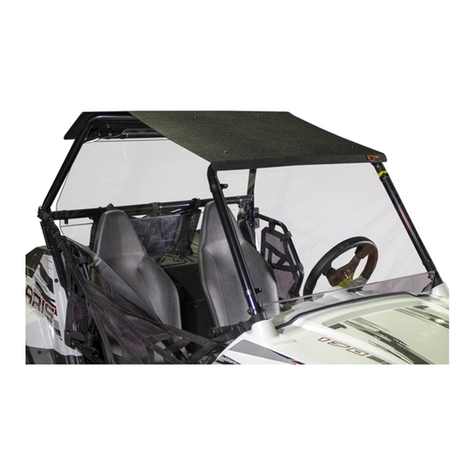
Kolpin Outdoors
Kolpin Outdoors YOUTH POLARIS RZR 170 COMBO KIT Installation and operating instructions
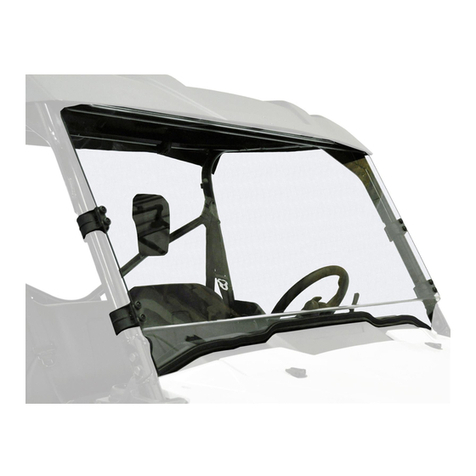
Kolpin Outdoors
Kolpin Outdoors 2786 Instruction sheet

Kolpin Outdoors
Kolpin Outdoors 25-1080 Installation and operating instructions
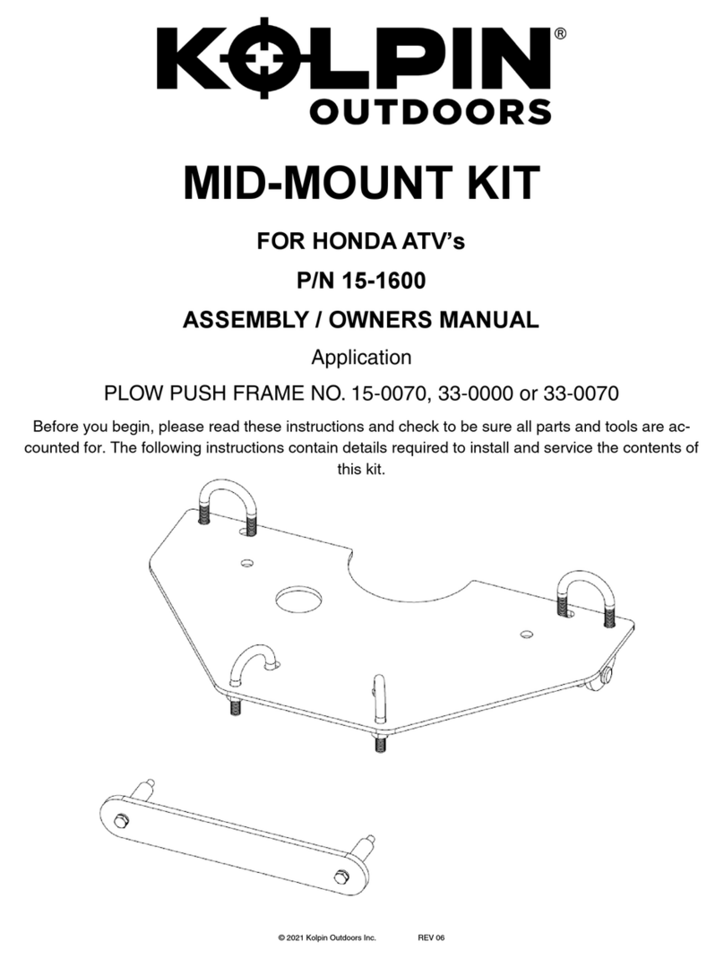
Kolpin Outdoors
Kolpin Outdoors 15-0070 Installation and operating instructions
Kolpin Outdoors
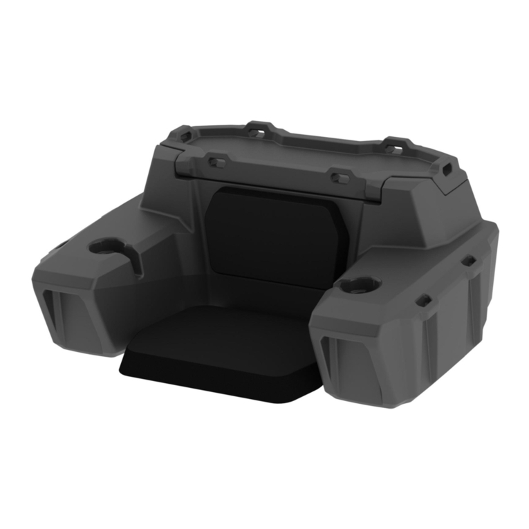
Kolpin Outdoors ATV Trunk & Lounger User manual

Kolpin Outdoors
Kolpin Outdoors 2732 User manual

Kolpin Outdoors
Kolpin Outdoors Rhino Grip XL - Double Instruction sheet

Kolpin Outdoors
Kolpin Outdoors 25-5310 Installation and operating instructions

Kolpin Outdoors
Kolpin Outdoors 26-1020 Instruction sheet

Kolpin Outdoors
Kolpin Outdoors 50-0360 User manual

Kolpin Outdoors
Kolpin Outdoors 25-8810 Installation and operating instructions
Popular Automobile Accessories manuals by other brands

ULTIMATE SPEED
ULTIMATE SPEED 279746 Assembly and Safety Advice

SSV Works
SSV Works DF-F65 manual

ULTIMATE SPEED
ULTIMATE SPEED CARBON Assembly and Safety Advice

Witter
Witter F174 Fitting instructions

WeatherTech
WeatherTech No-Drill installation instructions

TAUBENREUTHER
TAUBENREUTHER 1-336050 Installation instruction


