manuals.online logo
Brands
  1. Home
  2. •
  3. Brands
  4. •
  5. Lamp
  6. •
  7. Door Opening System
  8. •
  9. Lamp FD50-H User manual

Lamp FD50-H User manual

1
Thank you for selecting our product. Before starting installation, please read this manual thoroughly to ensure correct installation.
Please keep this manual at hand for future reference.
●This product is a parts set for an indoor sliding door system.
●
Provides the door with a two step soft motion in each
direction when opening and closing.
●Easy door installation and adjustment.
FD50-H SLIDING DOOR SYSTEM Installation Manual
(Two-Way Soft Close, Recessed Mount Roller )
Part No.FD50DHCP
When vertical frame is
not used, use a door
stopper.
Door height Max.2400 mm
2401‐2700 mm
Door width
680‐1500 mm 800‐1500 mm
Min.Door thickness 24 mm
Max.Door weight 50 kg / door
Height adjustable range 3 mm upward, 4 mm downward
Forward / backward
adjustment ±2 mm
WARNING: If not followed, death or serious injury may result.
Caution: If not followed injury or damage may result.
7KLVVOLGLQJGRRUV\VWHPVKRXOGEHLQVWDOOHGE\DTXDOL¿HGSHUVRQ,IWKHV\VWHPLVQRWLQVWDOOHGFRUUHFWO\WKHGRRUZLOOQRW
operate smoothly, and may cause injury.
,WLVQHFHVVDU\WRPDQXIDFWXUHWKHIUDPHZLWKVXI¿FLHQWVWUHQJWKVRWKDWLWHQGXUHVWKHZHLJKWRIWKHGRRUDQGDQ\LPSDFW
XSRQRSHQLQJFORVLQJWKHGRRU2QO\XVHGHVLJQDWHGVFUHZVDQGHQVXUHWKDWWKH\DUHIDVWHQHG¿UPO\$ IUDPHZLWKSRRU
strength or loose screws might result in the door falling and causing injury.
Do not try to use this product for anything other than its original purpose. Do not use any part for applications outside of its
VSHFL¿FDWLRQ
Do not disassemble nor modify any parts other than those described in this document.
0DNHVXUHWRIROORZWKHGHVLJQDWHGGLPHQVLRQVVSHFL¿FDWLRQVDQGKRUL]RQWDOYHUWLFDODQJOHV0DNHVXUHWKDWWKHIUDPHLV
not warped, since it may affect the movement of the door.
,IFXWWLQJDQ\SDUWVPDNHVXUHWRUHPRYHDQ\EXUUVEHIRUHLQVWDOODWLRQ$OVRFKHFNWKHXSSHUUDLOIRUDQ\OHIWRYHUEXUUVRU
scraps and remove these.
7KLVSURGXFWLVDSDUWIRUDUFKLWHFWXUDO¿WWLQJV$IWHULQVWDOODWLRQPDNHVXUHWRWHVWWKH¿QLVKHGSURGXFWWKRURXJKO\WRHQVXUH
WKDWLWLVZHOOIXQFWLRQLQJDQGVDIH
0DNHVXUHWRFKHFNWKHVFUHZVIRUVODFNDWUHJXODULQWHUYDOVRQHPRQWKIURP¿UVWXVDJHKDOID\HDUDQGWKHQRQHWLPH
every year is recommended).
・
The closing speed of the soft closing type door may change due to
ambient temperature, operating method or installation quality.
・
Recommended ambient temperature range is 5 to 40 ℃.
Prohibited
Warning
Caution Required
Meaning of symbols
FOR YOUR SAFE WORK AND CORRECT INSTALLATION
ABOUT THE PRODUCT
SPECIFICATION
2
No. ①②③④⑤⑥⑦
Name
Recessed roller soft loser
WZRZD\VRIWFORVH
Trigger,Jig Recessed roller Cover cap
Floor guide S
Upper track Door guide track
,WHP1R
)':5+'6&
)'75-)'75*
)':5+ )':5+&3 )'%* )'750
)'+%576,/
,WHP
$FFHVVRU\VFUHZ
Flat head tapping screw
3.8×40・・・・・・・3 pcs
$FFHVVRU\VFUHZ
Countersunk head
tapping screw
4×30・・・・・・・・・4 pcs
$FFHVVRU\VFUHZ
Pan head tapping screw
3.8×40・・・・・・・3 pcs 7KLFNQHVVPP
$FFHVVRU\VFUHZ
Binding head tapping
screw
4×16・・・・・・・・・5 pcs
YDULRXVVL]HV
+ROHSLWFKPP
3LWFKHQG PP
5HFRPPHQGHGVFUHZ
Countersunk head
tapping screw
4×20
+ROHSLWFKPP
3LWFKHQG PP
$FFHVVRU\VFUHZ
Pan head tapping screw
3.8×40
Single sliding
1 pc 1 set 1 pc 1 pc 1 pc 1 pc 1 pc
Double sliding
2 pcs 2 sets 2 pcs 2 pcs 2 pcs 2 pcs 2 pcs
,QOLQHVOLGLQJ
2 pcs 2 sets 2 pcs 2 pcs 2 pcs 1 pc 2 pcs
No. ⑧
237,21$/
3$576
No ⑨⑩⑪
Name Stopper block Name Door stopper
ÀRRUPRXQW
)ORRUJXLGH/ Spanner
,WHP1R
)'+6%
,WHP1R )'+7.< )'%* )')63
,WHP
,WHP
$FFHVVRU\VFUHZ
Bind head tapping screw
4×30・・・・・・・・・3 pcs
$FFHVVRU\VFUHZ
Binding head tapping
screw
4×16・・・・・・・・・・5 pcs
Single sliding
―
Double sliding
―
,QOLQHVOLGLQJ
1 pc
Trigger
2 pcs
Jig
1 pc
COMPONENT PARTS
INSTALLATION DRAWING (EXAMPLE)
(This describes installation of a single sliding door.)
24
2
15.6
8
48
15
16 51
17
R8
When stopper block is used
(2 sliding door, moving both directions)
22
6
1 3
5
7
4
35
21
35
51
Door end when fully shut FW
16
28
10《24》
18
Door width DW
Single sliding : DW
−
414
Double sliding : DW+DN
−
414
※
Min:24
17
30
15
41
95
64
318
《32》
Rail pitch 300
Margin DN
Overlap DK
18
217
594.5
48
16
25
28
Door process dimensions
Groove process dimensions for recessed roller and floor guide.
Trigger mount hole 2×I5
Processing upper track
Door handle
Door end when fully closed
(sold separately)
I4.5
4×I4.5 4.5×9.5Elongated hole
Door backward
and forward
adjustment range
Door vertical
adjustment range
3
4Trigger mount hole 2×I5
Processing upper track
22
Dimensions in
《》
: When long shaft floor guide L (option) is used.
3
Correct set position Correct set position
φ6
Trigger catcher
OK
(Red colored part)
Incorrect set position
ASSEMBLY
PREPARATION AND INSTALLATION
1
3. Installing casing and built-in guide track
under door bottom
Firmly insert the casing into the pocket as shown,
fasten it with the provided screws.
,QVWDOOWKHJXLGHWUDFNXQGHUWKHGRRU
1. Cutting and drilling holes on upper track
Cut to suitable length. For cutting and drilling holes, refer
to the illustration below.
When cutting, reinforce the track to prevent deformation
at cut section.
2. Preparation of mounting parts
5HFHVVHGUROOHU3XOOXS OHYHUWRVHSDUDWH
main unit from casing.
:KHQGLPHQVLRQGRRUZLGWK':
is more than 100 mm, provide 4.5 mm
dia. hole at 30 mm from cut face.
5. Assembly of parts and installing upper track
$VVHPEOHWKHSDUWVLQRUGHUIURPWRZLWKFDUHRIGLUHFWLRQ
Tape around recessed roller and upper track to prevent the inserted parts
IURPIDOOLQJ7DNLQJFDUHRIWKHGLUHFWLRQRIWKH/HDGLQJHGJH7UDLOLQJHGJH
install the upper track to the upper frame.
9HUL¿FDWLRQEHIRUHLQVWDOOLQJWKHGXDOVRIWFORVHU
:LWKRXWYHUL¿FDWLRQWKHVHOIFORVLQJIHDWXUHPD\IDLO
,IWKHSRVLWLRQLVZURQJSXOOEDFNWKHWULJJHUFDWFKHUWRWKHFRUUHFWSRVLWLRQXVLQJ
a 6mm diameter round bar.
6. Trigger installation
$FFRUGLQJWRWKH³,QVWDOODWLRQ'UDZLQJ´VHFWLRQLQVWDOOWKHWULJJHUZLWKWKHSURYLGHGVFUHZV
PPIURPWKHOHDGLQJHGJHDQGGRRUZLGWK':PPIURPWKHWUDLOLQJHGJH
Screw in the screws vertically.
,IVFUHZKHDGLVSRVLWLRQHG
outside the trigger, poor function
may result.
3.
Remove the jig.
2.
Install trigger.
1.
Align trigger and mounting
jig with mount hole.
Operation of trigger mounting jig
7. Floor guide
,QVWDOOWKHIORRUJXLGH VRWKDWLWUHPDLQVEHWZHHQ WKHOHDGLQJDQG
trailing edges of the door when it is opened or closed.
Door width
DW−414
9
Cut side
930
9
9
217
2×hole,φ5
φ4.5
(Track mount hole)
2×hole,φ5
INSTALLATION DIMENSIONS FOR TRIGGER 2
Double sliding※
Single sliding
Please add the Margin DN to dimension for Trigger 2,
if you are using a protruding handle. Example shown Below.
DW
[Margin DN = 0 mm]
Installation dimension for
Trigger 2
Example [Margin DN = 70 mm]
※

For Double sliding only.
DW+DN-414 is the Installation
dimension for Trigger 2
1,000 586 656
1,100 686 756
1,200 786 856
1,300 886 956
1,400 986 1,056
1,500 1,086 1,156
8
8
DW-414
217
DN+8
DW-414+DN
(see right table)
217
DW-414+DN
(see right table)
DN+8
Margin DN
217
Door width DW = (FW+DK)/2
Margin DN
Door width DW = (FW+DN+DK)/2
Overlap DK
Overlap DK
Margin DN
(in track)
(in track)
Trigger1
Trigger2
Door end
when fully closed
Door end
when fully closed
Trigger2
Trigger1
Trigger2
Trigger1
Casing
Door guide track
(For process dimensions, please
refer to “Installation Drawing”.)
12
12
217
DW - 414
18 18
Leading edge Trailing edg
e
Trigger mount hole
Trigger mounting jig
90°
Trigger
Mounting
screws
90°
Out of straight
Correct installation
Out of straight
Correct installation
OK
OK
Door(Trailing edge)
32
Floor guide
下上
左
右
(This describes installation of a single sliding door.)
Main unit Casing
Lever
Recessed roller
Trailingedge
Leadingedge
Recessed roller soft closer
two-way soft close
Upper track
Trigger
4
SUGATSUNE KOGYO CO.,LTD  
Tokyo, JAPAN
Phone: +81 (0)3 3866 2260 E-mail:[email protected]
SUGATSUNE KOGYO (UK) LTD  
Reading, UK
Phone: +44 118 9272 955
 
E-mail:[email protected]
SUGATSUNE EUROPE GmbH  
Dusseldorf, GERMANY
Phone: +49 211 53812900
 
E-mail:[email protected]
SUGATSUNE SHANGHAI Co., LTD  
Shanghai, CHINA
Phone: +86 21 3632 1858  E-mail:[email protected]
Guangzhou, CHINA  
Phone: +86 20 6639 3552  E-mail:[email protected]
SUGATSUNE KOGYO INDIA PRIVATE LIMITED  
Mumbai, INDIA
Phone: +91 22 28314490/91 E-mail:[email protected]
SUGATSUNE AMERICA, INC  
California, USA
Phone: +1 310 329 6373 E-mail:[email protected]
Chicago, USA  
Phone: +1 312 461 1081
E-mail:[email protected].
SUGATSUNE CANADA, INC.  
Phone: +1 514 312 5267
E-mail:[email protected]
2018.10 0755-6
9HUL¿FDWLRQRIVOLGLQJGRRUFORVHURSHUDWLRQ
Slowly move the door toward the door head, and confirm that the
VOLGLQJGRRUFORVHUVWDUWVLWVIXQFWLRQDWDSSUR[PPEHIRUHWKHIXOO
FORVHSRVLWLRQ&DUU\RXWVLPLODUYHUL¿FDWLRQIRUWKHGRRUWDLOGLUHFWLRQ
:KHQWKHFORVHULVQRWZRUNLQJFRUUHFWO\UHIHUWRWKH³7URXEOHVKRRWLQJ´
section.
'RQRWFORVHWKHGRRUZLWKH[FHVVLYHIRUFH,WPD\FDXVHGDPDJHRUPDOIXQFWLRQ
of soft close mechanism.
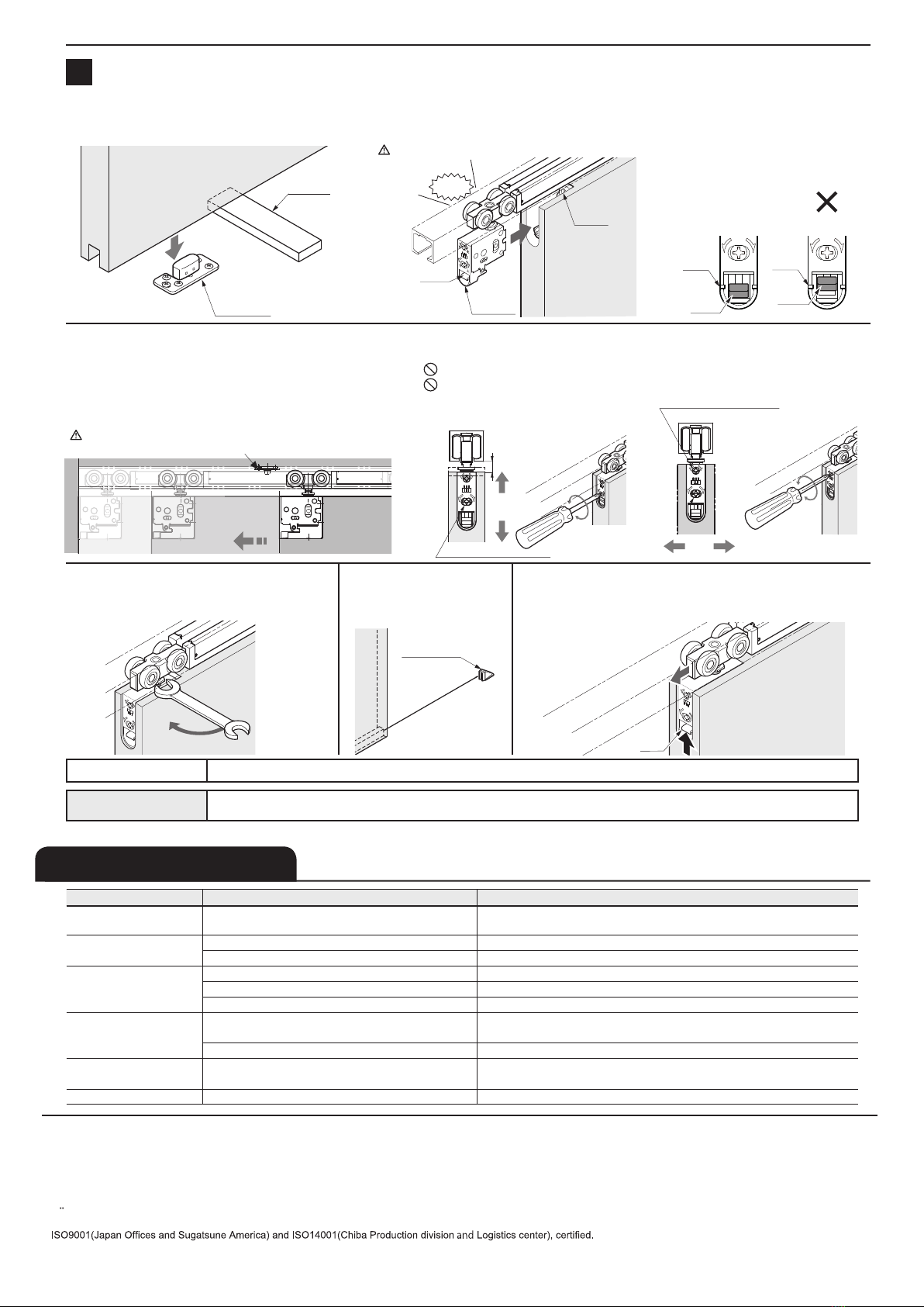
HANGING THE DOOR AND ADJUSTMENT
2
2. Door installation (top)
,QVHUWUHFHVVHGUROOHUPDLQXQLWLQWRGRRUVLGHFDVLQJDQGSXVKLQWKHORZHUHQGRIWKHUHFHVVHGUROOHUXQWLOD³FOLFN´VRXQGLVKHDUG
&RQ¿UPWKDWWKHOHYHULVSRVLWLRQHGDWWKHPDUNRQWKHUHFHVVHGUROOHUPDLQXQLWDVVKRZQ
Ensure that the roller main unit is securely attached to the casing.
1. Door installation (bottom)
3XWDPP VXSSRUWXQGHUWKHGRRU,QVHUWWKHIORRU
guide in the groove, and then hang the door.
右左
上
下
Vertical position adjustment screw
9
3
4
右
上
下
左
When removing the door
Use a 10 mm support under the door. Then pull out the
recessed roller main unit from the door while raising the lever.
4. Adjusting door position
AGMXVWWKHGRRUVXFKWKDWWKHGRRULVSDUDOOHOWRWKHXSSHUWUDFNZLWKPPFOHDUDQFHEHWZHHQWKHGRRUDQGÀRRU
Do not turn the adjustment screw more than the adjustment range.
To avoid damage of the adjustment screw, do not use electric screwdriver.
5. Fixing the jump prevention nut
With spanner 12, tighten the jump protect nuts until
they will contact to main unit.
When a vertical frame is not used,
install a door stopper.
Use door stopper of option.
22
右左
上
下
Forward / backward adjustment screw
右
上
下
左
Clockwise =Raise
&RXQWHUFORFNZLVH /RZHU
Trigger
右
上
下
左
Tighten
Vertical
DGMXVWPHQWUDQJHPP
Forward / backward
DGMXVWPHQWUDQJHPP
PERIODICAL INSPECTION
・Clean inside of track.
・&KHFNXSSHUVSDFHDQGORZHUVSDFHRIWKHGRRU,IQHFHVVDU\FRUUHFWWKHVSDFH
Trouble Check Solution
Door stops during soft
closing
&KHFNLIGRRUERWWRPFRQWDFWVZLWKÀRRU &RQ¿UPWKDWWKHWUDFN¿[LQJVFUHZVDUHQRWORRVHQHG7KHQDGMXVWGRRUKHLJKW
VXFKWKDWFOHDUDQFHEHWZHHQWKHGRRUERWWRPDQGÀRRULVPP
No soft closing Check if trigger is installed. ,QVWDOOWKHWULJJHUWRFRUUHFWSRVLWLRQ
Check if hook lock is used. Soft closer may not be able to close the door. Please contact Sugatsune.
$EQRUPDOQRLVHGXULQJ
operation
Check if door touches other parts. Provide necessary space between the door and adjacent objects.
Check track rollers for aluminum dust. Remove the track and pull out the roller. Then, clean the roller.
Check for loose screws retaining the upper track. Tighten the screw.
+HDY\GRRURSHUDWLRQ Check if door touches adjacent parts. Correct door position to avoid contact with other objects.
$GMXVWSRVLWLRQRIÀRRUJXLGHRUVWRSSHU
Check if the door is warped. Replace door with one that is not warped.
Door does not move. Check the track retaining screws for looseness. Roller touches the screw.
Retighten screws to free the roller.
Door starts to move. &KHFNLIWKHXSSHUWUDFNLVVHWKRUL]RQWDOO\ 8VLQJDOHYHOJDXJHUHVHWXSSHUUDLOKRUL]RQWDOO\
TROUBLESHOOTING
)LQDOYHUL¿FDWLRQ &RQ¿UPWKDWDOOVFUHZVDUHVHFXUHO\WLJKWHQHG$QGFRQ¿UPWKDWDOOVFUHZVKDYHEHHQXVHG
Floor guide
Support
Click
Lever
Main unit
Casing
右左
上
下
右左
上
下
Mark Mark
Lever Lever
OK
Correct lever position Incorrect lever position
Door stopper
(floor mount)
(option)
右
上
下
左
Lever

Other manuals for FD50-H

4

Other Lamp Door Opening System manuals

Lamp FD50-H User manual

Lamp

Lamp FD50-H User manual

Lamp XL-GC07D-CR User manual

Lamp

Lamp XL-GC07D-CR User manual

Lamp HC-70 User manual

Lamp

Lamp HC-70 User manual

Lamp HCZ-80 User manual

Lamp

Lamp HCZ-80 User manual

Lamp FD80-AFH User manual

Lamp

Lamp FD80-AFH User manual

Lamp KF28 User manual

Lamp

Lamp KF28 User manual

Lamp KF111-H User manual

Lamp

Lamp KF111-H User manual

Lamp MonoFlat FAD-5 User manual

Lamp

Lamp MonoFlat FAD-5 User manual

Lamp FD35EV User manual

Lamp

Lamp FD35EV User manual

Lamp FM150PRO User manual

Lamp

Lamp FM150PRO User manual

Lamp FD50-H User manual

Lamp

Lamp FD50-H User manual

Lamp LDD-S User manual

Lamp

Lamp LDD-S User manual

Lamp HDSN-30K User manual

Lamp

Lamp HDSN-30K User manual

Lamp FD50-H User manual

Lamp

Lamp FD50-H User manual

Lamp SLUN-N User manual

Lamp

Lamp SLUN-N User manual

Lamp FD35EV User manual

Lamp

Lamp FD35EV User manual

Lamp FD30EX User manual

Lamp

Lamp FD30EX User manual

Lamp FD80-H User manual

Lamp

Lamp FD80-H User manual

Lamp AZ-AT230-HL Instruction Manual

Lamp

Lamp AZ-AT230-HL Instruction Manual

Lamp FD30-F User manual

Lamp

Lamp FD30-F User manual

Lamp FD35EV User manual

Lamp

Lamp FD35EV User manual

Lamp FD35EV User manual

Lamp

Lamp FD35EV User manual

Lamp Lapcon J160 User manual

Lamp

Lamp Lapcon J160 User manual

Lamp FD50-H User manual

Lamp

Lamp FD50-H User manual

Popular Door Opening System manuals by other brands

Helm GT-L 80 H 412 installation instructions

Helm

Helm GT-L 80 H 412 installation instructions

Dorma 8600 Series manual

Dorma

Dorma 8600 Series manual

Von Duprin 33A Series Service manual

Von Duprin

Von Duprin 33A Series Service manual

Geofire Salamander System user's guide

Geofire

Geofire Salamander System user's guide

Yale UniTrol UNI-50BC Series installation instructions

Yale

Yale UniTrol UNI-50BC Series installation instructions

Falcon SC71 Series installation instructions

Falcon

Falcon SC71 Series installation instructions

Dorma ED700 Installation and Tune In Manual

Dorma

Dorma ED700 Installation and Tune In Manual

FAAC A100 Compact manual

FAAC

FAAC A100 Compact manual

RUSTICA Heavy-Duty Bypass Track System installation instructions

RUSTICA

RUSTICA Heavy-Duty Bypass Track System installation instructions

GAL MOVFE 2500 Electrical Manual

GAL

GAL MOVFE 2500 Electrical Manual

Olide 120B installation manual

Olide

Olide 120B installation manual

Chamberlain MyQ Garage user guide

Chamberlain

Chamberlain MyQ Garage user guide

Dorma 8600 TDE manual

Dorma

Dorma 8600 TDE manual

Eco ETS 64-R Mounting and operating instructions

Eco

Eco ETS 64-R Mounting and operating instructions

FAAC A140 AIR-T Series manual

FAAC

FAAC A140 AIR-T Series manual

LCN Benchmark III 9130 installation instructions

LCN

LCN Benchmark III 9130 installation instructions

Dormakaba ED900 installation instructions

Dormakaba

Dormakaba ED900 installation instructions

Dorma 8616 AFMJ manual

Dorma

Dorma 8616 AFMJ manual

manuals.online logo
manuals.online logoBrands
  • About & Mission
  • Contact us
  • Privacy Policy
  • Terms and Conditions

Copyright 2025 Manuals.Online. All Rights Reserved.