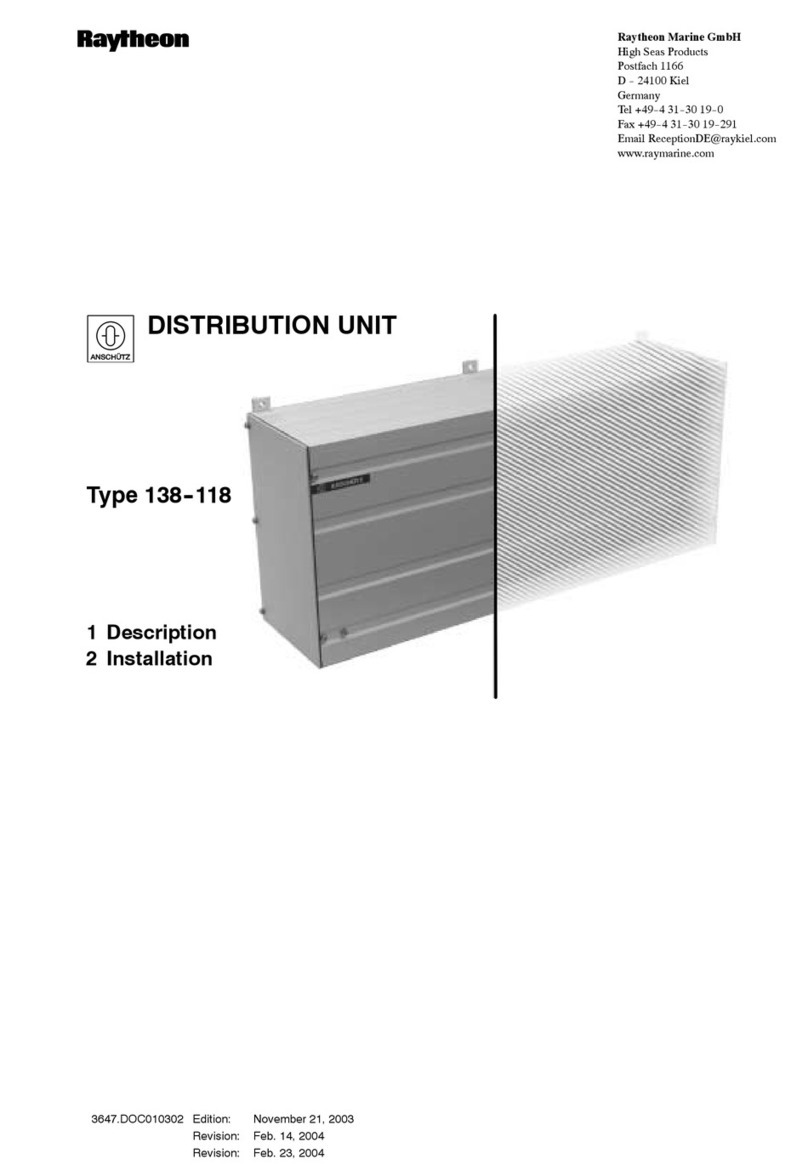
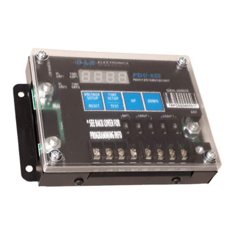
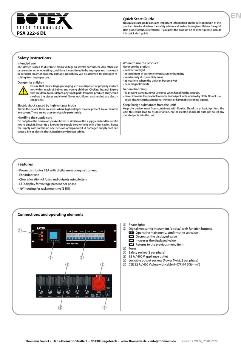
manuals.online logo
Brands
  1. Home
  2. •
  3. Brands
  4. •
  5. LEGRAND
  6. •
  7. Power Distribution Unit
  8. •
  9. LEGRAND 4 121 71 User manual

LEGRAND 4 121 71 User manual

1/7
87045 LIMOGES Cedex - FRANCE
Telephone : +33 (0)5 55 06 87 87 - Fax : +33 (0)5 55 06 88 88
Connected Contactor
Cat. number : 4 121 71 / 4 121 91
CONTENTS Pages
1. Description - Use .....................................1
2. Range..........................................................1
3. Overall dimensions...................................1
4. Preparation - Connection .......................1
5. General characteristics...........................6
6. Compliance and approvals .................... 7
7. Auxiliaries and accessories................... 7
1. DESCRIPTION - USE
Use:
Enables to remotely control (ON / OFF) loads (like water heater
swimming pool pomp, heaters, charging plug for electric cars…) by
smartphone with Home + Control app and / or by voice via a voice
assistant. This connected version also offers functions such as:
- Energy consumption: automatically energy consumption
information is available for the circuit to whom the connected
contactor is wired to.
- Scheduling: automatic opening and reclosing action scenarios
based on a timeline. (daily/weekly/specific event such as
“holidays”)
Technology:
. Connected contactor with control by single contact, via
smartphone, voice assistants and / or by its own push button on
the front.
Symbol :
2. RANGE
Noise level:
. Noiseless switch: <10bB.
Width:
. 1 module. 17.8 mm wide.
Types of contact:
. Normally open contact type
Rated current:
. 20 A
Rated voltage:
. 100 to 240V AC
Rated frequency:
. 50 / 60 Hz
Poles:
. 1 pole « NO »
2. RANGE
(continued)
Configuration and use:
. Can be used as a " standard " contactor not connected
And /Or
Can be used with:
- Legrand smartphone app
" HOME + CONTROL"
. Available for free on Google Play or App Store
- Voice assistants (compatible with the main voice
assistants of the market).
3. OVERALL DIMENSIONS
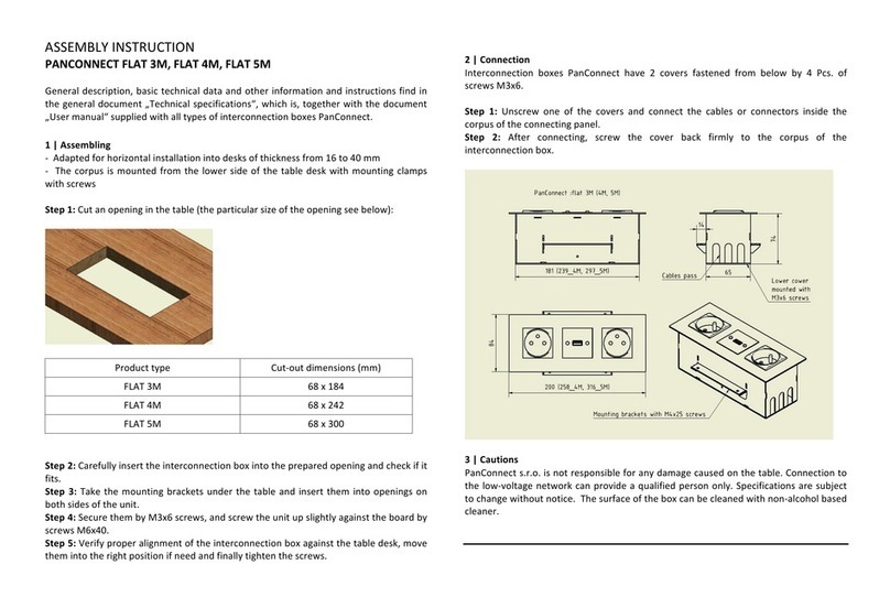
4. PREPARATION - CONNECTION
Mounting:
. On symmetrical rail EN / IEC 60715 or DIN 35.
Operating position:
. Vertical, Horizontal, Flat.
Technical data sheet: F03037EN/03
Updated on: 31/08/2020
Created on: 04/10/2019
Requires prior installation
of a “with Netatmo”
connected starter pack or
a Gateway module.
2/7
Connected Contactor
Cat. number : 4 121 71 / 4 121 91
4. PREPARATION - CONNECTION
(continued)
Row positioning:
. The product shape and the positioning of the terminals allow the
passage of single-line, three-lines and plug-in supply busbars in
the upper part of the product. Then, it is possible to freely choose
the position of the connected contactor in the row and to connect
by supply busbar the other devices put on the same DIN rail.
Module maintenance:
. It is possible to switch a connected contactor in the middle of a
row supplied with an upstream busbar without disconnecting the
other devices on the same DIN rail.
4. PREPARATION - CONNECTION
(continued)
Wiring of the upstream terminals:
In case of a remote control done via a wired push button, the
control is done either via C1 and C2 terminals.
Or via a push button through the phase line protected by a circuit
breaker on terminal C1
Warning: Do not wire from Neutral to C1 or C2
Wiring of the power supply and the load (downstream
terminals):
Technical data sheet: F03037EN/03
Updated on: 31/08/2020
Created on: 04/10/2019
1. Unclip the
clamp to put it in
open position
2. Unscrew the
terminals and pull
the device forward
in order to release
it from the DIN rail
3. Pull the device
downward in order to
completely release it
from the prongs of
the busbar
L: IN terminal for the
Line
N: IN terminal
for Neutral
Load : OUT terminal
for the line after
contact (towards Load)
C1 : IN terminal for control command (IN)
Free dry-contact. No power allowed.
C2 : Out terminal self-protected
Line for remote (OUT)
Free dry-contact. No power
allowed.
Advantage: «auto protected
terminals » technology. It is not
necessary to put a 2A protection
3/7
Connected Contactor
Cat. number : 4 121 71 / 4 121 91
4. PREPARATION - CONNECTION
(continued)
Electrical performance:
. Maximum resistive loads: 4800W
. Maximum motor loads: 2400VA
Wireless network:
. Maximum number of connected devices in the network: 100
Wiring diagrams:
«Auto protected terminals » technology. It is not necessary to put
a 2A protection.
. Installation controlled by the energy supplier electric meter:
. Installation for electrical motor:
. Installation for charging electric cars:
4. PREPARATION - CONNECTION
(continued)
Wiring diagrams
(continued)
:
. Control of heaters through an already installed central remote:
. Cabling in a swimming pool control cabinet:
. Control of a single line standard contactor (>20A):
. Control of a three lines standard contactor (>20A):
Technical data sheet: F03037EN/03
Updated on: 31/08/2020
Created on: 04/10/2019
4/7
Connected Contactor
Cat. number : 4 121 71 / 4 121 91
4. PREPARATION - CONNECTION
(continued)
Recommended tools:
. For the terminals: screwdriver Pozidriv n°1 or flat-blade 4 mm.
. For clamping: screwdriver flat-blade (5,5mm or less) or Pozidriv
n°1
Connection:
. Control and power screw terminals:
- Terminal type: cage
- Depth: 9 mm
- Stripping length recommended: 9 mm
- Screw head: Posidriv n°1 or slotted
- Type of screw: M3,5
- Minimum tightening torque: mini 0.8 Nm / maxi: 1.4 Nm
advised: 1 Nm
Conductor type for remote control terminals (C1, C2):
. Copper cables
Without ferrule
With ferrule
Rigid cable
1x (0.75 to 2.5mm²)
2 x (0.75 to 1.5mm²)
-
Flexible
cable
1x (0.75 to 2.5mm²)
2 x (0.75 to 1.5mm²)
1 x (0.75 to 2.5mm²)
2 x (0.75 to 1.5mm²)
Conductor type for power terminals (N, L, LOAD):
. Copper cables
Without ferrule
With ferrule
Rigid cable
1x (0.75 to 6mm²)
2 x (0.75 to 2.5mm²)
-
Flexible
cable
1x (0.75 to 6mm²)
2 x (0.75 to 2.5mm²)
1 x (0.75 to 2.5mm²)
2 x (0.75 to 1.5mm²)
Remote control commands:
. Operation on-site, directly with the front face push-button of the
device.
. Via the Home / Away wireless master switch
. Via smartphone with the Home + Control smartphone app
. By voice through a vocal assistant.
4. PREPARATION - CONNECTION
(continued)
Visualization of the operating mode of the device and
contacts:
. Via the LED, on the push button command
Color
Status
Meaning
OFF
Manual mode and opened
Contact (OFF)
Blue/Off
Slow blinking
Automatic mode and opened
Contact (OFF)
Blue/Green
Slow blinking
Automatic mode and closed
Contact (ON)
Vert
Fixed
Manual mode and closed
Contact (ON)
Visualization of the setup:
. Via the LED on the settings button
Color
Status
Meaning
Red
Fixed
Temporary status. Device not
connected to the radio network
Green
Fixed
Temporary status. Device correctly
paired to the radio network (when
the radio network is still open)
OFF
Normal status. Device paired to
the radio network (when the radio
network is closed)
Technical data sheet: F03037EN/03
Updated on: 31/08/2020
Created on: 04/10/2019
5/7
Connected Contactor
Cat. number : 4 121 71 / 4 121 91
4. PREPARATION - CONNECTION
(continued)
Add a connected contactor in a connected installation
(several steps)
(continued):
. 1/ Beforehand, to create a connected installation you must
install:
Either a gateway module
Or a connected starter pack (drawing of principle, works with
anykind of “with Netatmo”connected starter pack).
. 2/ Beforehand, the general circuit breaker must be turned OFF,
and only after wiring step done, can be powered back ON to
simultaneously power devices and allow them to be connected to
the network.
. 3/ Press and hold the gateway module settings button for more
than 3 seconds, OR in the center of the Home / Away wireless
master switch until the LED turns green, then release the button.
. The configuration LEDs of " ... with Netatmo " devices in the
installation must all light up in fixed green.
4. PREPARATION - CONNECTION
(continued)
Add a connected contactor in a connected installation
(several steps)
(continued):
. 4/ To complete the installation, briefly press the setting button
on the gateway module (or in the center of the Home / Away
wireless master switch) to finalize the installation.
All " ... with Netatmo " devices LED go OFF
Connected contactor resetting to remove it from a
connected installation
. Press and hold over 5 seconds on the setting button until the
LED on the setting button be fixed red. It is no longer paired with
the gateway module or the Home / Away wireless master switch
Other configurations & actions
. All other features and settings such as ; scenarios etc… are
directly explained step by step in the smartphone app.
Labelling:
. Circuit identification by way of a label inserted in the label
holder situated on the front of the product.
Technical data sheet: F03037EN/03
Updated on: 31/08/2020
Created on: 04/10/2019
6/7
Connected Contactor
Cat. number : 4 121 71 / 4 121 91
5. GENERAL CHARACTERISTICS
Marking of the connected contactor:
Markings of the front side :
Terminal markings :
Markings on the upper side
Lateral markings
5. GENERAL CHARACTERISTICS
(continued)
Sectioning distance:
. micro-gap construction contact according to the standard
EN 60669-2-1
Rated insulation voltage (Ui):
. Ui = 250 V~
Degree of pollution:
. 2
Rated impulse withstand voltage (Uimp):
. 4 kV
Influence of altitude :
. No influence up to 2 000 m
Assigned frequency :
. 50 / 60 Hz
Rated operational current (Ie) depending on utilization
category:
. AC-7a or AC1 (heaters) : le = 20 A
. AC-7b or AC3 (electric motors) : le = 10 A
Rated voltage of use (Ue):
. Ue = 100 to 240 V ~
Resistance to short-circuits:
. Presumed short circuit current 1500 A according to EN 60669-2-
1
. Thermal stress : 15 000 A²s to EN 60669-2-1
Recommendations:
. For the device protection against short circuits according to the
conditional current, it is recommended to use a circuit breaker or
fuse gG rated current  20 A.
Endurance:
. 20 000 000 operations without load
. 100 000 operations cycles AC-7a according to EN 61095
. 100 000 operations cycles AC-7b according to EN 61095.
. 10 000 operations under load SBL650W according to EN 60669-
2-1
. 200 000 operations under " resistive" load according to
EN 60669-2-5
Characteristics of the radio interface:
. Standard IEEE 802.15.4
. Frequencies 2,4 à 2,4835Ghz
. Transmitter output power <100mW
. Distance max between 2 radio devices: 50m in open field
Dielectric resistance :
. 2000V between front face and rail.
. 750V between upstream and downstream
Protection degree:
. Protection index of terminals against direct contacts: IP2X
(IEC/EN 60529)
. Protection index of the front face against direct contacts:
IP3XD (IEC/EN 60529)
. Class II, front panel with faceplate.
. Class of protection against mechanical impacts IK04 (IEC/EN
62262)
Technical data sheet: F03037EN/03
Updated on: 31/08/2020
Created on: 04/10/2019
up
down
Icon, to easily identify
a connected device in
the electrical panel
board
AX : Rated current for
externally ballasted lamp
loads and another rated
current
7/7
Connected Contactor
Cat. number : 4 121 71 / 4 121 91
5. GENERAL CHARACTERISTICS
(continued)
Vibrations and shaking resistance:
. vibrations : 10 to 55 to 10Hz single amplitude 0.75mm
. Shaking : 1000m / s ²(6 ±1ms)
Plastic material:
. Self-extinguishing polycarbonate.
. Heat and fire resistant according to IEC/EN 60669-2-1, glow-wire test at 960°C
. Classification UL 94 V0 (≥1.5mm)
Ambient operating temperature:
. Min. = - 5 °C Max. = + 45 °C.
Ambient storage temperature:
. Min. = - 40 °C Max. = + 70 °C.
Average weight:
. 78g
Volume when packed:
. 0,62 dm3.
Environmental profile:
. PEP document available
Installation software:
. XL PRO3
6. COMPLIANCE AND APPROVALS
Compliance to standards:
. NF EN 60669-2-1 / IEC 60669-2-1
Environment respect –Compliance with European Union Directives:
. Compliance with Directive 2002/95/EC of 27/01/03 known as "RoHS" which provides for a restriction on the use of dangerous
substances such as lead, mercury, cadmium, hexavalent chromium and polybrominated biphenyl (PBB) and polybrominated diphenyl
ether (PBDE) brominated flame retardants from 1st July 2006
. Compliance with the Directive 91/338/EEC of 18/06/91 and decree 94-647 of 27/07/04
. Compliant with regulation REACH
Conformity with electromagnetic interference (EMC):
. Compliant EN 301 489-1 , IEC 60669-2-5 , NF EN 60669-2-1
Immunity to shock waves
Radio transmission
Immunity to electrical transients in bursts.
Immunity to conducted disturbances induced by radio fields
Immunity to radiated fields
Electrostatic discharge immunity
Immunity to voltage dips and short break
. Compliance mission radiated according to NF EN55032.
Plastic materials:
. Halogen-free plastics.
. Marking of parts according to ISO 11469 and ISO 1043.
. ISO 7000: 2004, Graphical symbols to be used on equipment - Index and synopsis
Packaging:
. Design and manufacture of packaging in accordance with Decree 98-638 of 20/07/98 and Directive 94/62 / EC.
7. AUXILIARIES AND ACCESSORIES
Beforehand, requires the installation of a " connected starter pack " or " a “gateway module".

Technical data sheet: F03037EN/03
Updated on: 31/08/2020
Created on: 04/10/2019

This manual suits for next models

1

Other LEGRAND Power Distribution Unit manuals

LEGRAND 6 461 00-CTO User manual

LEGRAND

LEGRAND 6 461 00-CTO User manual

LEGRAND PLUGMOLD PM48TC User manual

LEGRAND

LEGRAND PLUGMOLD PM48TC User manual

LEGRAND 4 130 44 User manual

LEGRAND

LEGRAND 4 130 44 User manual

LEGRAND DPX3 1600 User manual

LEGRAND

LEGRAND DPX3 1600 User manual

LEGRAND Server Technology PRO3X User manual

LEGRAND

LEGRAND Server Technology PRO3X User manual

LEGRAND RARITAN PXE User manual

LEGRAND

LEGRAND RARITAN PXE User manual

LEGRAND HX3 125 A User manual

LEGRAND

LEGRAND HX3 125 A User manual

LEGRAND Server Technology PRO3X User manual

LEGRAND

LEGRAND Server Technology PRO3X User manual

LEGRAND PX3 User manual

LEGRAND

LEGRAND PX3 User manual

LEGRAND PDU User manual

LEGRAND

LEGRAND PDU User manual

LEGRAND Server Technology PRO3X User manual

LEGRAND

LEGRAND Server Technology PRO3X User manual

LEGRAND KEOR SPE R/T User manual

LEGRAND

LEGRAND KEOR SPE R/T User manual

LEGRAND PDU zero U User manual

LEGRAND

LEGRAND PDU zero U User manual

LEGRAND IME NEMO D4 - EC User manual

LEGRAND

LEGRAND IME NEMO D4 - EC User manual

LEGRAND 10'' User manual

LEGRAND

LEGRAND 10'' User manual

LEGRAND XL3 160 User manual

LEGRAND

LEGRAND XL3 160 User manual

LEGRAND HPM Electresafe REPC410 User manual

LEGRAND

LEGRAND HPM Electresafe REPC410 User manual

LEGRAND Raritan PX4 User manual

LEGRAND

LEGRAND Raritan PX4 User manual

LEGRAND CS102 User manual

LEGRAND

LEGRAND CS102 User manual

LEGRAND MP6-Megabreak User manual

LEGRAND

LEGRAND MP6-Megabreak User manual

LEGRAND Server Technology PRO4X User manual

LEGRAND

LEGRAND Server Technology PRO4X User manual

LEGRAND 0 734 54 User manual

LEGRAND

LEGRAND 0 734 54 User manual

LEGRAND Raritan PX3-1000 Series User manual

LEGRAND

LEGRAND Raritan PX3-1000 Series User manual

LEGRAND Arteor 5 735 49 User manual

LEGRAND

LEGRAND Arteor 5 735 49 User manual

Popular Power Distribution Unit manuals by other brands

Shure UA845 user guide

Shure

Shure UA845 user guide

Panamax M4400-20A Specifications

Panamax

Panamax M4400-20A Specifications

ITC T-6216 Operation manual

ITC

ITC T-6216 Operation manual

Blue Sea Systems PN 8618 Specification sheet

Blue Sea Systems

Blue Sea Systems PN 8618 Specification sheet

Minuteman RPM1581EV6 user manual

Minuteman

Minuteman RPM1581EV6 user manual

StarTech.com SATABAY5BK instruction manual

StarTech.com

StarTech.com SATABAY5BK instruction manual

Briteq PD-63SH Operation manual

Briteq

Briteq PD-63SH Operation manual

Citronic CPD-9 user manual

Citronic

Citronic CPD-9 user manual

Atlantis U power A03-PDUMBS-R Multilanguage manual

Atlantis

Atlantis U power A03-PDUMBS-R Multilanguage manual

PS Audio Power Director 4.7 Operation manual

PS Audio

PS Audio Power Director 4.7 Operation manual

Intellinet 164498 instructions

Intellinet

Intellinet 164498 instructions

Rock Solid RSM1-20AB-08N1 user guide

Rock Solid

Rock Solid RSM1-20AB-08N1 user guide

Essential Audio Tools Mains Multiplier Myni user manual

Essential Audio Tools

Essential Audio Tools Mains Multiplier Myni user manual

Tripp Lite SUDC208V42P60M Specifications

Tripp Lite

Tripp Lite SUDC208V42P60M Specifications

Show Tec PSA-32A6S manual

Show Tec

Show Tec PSA-32A6S manual

Murrelektronik MVK-MPNIO Series manual

Murrelektronik

Murrelektronik MVK-MPNIO Series manual

Tripp Lite PDUMH30HV quick guide

Tripp Lite

Tripp Lite PDUMH30HV quick guide

Tripp Lite PDUMV15-24 owner's manual

Tripp Lite

Tripp Lite PDUMV15-24 owner's manual

manuals.online logo
manuals.online logoBrands
  • About & Mission
  • Contact us
  • Privacy Policy
  • Terms and Conditions

Copyright 2025 Manuals.Online. All Rights Reserved.