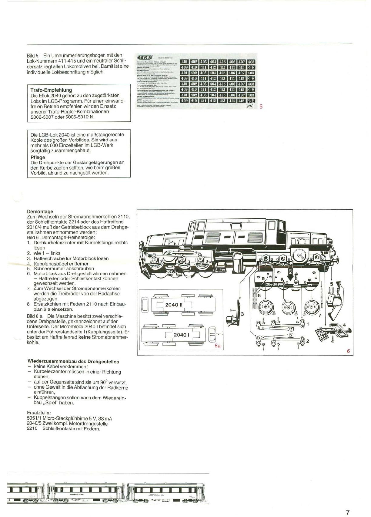
Oberleitung und Mehrzugbetrieb
Betriebsmöglichkeit für 2 Züge auf 1 Gleis
JI
0
1+
Haftreifenseite
("
T
1
®Masseschiene
IW~
~
;"!IQ&- ':""'::
~1IOCI3
~:
C
1
_....
_-.
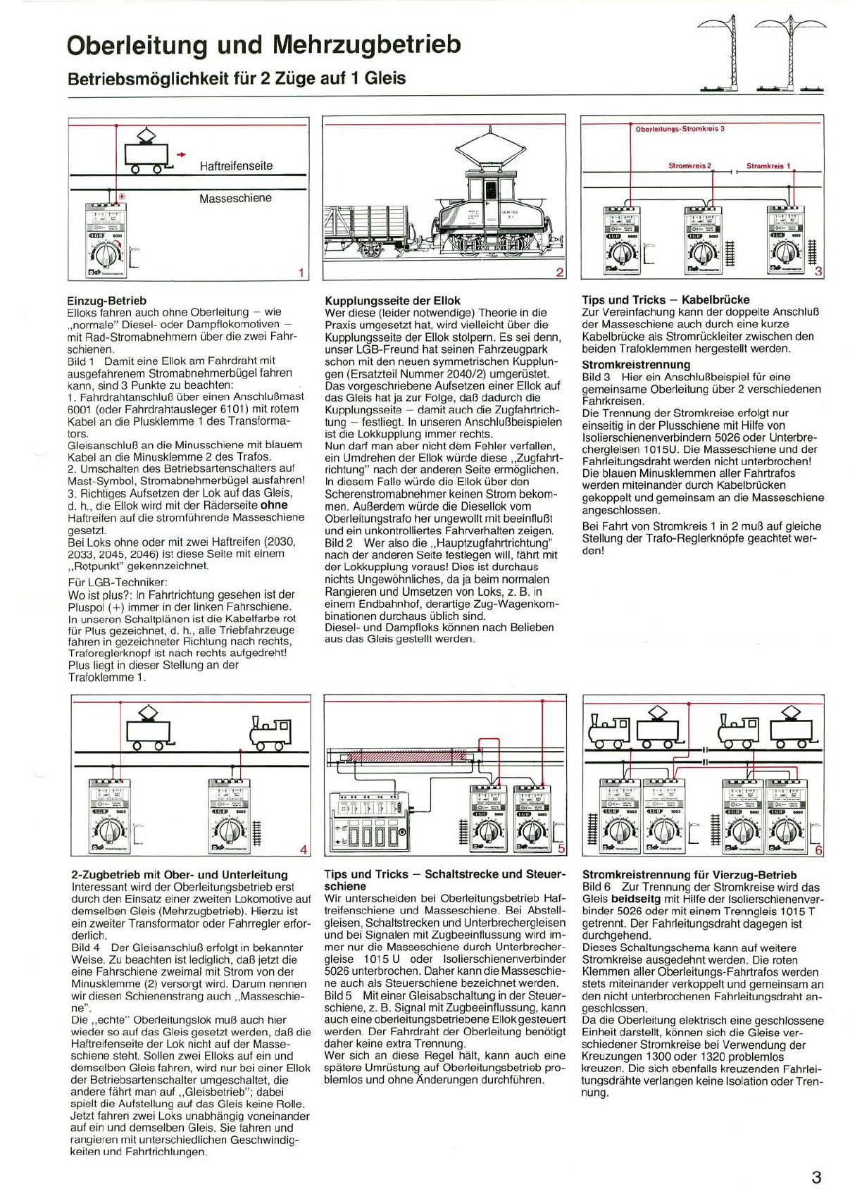
Einzug-Betrieb
ElloksfahrenauchohneOberleitung-wie
"normale"Diesel-oderDampflokomotiven-
mit Rad-Stromabnehmern über die zweiFahr-
schienen.
Bild1Damit eineEllokamFahrdraht mit
ausgefahrenem Stromabnehmerbügelfahren
kann,sind 3Punktezubeachten:
1.Fahrdrahtanschluß übereinenAnschlußmast
6001 (oderFahrdrahtausleger 6101) mit rotem
Kabelan diePlusklemme1des Transforma-
tors.
Gleisanschluß andieMinusschienemit blauem
Kabelan dieMinusklemme2des Trafos.
2. Umschaltendes Betriebsartenschaltersauf
Mast-Symbol,Stromabnehmerbügel ausfahren!
3. Richtiges AufsetzenderLokauf dasGleis,
d.h.,dieEllokwird mit derRäderseiteohne
Haftreifenauf diestromführendeMasseschiene
gesetzt.
Bei Loksohneoder mit zweiHaftreifen (2030,
2033,2045, 2046)ist diese Seitemit einem
"Rotpunkt" gekennzeichnet.
Für LGB-Techniker:
Wo ist plus?:In Fahrtrichtung gesehen ist der
Pluspol(+)immer in derlinkenFahrschiene.
In unserenSchaltplänenist dieKabelfarberot
für Plusgezeichnet,d.h.,alleTriebfahrzeuge
fahrenin gezeichneter Richtungnachrechts,
Traforeglerknopf istnach rechtsaufgedreht!
Plusliegt in dieserStellungander
Trafoklemme1.
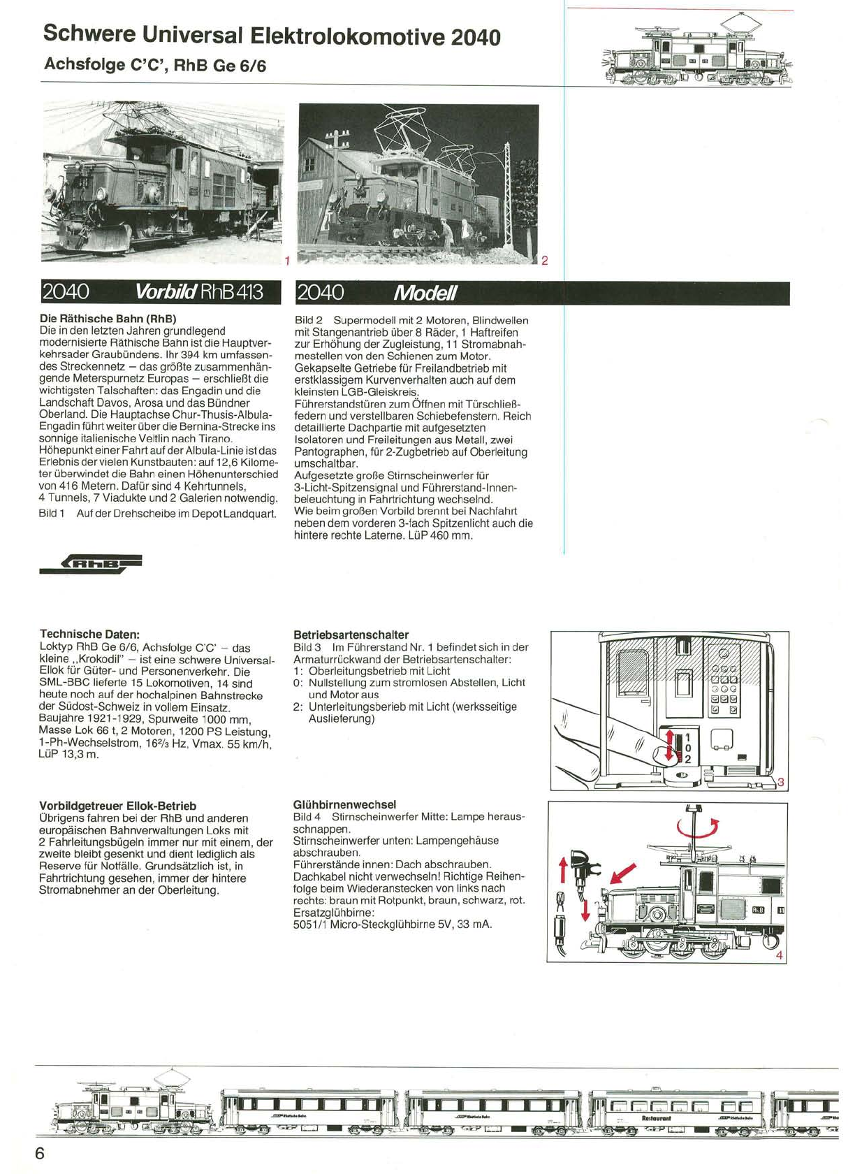
2-Zugbetrieb mit Ober-und Unterleitung
Interessant wird der Oberleitungsbetrieb erst
durchden Einsatz einerzweiten Lokomotive auf
demselben Gleis(Mehrzugbetrieb). Hierzu ist
ein zweiterTransformator oder Fahrregler erfor-
derlich.
Bild4DerGleisanschluß erfolgt in bekannter
Weise.Zubeachtenistlediglich,daßjetzt die
eineFahrschienezweimal mitStrom vonder
Minusklemme(2) versorgt wird.Darum nennen
wir diesenSchienenstrangauch"Masseschie-
ne".
Die"echte"Oberleitungslok muß auch hier
wieder so aufdasGleis gesetztwerden,daß die
HaftreifenseitederLok nicht auf derMasse-
schienesteht. Sollenzwei Elloksauf ein und
demselbenGleisfahren,wirdnur bei einer Ellok
derBetriebsartenschalter umgeschaltet,die
anderefährt manauf "Gleisbetrieb";dabei
spieltdieAufstellungauf das Gleiskeine Rolle.
Jetzt fahrenzweiLoksunabhängig voneinander
auf ein unddemselben Gleis.Siefahren und
rangieren mit unterschiedlichenGeschwindig-
keiten und Fahrtrichtungen.
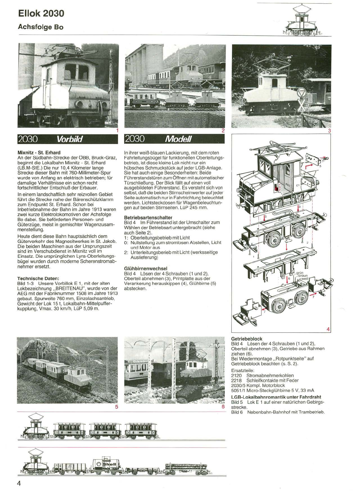
Kupplungsseite der Ellok
Werdiese (leider notwendige) Theorie in die
Praxis umgesetzt hat,wird vielleicht über die
Kupplungsseiteder Ellok stolpern.Es sei denn,
unser LGB-Freund hat seinen Fahrzeugpark
schon mit denneuen symmetrischen Kupplun-
gen (Ersatzteil Nummer 2040/2) umgerüstet.
Das vorgeschriebene Aufsetzen einer Ellok auf
das Gleis hat ja zur Folge,daß dadurch die
Kupplungsseite -damit auch die Zugfahrtrich-
tung ~festliegt. In unseren Anschlußbeispielen
ist die Lokkupplung immer rechts.
Nun darf man aber nicht dem Fehler verfallen,
ein Umdrehen der Ellok würde diese "Zugfahrt-
richtung"nach der anderen Seite ermöglichen.
In diesem Falle würde dieEllok über den
Scherenstromabnehmer keinen Strom bekom-
men. Außerdem würde die Diesellok vom
Oberleitungstrafo her ungewollt mit beeinflußt
und ein unkontrolliertes Fahrverhalten zeigen.
Bild 2 Wer also die "Hauptzugfahrtrichtung"
nach der anderen Seite festlegen will,fährt mit
der Lokkupplung voraus! Dies ist durchaus
nichts Ungewöhnliches,da ja beim normalen
Rangieren und Umsetzen von Loks,z. B. in
einem Endbahnhof,derartige Zug-Wagenkom-
binationendurchaus üblichsind.
Diesel-und Dampfloks können nach Belieben
ausdas Gleisgestellt werden.
2
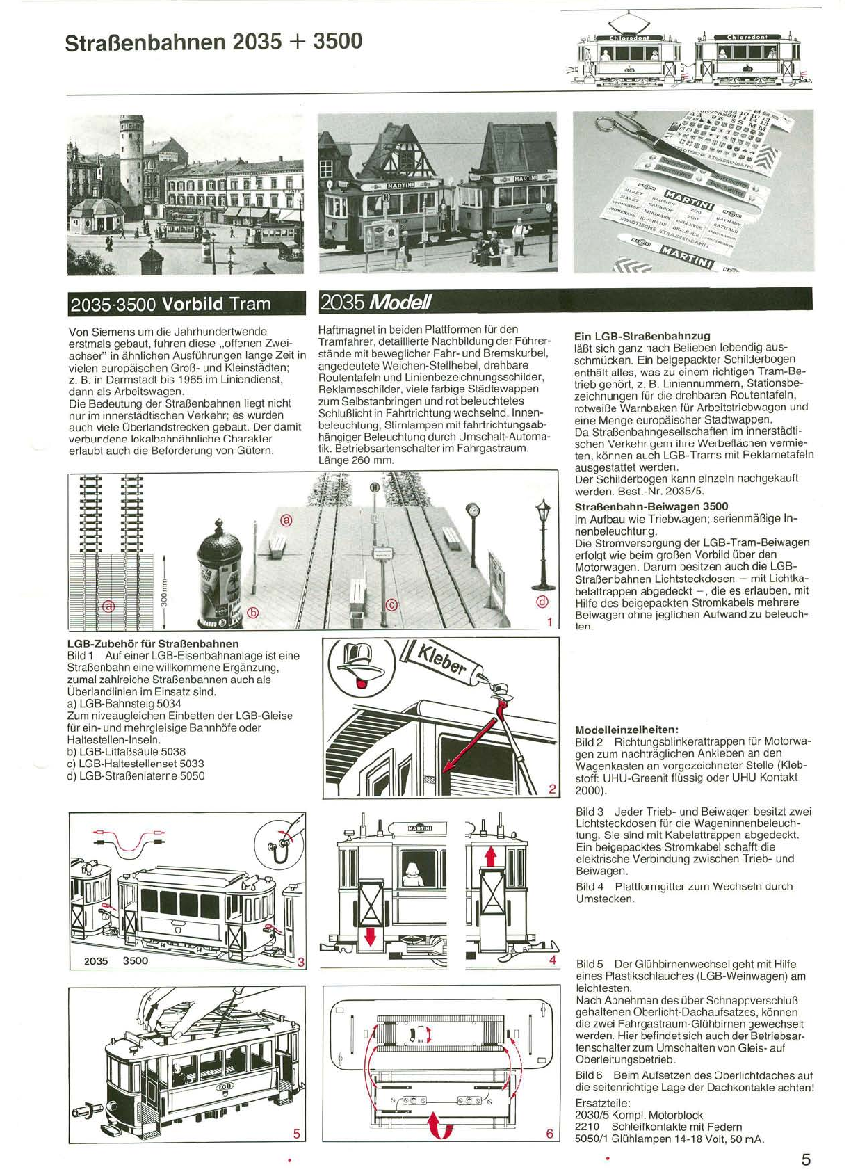
Oberleitungs-Stromkreis3
Tips und Tricks - Kabelbrücke
Zur Vereinfachung kann der doppelte Anschluß
der Masseschiene auch durch eine kurze
Kabelbrücke als Stromrückleiter zwischen den
beiden Trafoklemmen hergestellt werden.
Stromkreistrennung
Bild 3Hier ein Anschlußbeispiel für eine
gemeinsame Oberleitung über 2 verschiedenen
Fahrkreisen.
Die Trennung der Stromkreise erfolgt nur
einseitig in der Plusschiene mit Hilfe von
Isolierschienenverbindern 5026oderUnterbre-
chergleisen 1015U.DieMasseschiene und der
Fahrleitungsdraht werden nicht unterbrochen!
Die blauen Minusklemmen aller Fahrtrafos
werden miteinanderdurch Kabelbrücken
gekoppelt und gemeinsam an die Masseschiene
angeschlossen.
Bei Fahrt von Stromkreis 1 in 2 muß auf gleiche
Stellung der Trafo-Reglerknöpfe geachtet wer-
den!
4
Tips und Tricks - Schaltstrecke und Steuer-
schiene
Wir unterscheiden bei Oberleitungsbetrieb Haf-
treifenschiene und Masseschiene. BeiAbstell-
gleisen,Schaltstrecken und Unterbrechergleisen
und bei Signalen mit Zugbeeinflussung wird im-
mer nur dieMasseschiene durch Unterbrecher-
gleise 101 5 U oder Isolierschienenverbinder
5026 unterbrochen.Daher kann dieMasseschie-
neauchalsSteuerschiene bezeichnetwerden.
Bild 5Mit einer Gleisabschaltung in der Steuer-
schiene,z.B.Signal mit Zugbeeinflussung,kann
auch eineoberleitungsbetriebene Ellok gesteuert
werden.Der Fahrdraht der Oberleitung benötigt
daher keine extraTrennung.
Wersich an diese Regel hält,kann auch eine
spätereUmrüstung auf Oberleitungsbetrieb pro-
blemlos und ohne Änderungen durchführen.
Stromkreistrennung für Vierzug-Betrieb
Bild 6 Zur Trennung der Stromkreise wird das
Gleis beidseitg mit Hilfe der Isolierschienenver-
binder 5026 oder mit einem Trenngleis 1015 T
getrennt. Der Fahrleitungsdraht dagegen ist
durchgehend.
Dieses Schaltungschema kann auf weitere
Stromkreise ausgedehnt werden.Dieroten
Klemmen aller Oberleitungs-Fahrtrafoswerden
stets miteinander verkoppelt und gemeinsam an
den nicht unterbrochenen Fahrleitungsdraht an-
geschlossen.
Dadie Oberleitungelektrisch einegeschlossene
Einheit darstellt,können sich dieGleisever-
schiedener Stromkreise bei Verwendung der
Kreuzungen 1300 oder 1320 problemlos
kreuzen. Die sich ebenfalls kreuzenden Fahrlei-
tungsdrähte verlangenkeine Isolation oder Tren-
nung.
3