Makita DTW181 User manual

EN
Cordless Impact Wrench
INSTRUCTION MANUAL
4
PL
Akumulatorowy klucz
udarowy
INSTRUKCJA OBSŁUGI
10
HU
Akkumulátoros csavarkulcs
HASZNÁLATI KÉZIKÖNYV
17
SK
Akumulátorový razový
uťahovač
NÁVOD NA OBSLUHU
24
CS
Akumulátorový rázový
utahovák
NÁVOD K OBSLUZE
30
UK
Бездротовий ударний
гайковерт
ІНСТРУКЦІЯ З
ЕКСПЛУАТАЦІЇ
36
RO
Maşină de înşurubat cu
impact cu acumulator
MANUAL DE INSTRUCŢIUNI
43
DE
Akku-Schlagschrauber
BETRIEBSANLEITUNG
50

2

3
Fig.3
1
2
3
Fig.7
Fig.4
1
4
5
1
1
2
3
Fig.8

4
Fig.11
3
2
1
Fig.12

5 ENGLISH
ENGLISH (Original instructions)
SPECIFICATIONS
Model:
DTW181
Fastening capacities
Standard bolt
M8 - M16
High tensile bolt
M6 - M12
Square drive
12.7 mm
No load speed
Hard impact mode
0 - 2,400 min-1
Soft impact mode
0 - 1,300 min-1
Impacts per minute
Hard impact mode
0 - 3,600 min-1
Soft impact mode
0 - 2,000 min-1
Overall length
151 mm
Rated voltage
D.C. 18 V
Net weight
1.2 - 1.5 kg
•Due to our continuing program of research and development,
the specifications herein are subject to change without
notice.
•Specifications may differ from country to country.
•The weight may differ depending on the attachment(s), including
the battery cartridge. The lightest and heaviest combination, according to
EPTA-Procedure 01/2014, are shown in the table.
Applicable battery cartridge and charger
Battery cartridge
BL1815N / BL1820 / BL1820B / BL1830 / BL1830B / BL1840 /
BL1840B / BL1850 / BL1850B / BL1860B
Charger
DC18RC / DC18RD / DC18RE / DC18SD / DC18SE / DC18SF
•Some of the battery cartridges and chargers listed above
may not be available depending on your region of
residence.
WARNING: Only use the battery cartridges and chargers listed above. Use of any
other battery cartridges and chargers may cause injury and/or
fire.
Intended use
The tool is intended for fastening bolts and nuts.
Noise
The typical A-weightednoise level
determinedaccording to EN62841-2-2:
Sound pressure level (LpA) :
95 dB(A)
Sound power level (LWA) :
106 dB (A)
Uncertainty (K) : 3
dB(A)
WARNING: Wear ear protection.

6 ENGLISH
Vibration
The vibration total value (tri-axial
vector sum) determined
according to EN62841-2-2:
Work mode: impact tightening of
fasteners of the maxi-
mum capacity of the tool
Vibration emission (ah) : 10.5
m/s2
Uncertainty (K) : 1.5
m/s2
NOTE: The declared vibration emission value has
been measured in accordance with the standard test
method and may be used
for comparing one tool
with another.
NOTE: The declared vibration emission value may
also be used in
a preliminaryassessment
of exposure.
WARNING: The vibration emission during actual
use of the power tool can differ from the declared
emission value depending on the
ways in which the
tool is used.
WARNING: Be sure to
identify safety measures to
protect the operator that are based on an estimation
of exposure in the
actual conditions of use
(taking account of all
parts of the
operating cycle such as
the times when the tool is switched off and
when it is running idle in addition
to the trigger time).
EC Declaration of Conformity
For European countries only
The EC declarationof
conformity is included as
Annex A to this instruction
manual.
SAFETY WARNINGS
General power tool safety warnings
WARNING: Read all safety warnings,
instructions, illustrations and specifications
provided with this power tool. Failure to follow all
instructions listed below may result
in electric shock, fire
and/or serious injury.
Save all warnings and
instructions for future reference.
The term "power tool" in
the warnings refers to
your mains-operated (corded)
power tool or battery-
operated (cordless) power tool.
Cordless impact wrench safety
warnings
1. Hold the power tool by insulated gripping
surfaces, when performing an operation
where the fastener may contact hidden wiring.
Fasteners contacting a "live"
wire may make exposed
metal parts of the
power tool "live" and
could give the operator an electric shock.
2. Wear ear protectors.
3. Check the impact socket carefully for wear,
cracks or damage before installation.
4. Hold the tool firmly.
5. Keep hands away from rotating parts.
6. Always be sure you have a firm footing. Be
sure no one is below when using the tool in
high locations.
7. The proper fastening torque may differ
depending upon the kind or size of the bolt.
Check the torque with a torque wrench.
SAVE THESE INSTRUCTIONS.
WARNING: DO NOT let comfort or familiarity
with product (gained from repeated use) replace
strict adherence to safety rules for the subject
product.
MISUSE or failure to follow the safety rules stated
in this instruction manual may cause serious
personal injury.
Important safety instructions for
battery cartridge
1. Before using battery cartridge, read all
instructions and cautionary markings on (1)
battery charger, (2) battery, and (3) product
using battery.
2. Do not disassemble battery cartridge.
3. If operating time has become excessively
shorter, stop operating immediately. It may
result in a risk of overheating, possible burns
and even an explosion.
4. If electrolyte gets into your eyes, rinse them
out with clear water and seek medical

7 ENGLISH
attention right away. It may result in loss of
your eyesight.
5. Do not short the battery cartridge:
(1) Do not touch the terminals with any
conductive material.
(2) Avoid storing battery cartridge in a
container with other metal objects such
as nails, coins, etc.
(3) Do not expose battery cartridge to water
or rain.
A battery short can cause a large current flow,
overheating, possible burns and even a
breakdown.
6. Do not store the tool and battery cartridge in
locations where the temperature may reach or
exceed 50 °C (122 °F).
7. Do not incinerate the battery cartridge even if
it is severely damaged or is completely worn
out. The battery cartridge can explode in a
fire.
8. Be careful not to drop or strike battery.
9. Do not use a damaged battery.
10. The contained lithium-ion batteries are
subject to the Dangerous Goods Legislation
requirements.
For commercial transports e.g.
by third parties,
forwarding agents, special requirement on
packaging and labeling must be observed. For
preparation of the item being shipped, consulting
an expert for
hazardous material is required.
Please also observe possibly
more detailed national regulations.
Tape or mask off open contacts and pack up the
battery in such a
manner that it cannot
move around in the packaging.
11. Follow your local regulations relating to
disposal of battery.
12. Use the batteries only with the products
specified by Makita. Installing the batteries to
non-compliant products may result
in a fire,
excessive heat, explosion, or
leak of electrolyte.
SAVE THESE INSTRUCTIONS.
CAUTION: Only use genuine Makita batteries.
Use of non-genuine Makita batteries, or batteries that
have been altered, may result
in the battery
bursting causing fires,
personal injury and
damage. It will also
void the Makita
warranty for the Makita
tool and charger.
Tips for maintaining maximum
battery life
1. Charge the battery cartridge before
completely discharged. Always stop tool
operation and charge the battery cartridge
when you notice less tool power.
2. Never recharge a fully charged battery
cartridge. Overcharging shortens the battery
service life.
3. Charge the battery cartridge with room
temperature at 10 °C - 40 °C (50 °F - 104 °F).
Let a hot battery cartridge cool down before
charging it.
4. Charge the battery cartridge if you do not use
it for a long period (more than six months).
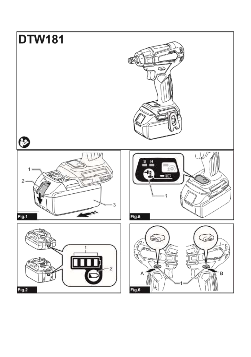
FUNCTIONAL
DESCRIPTION
CAUTION: Always be sure that the tool is
switched off and the battery cartridge is removed
before adjusting or checking function on the tool.
Installing or removing battery
cartridge
CAUTION: Always switch off the tool before
installing or removing of the battery cartridge.
CAUTION: Hold the tool and the battery
cartridge firmly when installing or removing
battery cartridge. Failure to hold
the tool and the
battery cartridge firmly may
cause them to slip
off your hands and
result in damage to
the tool and battery
cartridge and a
personal injury.
►Fig.1: 1. Red indicator 2. Button 3.
Battery cartridge
To remove the battery cartridge,
slide it from the
tool while sliding the button on the
front of the cartridge.
To install the battery cartridge,
align the tongue on

8 ENGLISH
the battery cartridge with
the groove in the
housing and slip it
into place. Insert it
all the way until
it locks in place
with a little click.
If you can see
the red indicator on
the upper side of
the button, it is
not locked completely.
CAUTION: Always install the battery cartridge
fully until the red indicator cannot be seen. If not, it
may accidentally fall
out of the tool,
causing injury to you
or someone around you.
CAUTION: Do not install the battery cartridge
forcibly. If the cartridge does
not slide in easily,
it is not being
inserted correctly.
Tool / battery protection system
The tool is equipped with
a tool/batteryprotection system.
This system automatically
cuts off power to
the motor to extend
tool and battery life.
The tool will
automatically stop during
operation if the tool
or battery is placed
under one of the following conditions:
Overload protection
When the battery is operated
in a manner that
causes it to draw
an abnormallyhigh current,
the tool automatically
stops without any
indication. In this situation,
turn the tool off and stop the
application that caused the tool to become overloaded.
Then turn the tool on to restart.
Overheat protection
When the tool/batteryis
overheated, the tool
stops automatically. In
this situation, let the
tool/batterycool before turning the
tool on again.
Overdischarge protection
When the battery capacity is
not enough, the tool
stops automatically. In
this case, remove the
battery from the tool
and charge the battery.
Indicating the remaining battery
capacity
Only for battery cartridges with the indicator
►Fig.2: 1. Indicator lamps 2. Check
button
Press the check button on
the battery cartridge to
indicate the remaining battery
capacity. The indicator lamps
light up for a few seconds.
NOTE: Depending on the conditions of use and the
ambient temperature, the
indication may differ slightly
from the actual capacity.
Switch action
►Fig.3: 1. Switch trigger
CAUTION: Before installing the battery
cartridge into the tool, always check to see that
the switch trigger actuates properly and returns
to the "OFF" position when released.
To start the tool, simply
pull the switch trigger.
Tool speed is
increased by increasing pressure
Indicator lamps
Remaining
capacity
Lighted
Off
Blinking
% to 100%
75
% to 75%
50
25
% to 50%
% to 25%
0
Charge the
battery.
The
ba
may
malfunctioned.

9 ENGLISH
on the switch trigger.
Release the switch trigger to stop.
NOTE: The tool automatically
stops if you keep
pulling the switch trigger for about 6
minutes.
Lighting up the front lamp
CAUTION: Do not look in the light or see the
source of light directly.
►Fig.4: 1. Lamp
►Fig.5: 1. Button
Pull the switch trigger to turn on the lamp. To turn off,
release it. The lamp goes
out approximately 10 seconds
after releasing the switch trigger.
To keep the lamp off, turn off the lamp status. First pull
and release the switch trigger. And then press the
button for one second within 10 seconds. To turn on
the lamp status again, press the button again similarly.
►Fig.7: 1. Hard 2. Soft 3. Reverse rotation
auto stop mode 4. Changed in three steps 5.
Button
Reversing switch action
NOTE: To confirm the lamp
status, pull the trigger.
When the lamp lights
up by pulling the
switch trigger, the lamp status is
ON. When the lamp does not come on, the lamp
status is OFF.
NOTE: When the tool is
overheated, the light
flashes for one minute,
and then the LED
display goes off. In
this case, cool down the tool before
operating again.
NOTE: Use a dry cloth
to wipe the dirt
off the lens of
the lamp. Be careful not to scratch the lens
of lamp, or it may lower the
illumination.
CAUTION: Always check the direction of
rotation before operation.
CAUTION: Use the reversing switch only after
the tool comes to a complete stop. Changing the
direction of rotation before the
tool stops may damage
the tool.
CAUTION: When not operating the tool,
always set the reversing switch lever to the
neutral position.
►Fig.6: 1. Reversing switch lever
This tool has a reversing switch to change the direction
of rotation. Depress the reversing switch lever fromthe
A side for clockwise rotation or from the B side for
counterclockwise rotation.
When the reversing switch lever is in the neutral
position, the switch trigger cannot be pulled.
Changing the impact force

10 ENGLISH
You can change the impact force in three steps: hard,
soft, and Reverse rotation auto stop mode.
This allows a tightening suitable to the work.
Every time the button is
pressed, the number of
blows changes in three steps.
The function of Reverse rotation auto stop mode works only
with pulling the trigger fully in counterclockwise tool
rotation. When the bolt/nut gets enough loosened, the tool stops the impact and rotation.
For approximately one minute after releasing the switch trigger,
the impact force can be changed.
Impact force grade displayed
on panel
Maximum blows
Purpose
Example of application
Hard
3,600 min-1 (/min)
Tightening when force and
speed are desired.
Assembling steel frames.
Soft
2,000 min-1 (/min)
Tightening when you
need fine
adjustment with
small
diameter bolt.
Assembling furniture.
Reverse rotation auto stop
mode
3,600 min-1 (/min)
Loosening with auto stop
function.
Disassembling bolts/nuts.
NOTE: Reverse rotation auto stop mode is available only when
the tool rotates counterclockwise. When rotating clockwise in Reverse
rotation auto stop mode, the impact force and speed are the same as Hard impact mode.
NOTE: When all lamps on the switch panel go out,
the tool is turned off to save the battery
power. The impact force grade can be checked by
pulling the switch trigger to the extent that the
tool does not operate.
NOTE: While pulling the switch trigger, the impact force grade cannot be changed.

11 ENGLISH
ASSEMBLY
CAUTION: Always be sure that the tool is
switched off and the battery cartridge is removed
before carrying out any work on the tool.
Selecting correct impact socket
Always use the correct size
impact socket for bolts
and nuts. An incorrect
size impact socket will
result in inaccurate and
inconsistent fastening torque and/or damage to the
bolt or nut.
Installing or removing impact
socket
Optional accessory
CAUTION: Make sure that the impact socket
and the mounting portion are not damaged before
installing the impact socket.
CAUTION: After inserting the impact socket,
make sure that it is firmly secured. If it comes out,
do not use it.
NOTE: The way of impact
socket installation varies
depending on the type
of the square drive
on the tool.
Tool with the ring spring
For impact socket without O-ring and
pin
►Fig.8: 1. Impact socket 2. Square drive 3.
Ring spring
Push the impact socket onto the square drive until it
locks into place.
To remove the impact socket,
simply pull it off.
For impact socket with O-ring and pin
►Fig.9: 1. Impact socket 2. O-ring 3. Pin
Move the O-ring out of the groove in the impact socket
and remove the pin from the impact socket. Fit the
impact socket onto the square drive so that the hole in
the impact socket is aligned with the hole in the square
drive.
Insert the pin through the hole in the impact socket and
square drive. Then return the O-ring to the original
position in the impact socket groove to retain the pin.
To remove the impact socket, follow the installation
procedures in reverse.
Tool with the detent pin
►Fig.10: 1. Impact socket 2. Hole 3.
Square drive
4. Detent pin
Align the hole in the side of the impact socket with the
detent pin on the square drive and push the impact
socket onto the square drive until it locks into place.
Tap it lightly if required.
To remove the impact socket,
simply pull it off. If
it is hard to remove, depress the
detent pin while pulling the impact socket.
Installing hook
CAUTION: When installing the hook, always
secure it with the screw firmly. If not, the hook
may come off from the
tool and result in
the personal injury.
►Fig.11: 1. Groove 2. Hook 3. Screw
The hook is convenient for
temporarilyhanging the tool. This can
be installed oneither side of the tool. To install the
hook, insert it into a groove in the tool housing on
either side and thensecure it with a screw. To remove,
loosen the screw and then take it out.
OPERATION
CAUTION: Always insert the battery cartridge
all the way until it locks in place. If
you can see the
red indicator on the upper side of the
button, it is not locked completely. Insert
it fully until the
red indicator cannot be
seen. If not, it
may accidentally fall
out of the tool,
causing injury to you
or someone around you.
►Fig.12
Hold the tool firmly and
place the impact socket over
the bolt or nut. Turn the tool on and fasten for the
proper fastening time.
The proper fastening torque may
differ depending upon the

12 ENGLISH
kind or size of
the bolt, the material
of the workpiece to be
fastened, etc. The relation between fastening torque
and fastening time is
shown in the figures.
Proper fastening torque for standard bolt
Proper fastening torque for high tensile bolt
1. Fastening time (second) 2.
Fastening torque
NOTE: Hold the tool pointed straight at the bolt or
nut.
NOTE: Excessive fastening torque may
damage the bolt/nut or
impact socket. Before starting
your job, always perform
a test operation to
determine the proper
fastening time for your
bolt or nut.
NOTE: If the tool is operated
continuously until the
battery cartridge has
discharged, allow the
tool to rest for
15 minutes before
proceedingwith a fresh
battery cartridge.
The fastening torque is affected
by a wide variety
of factors including the
following. After fastening, always
check the torque with a torque wrench.
1. Whenthe battery cartridge is
dischargedalmost completely,
voltage will drop and
the fastening torque will be
reduced.
1
N
m
(
kgf
cm)
2
20
(200)
40
(410)
60
(610)
80
(820)
100
(1020)
120
(1220)
140
(1430)
160
(1630)
180
(1840)
1
0
3
2
M16
M14
M12
M10
M8
M8
M10
M12
M14
M16
1.
Fastening time
(second)
2.
Fastening torque
1
0
3
2
2
N•m
(
kgf•cm
)
1
20
(200)
40
(410)
60
(610)
80
(820)
100
(1020)
120
(1220)
140
(1430)
160
(1630)
M12
M10
M8
M12
M10
M8
180
(1840)

13 ENGLISH
2. Impact socket
•Failure to use the
correct size impact socket
will cause a reduction in the fastening
torque.
•A worn impact socket
(wear on the hex
end or square end)
will cause a reduction
in the fastening torque.
3. Bolt
•Even though the torque
coefficient and the class
of bolt are the same, the proper fastening
torque will differ according to the diameter
of bolt.
•Even though the diameters of bolts are the
same, the proper fastening torque will differ
according to the torque
coefficient, the class of bolt
and the bolt length.
4. The use of the universal
joint or the extension
bar somewhat reduces the fastening
force of the impact wrench. Compensate
by fastening for a
longer period of time.
5. The manner of holding the tool or the material of
driving position to befastened will affect the
torque.
6. Operating the tool at low speed will cause a
reduction in the fastening torque.
MAINTENANCE
CAUTION: Always be sure that the tool is
switched off and the battery cartridge is removed
before attempting to perform inspection or
maintenance.
NOTICE: Never use gasoline, benzine, thinner,
alcohol or the like. Discoloration, deformation or
cracks may result.
To maintain product SAFETY and RELIABILITY,
repairs, any other maintenance
or adjustmentshould be
performed by Makita
Authorized or Factory Service
Centers, always using Makita
replacement parts.
OPTIONAL
ACCESSORIES
CAUTION: These accessories or attachments
are recommended for use with your Makita tool
specified in this manual. The use
of any other
accessories or attachments might present
a risk of injury to persons. Only
use accessory or
attachmentfor its stated purpose.
If you need any
assistance for more details
regarding these accessories,
ask your local Makita
Service Center.
•Impact socket
•Extension bar
•Universal joint
•Socket bit adapter
•Plastic carrying case
•Makita genuine battery and
charger
NOTE: Some items in the
list may be
included in the tool
package as standard
accessories. They may
differ from country to
country.

14 POLSKI
POLSKI (Instrukcja oryginalna)
DANE TECHNICZNE
Model:
DTW181
Zakresy dokręcania
Śruba zwykła
M8 –M16
Śruba o
dużej
wytrzymałości
M6 –M12
Zabierak kwadratowy
12,7 mm
Prędkość bez
obciążenia
Tryb dużej siły
udaru
0 –2 400 min-1
Tryb małej siły
udaru
0 –1 300 min-1
Liczba udarów na
minutę
Tryb dużej siły
udaru
0 –3 600 min-1
Tryb małej siły
udaru
0 –2 000 min-1
Długość całkowita
151 mm
Napięcie znamionowe
Prąd stały 18 V
Masa netto
1,2 –1,5 kg
•W związku ze stale prowadzonym przez naszą firmę programem
badawczo-rozwojowym niniejsze dane mogą ulec zmianom bez
wcześniejszego powiadomienia.
•Dane techniczne mogą różnić się w zależności od kraju.
•Masamoże być różna w zależności od osprzętu, w tym
akumulatora. W tabeli przedstawiona jest najlżejsza i
najcięższa konfiguracja, zgodnie z procedurą EPTA 01/2014.
Kompatybilne akumulatory i ładowarki
Akumulator
BL1815N / BL1820 / BL1820B / BL1830 / BL1830B / BL1840 /
BL1840B / BL1850 / BL1850B / BL1860B
Ładowarka
DC18RC / DC18RD / DC18RE / DC18SD / DC18SE / DC18SF
•Pewne z wymienionych powyżej akumulatorów i ładowarek
mogą być niedostępne w regionie zamieszkania
użytkownika.
OSTRZEŻENIE: Należy używać wyłącznie akumulatorów i ładowarek wymienionych powyżej.
Używanie innych akumulatorów i ładowarek może stwarzać ryzyko
wystąpienia obrażeń ciała lub pożaru.
Przeznaczenie
Narzędzie jest przeznaczone do
dokręcania śrub i nakrętek.
Hałas
Typowy równoważny poziom
dźwięku A określony w

15 POLSKI
oparciu o normę
EN62841-2-2: Poziom ciśnienia
akustycznego (LpA): 95
dB(A)
Poziom mocy akustycznej (LWA):
106 dB (A) Niepewność
(K): 3 dB(A)
OSTRZEŻENIE: Nosić ochronniki słuchu.
Drgania
Całkowita wartość poziomu drgań (suma
wektorów w 3 osiach)
określona zgodnie z normą
EN62841-2-2: Tryb pracy:
dokręcanie udarowe śrub i
wkrętów w maksymalnym
zakresie możliwości narzędzia
Emisja drgań (ah): 10,5 m/s2
Niepewność (K): 1,5 m/s2
WSKAZÓWKA: Deklarowana wartość
wytwarzanych drgań została
zmierzona zgodnie ze
standardową metodą testową
i można ją
wykorzystać do
porównywania narzędzi.
WSKAZÓWKA: Deklarowaną wartość
wytwarzanych drgań można
także wykorzystać we
wstępnej ocenie narażenia.
OSTRZEŻENIE: Drgania wytwarzane
podczas rzeczywistego
użytkowania elektronarzędzia
mogą się różnić od
wartości deklarowanej, w
zależności od sposobu jego
użytkowania.
OSTRZEŻENIE: W oparciu o
szacowanenarażenie w
rzeczywistych warunkach
użytkowania należy określić
środki bezpieczeństwa w
celu ochrony operatora
(uwzględniając wszystkie
elementy cyklu działania, tj.
czas, kiedy narzędzie jest
wyłączone i kiedy pracuje
na biegu jałowym, a
także czas, kiedy jest
włączone).
Deklaracja zgodności WE
Dotyczy tylko krajów europejskich
Deklaracja zgodności WE jest
dołączona jako załącznik A
do niniejszej instrukcji obsługi.
OSTRZEŻENIA
DOTYCZĄCE
BEZPIECZEŃSTWA
Ogólne zasady bezpiecznej
eksploatacji elektronarzędzi
OSTRZEŻENIE: Należy zapoznać się z
ostrzeżeniami dotyczącymi bezpieczeństwa,
instrukcjami, ilustracjami i danymi technicznymi
dołączonymi do tego elektronarzędzia.
Niezastosowanie się do
podanych poniżej instrukcji może
prowadzić do porażenia
prądem, pożaru i/lub
poważnychobrażeń ciała.
Wszystkie ostrzeżenia i
instrukcje należy zachować do
wykorzystania w przyszłości.
Pojęcie „elektronarzędzie", występujące
w wymienionych tu
ostrzeżeniach, odnosi się
do elektronarzędzia
zasilanego z sieci
elektrycznej (z
przewodem zasilającym)
lub do elektronarzędzia
akumulatorowego (bez przewodu
zasilającego).
Ostrzeżenia dotyczące
bezpieczeństwa dla
akumulatorowego klucza
udarowego
1. Trzymać elektronarzędzie za izolowane
powierzchnie rękojeści podczas wykonywania
prac, przy których wkręcany wkręt lub śruba
mogą dotknąć niewidocznej instalacji
elektrycznej. Zetknięcie wkrętu lub
śruby z przewodem
elektrycznym znajdującym
się pod napięciem
spowoduje, że
odsłonięte elementy metalowe narzędzia
również znajdą się pod
napięciem, grożąc porażeniem
operatora prądem elektrycznym.
2. Nosić ochronniki słuchu.

16 POLSKI
3. Przed przystąpieniem do pracy sprawdzić
dokładnie gniazdo udarowe pod kątem
zużycia, pęknięć lub uszkodzeń.
4. Narzędzie należy trzymać mocno i pewnie.
5. Trzymać ręce z dala od części obrotowych.
6. Podczas pracy należy zadbać o dobre oparcie
dla nóg.
W przypadku pracy na pewnej wysokości
upewnić się, że na dole nie przebywają żadne
osoby.
7. Odpowiedni moment dokręcania zależy od
rodzaju i wielkości śruby. Moment dokręcenia
należy sprawdzać za pomocą klucza
dynamometrycznego.
ZACHOWAĆ NINIEJSZE
INSTRUKCJE.
OSTRZEŻENIE: NIE WOLNO pozwolić, aby
wygoda lub rutyna (nabyta w wyniku
wielokrotnego używania urządzenia) zastąpiły
ścisłe przestrzeganie zasad bezpieczeństwa
obsługi.
NIEWŁAŚCIWE UŻYTKOWANIE narzędzia lub
niestosowanie się do zasad bezpieczeństwa
podanych w niniejszej instrukcji obsługi może
prowadzić do poważnych obrażeń ciała.
Ważne zasady bezpieczeństwa
dotyczące akumulatora
1. Przed użyciem akumulatora zapoznać się ze
wszystkimi instrukcjami i znakami
ostrzegawczymi na (1) ładowarce, (2)
akumulatorze i (3) produkcie, w którym będzie
używany akumulator.
2. Akumulatora nie wolno rozbierać.
3. Jeśli czas działania uległ znacznemu
skróceniu, należy natychmiast przerwać
pracę. Może bowiem dojść do przegrzania,
ewentualnych poparzeń, a nawet eksplozji.
4. W przypadku przedostania się elektrolitu do
oczu, przemyć je czystą wodą i niezwłocznie
uzyskać pomoc lekarską. Może on bowiem
spowodować utratę wzroku.
5. Nie doprowadzać do zwarcia akumulatora:
(1) Nie dotykać styków materiałami
przewodzącymi prąd.
(2) Unikać przechowywania akumulatora w
pojemniku z metalowymi przedmiotami,
takimi jak gwoździe, monety itp.
(3) Chronić akumulator przed deszczem lub
wodą. Zwarcie prowadzi do przepływu
prądu elektrycznego o dużym natężeniu i
przegrzania akumulatora, co w
konsekwencji może grozić poparzeniami
a nawet awarią urządzenia.
6. Narzędzia i akumulatora nie wolno
przechowywać w miejscach, w których
temperatura osiąga bądź przekracza 50°C
(122°F).
7. Akumulatorów nie wolno spalać, również tych
poważnie uszkodzonych lub całkowicie
zużytych. Akumulator może eksplodować w
ogniu.
8. Chronić akumulator przed upadkiem i
uderzeniami.
9. Nie wolno używać uszkodzonego akumulatora.
10. Stanowiące wyposażenie akumulatory litowo-
jonowe podlegają przepisom dotyczącym
produktów niebezpiecznych. Na potrzeby
transportu komercyjnego, np.
świadczonego przez firmy
trzecie czy spedycyjne,
należy przestrzegać
specjalnych wymagań w
zakresie pakowania i
oznaczania etykietami.
Przygotowanie produktu do wysyłki
wymaga skonsultowania się
ze specjalistą ds.
materiałów niebezpiecznych. Należy
także przestrzegać
przepisów krajowych, które mogą
być bardziej szczegółowe. Zakleić
taśmą lub zaślepić otwarte
styki akumulatora oraz
zabezpieczyć go, aby
nie mógł się
przesuwać w opakowaniu.
11. Postępować zgodnie z przepisami lokalnymi
dotyczącymi usuwania akumulatorów.
12. Używać akumulatorów tylko z produktami
określonymi przez firmę Makita. Zastosowanie
akumulatorów w niezgodnych
produktachmoże spowodować
pożar, przegrzanie, wybuch
lub wyciek elektrolitu.
ZACHOWAĆ NINIEJSZE
INSTRUKCJE.
PRZESTROGA: Używać wyłącznie
oryginalnych akumulatorów firmy Makita.
Używanie nieoryginalnych
akumulatorów firm innych
niż Makita lub
akumulatorów, które zostały
zmodyfikowane, może
spowodować wybuch
akumulatora i pożar,
obrażenia ciała oraz
zniszczenie mienia. Stanowi
to również naruszenie
warunków gwarancji firmy Makita

17 POLSKI
dotyczących narzędzia i
ładowarki.
Wskazówki dotyczące
zachowania maksymalnej
trwałości akumulatora
1. Akumulator należy naładować zanim zostanie
do końca rozładowany. Po zauważeniu spadek
mocy narzędzia należy przerwać pracę i
naładować akumulator.
2. Nie wolno ładować powtórnie w pełni
naładowanego akumulatora. Przeładowanie
akumulatora skraca jego trwałość.
3. Akumulator należy ładować w temperaturze
pokojowej w przedziale 10–40°C (50–104°F). W
przypadku gorącego akumulatora przed
przystąpieniem do ładowania należy poczekać,
aż ostygnie.
4. Akumulatory niklowo-wodorkowe należy
naładować po okresie długiego
nieużytkowania (dłuższego niż sześć
miesięcy).
OPIS DZIAŁANIA
PRZESTROGA: Przed przystąpieniem do
regulacji lub przeglądu narzędzia upewnić się, że
jest ono wyłączone, a akumulator został wyjęty.
Wkładanie i wyjmowanie
akumulatora
PRZESTROGA: Przed włożeniem lub wyjęciem
akumulatora należy zawsze wyłączyć narzędzie.
PRZESTROGA: Podczas wkładania lub
wyjmowania akumulatora należy mocno trzymać
narzędzie i akumulator. W
przeciwnym razie mogą
się one wyślizgnąć z
rąk, powodując uszkodzenie
narzędzia lub akumulatora
i obrażenia ciała.
►Rys.1: 1.Czerwony wskaźnik 2.
Przycisk
3. Akumulator
Aby wyjąć akumulator, przesuń
przycisk znajdujący się w
przedniej jego części i
wysuń akumulator.
Aby włożyć akumulator, wyrównaj
występ na akumulatorze
z rowkiem w obudowie
i wsuń go na
swoje miejsce. Akumulator
należy wsunąć do oporu,
aż się zatrzaśnie na
miejscu, co jest
sygnalizowane delikatnym
kliknięciem. Jeśli w
górnej części przycisku jest
widoczny czerwony wskaźnik,
akumulatornie został
całkowicie zatrzaśnięty.
PRZESTROGA: Akumulator należy włożyć do
końca, tak aby czerwony wskaźnik nie był
widoczny. W przeciwnym razie
może przypadkowo
wypaść z narzędzia,
powodując obrażenia operatora lub
osób postronnych.
PRZESTROGA: Nie wkładać akumulatora na
siłę. Jeśli akumulatornie daje
się swobodnie wsunąć, oznacza
to, że został włożony
nieprawidłowo.
Układ zabezpieczenia narzędzia/
akumulatora
Narzędzie jest wyposażone w
układ zabezpieczenia
narzędzia/akumulatora. Układ
automatycznie odcina zasilanie
silnika w celu
wydłużeniatrwałości narzędzia i
akumulatora. Narzędzie zostanie
automatycznie zatrzymane
podczas pracy w
następujących sytuacjach
związanych z
narzędziem lub
akumulatorem:
Zabezpieczenie przed przeciążeniem
W przypadku użytkowania
akumulatora w sposób
powodujący nadmierniewysoki
pobór prądu narzędzie zostanie
automatycznie zatrzymane
bez ostrzeżenia. W
takiej sytuacji należy wyłączyć
narzędzie i zaprzestać
wykonywania czynności
powodującej przeciążenie

18 POLSKI
narzędzia. Następnie należy włączyć
narzędzie w celu jego
ponownego uruchomienia.
Zabezpieczenie przed przegrzaniem
W przypadku przegrzania
narzędzia/akumulatora narzędzie
wyłączy się automatycznie.
W takiej sytuacji należy
odczekać, aż
narzędzie/akumulator ostygnie przed
ponownym włączeniem
narzędzia.
Zabezpieczenie przed nadmiernym
rozładowaniem
Gdy stan naładowania
akumulatora stanie się
zbyt niski, narzędzie zostanie
automatycznie zatrzymane.
W takiej sytuacji należy
wyjąć akumulatorz narzędzia
i naładować go.
Wskazanie stanu naładowania
akumulatora
Tylko w przypadku akumulatorów ze wskaźnikiem
►Rys.2: 1.Lampki wskaźnika 2.
Przycisk kontrolny
Nacisnąć przycisk kontrolny na
akumulatorze w celu
peratury otoczenia, wskazywany poziom
może nieznacznie się
różnić od rzeczywistego
stanu naładowania
akumulatora.
Działanie przełącznika
►Rys.3: 1.Spust przełącznika
PRZESTROGA: Przed włożeniem akumulatora
do narzędzia należy zawsze sprawdzić, czy spust
przełącznika działa prawidłowo i czy powraca do
położenia wyłączenia po jego zwolnieniu.
W celu uruchomienia narzędzia
wystarczy pociągnąć spust
przełącznika. Prędkość narzędzia
zwiększa się wraz ze
zwiększaniem nacisku na
spust przełącznika. W
celu zatrzymania
urządzenia należy zwolnić spust
przełącznika.
WSKAZÓWKA: Narzędzie zatrzyma się
automatycznie, gdy spust
przełącznika pozostanie wciśnięty
przez około 6 min.
Włączanie lampki czołowej
PRZESTROGA: Nie patrzeć na światło ani
bezpośrednio na źródło światła.
►Rys.4: 1. Lampka
►Rys.5: 1.Przycisk
W celu włączenia lampki
oświetlenianależy pociągnąć za
spust przełącznika. Aby
wyłączyć lampkę oświetlenia,
należy zwolnić spust
przełącznika. Lampka
oświetleniawyłącza się po
około 10 s od
zwolnienia spustu przełącznika.
Jeśli lampka oświetleniama się
nie włączać, wyłączyć tryb
działania lampki. Należy najpierw
pociągnąć i zwolnić spust
przełącznika. Następnie nacisnąć
przycisk i
przytrzymać go przez
jedną sekundę w ciągu
10 s.
W celu włączenia trybu działania
lampki oświetlenianależy ponownie
w podobny sposób nacisnąć
przycisk.
wyświetlenia stanu naładowania akumulatora.
Lampki
wskaźnika zaświecą się przez kilka
sekund.
Lampki wskaźnika
Pozostała
energia
akumulatora
Świeci się
Wyłączony
Miga
–100%
75
50
–75%
25
–50%
–25%
0
Naładować
akumulator.
Akumulator
może
działać
poprawnie.
WSKAZÓWKA:
Zależnie od warunków użytkowania
i tem
-

19 POLSKI
WSKAZÓWKA: Aby sprawdzić tryb
działania lampki oświetlenia,
należy pociągnąć za spust
przełącznika. Jeśli po
pociągnięciu za spust
przełącznika lampka
oświetlenia włączy się, oznacza
to, że tryb działania
lampki oświetleniajest
włączony. Jeśli lampka
oświetlenia nie włączy się,
oznacza to, że tryb
działania lampki oświetleniajest
wyłączony.
WSKAZÓWKA: W przypadku
przegrzania narzędzia, lampka
będzie migała przez jedną
minutę, a następnie
wyświetlacz LED zostanie
wyłączony. W takiej sytuacji
należy poczekać, aż
narzędzie ostygnie przed dalszym
jego użytkowaniem.
WSKAZÓWKA: Aby usunąć
zabrudzenia z klosza
lampki, należy użyć suchej
szmatki. Uważać, aby nie
zarysować klosza lampki, gdyż
może to zmniejszyć
natężenie oświetlenia.
Działanie przełącznika zmiany
kierunku obrotów
►Rys.6: 1.Dźwignia przełącznika
zmiany kierunku obrotów
PRZESTROGA: Przed przystąpieniem do pracy
należy zawsze sprawdzić ustawiony kierunek
obrotów.
PRZESTROGA: Przełącznika zmiany
kierunku obrotów można użyć tylko po
całkowitym zatrzymaniu narzędzia. Zmiana
kierunku obrotów przed zatrzymaniem
się narzędzia grozi jego
uszkodzeniem.
PRZESTROGA: Gdy narzędzie nie jest
używane, należy zawsze ustawić dźwignię
przełącznika zmiany kierunku obrotów w
położeniu neutralnym.
Omawiane narzędzie jest wyposażone
w przełącznikumożliwiający
zmianę kierunku obrotów. W
celu uzyskania obrotów w
prawą stronę należy wcisnąć
dźwignię przełącznika zmiany
kierunku obrotów po stronie
A, natomiast aby uzyskać
obroty w lewą stronę,
należy wcisnąć dźwignię
przełącznika po stronie
B. Gdy dźwignia przełącznika
zmiany kierunku obrotów znajduje
się w położeniu
neutralnym, spust
przełącznika jest
zablokowany.

20 POLSKI
Zmiana siły udaru
Umożliwia do dopasowanie
siły dokręcaniado
rzeczywistych potrzeb.
Po każdym naciśnięciuprzycisku następuje
zmiana liczby udarów na
jedno spośród z trzech
dostępnych ustawień.
Funkcja obrotów wstecznych z automatycznym zatrzymaniem działa
tylko po pełnym wciśnięciu spustu przełącznika w kierunku
obrotów w lewą stronę. Gdy śruba/nakrętka zostaną odkręcone,
narzędzie zatrzymuje udar i obroty. Siłęudaru można zmienić po
upływie ok. jednej minuty od zwolnienia spustu przełącznika.
Stopień siły udaru
wyświetlany na panelu
Maksymalna częstotliwość
udarów
Przeznaczenie
Przykład zastosowania
Duża siła
3 600 min-1 (/min)
Dokręcanie, gdy
wymagana jest
duża
szybkość i
siła.
Montaż ram
stalowych.
Mała siła
2 000 min-1 (/min)
Dokręcanie, gdy
wymagana jest
dokładna
regulacja dla
śrub o
małej
średnicy.
Montaż mebli.
Tryb obrotów
wstecznych z
automatycznym
zatrzymaniem
3 600 min-1 (/min)
Odkręcanie z
funkcją
automatycznego
zatrzymania.
Odkręcanie śrub/nakrętek.
WSKAZÓWKA: Tryb obrotów wstecznych z automatycznym
zatrzymaniem jest dostępny, tylko gdy narzędzie obraca się w
lewą stronę. Podczas obrotów w prawo w trybie obrotów
wstecznych z automatycznym zatrzymaniem siła udaru i
prędkość obrotowa są takie same jak w trybie dużej
siły udaru.
WSKAZÓWKA: Gdy na panelu wyłącznika zgasną wszystkie wskaźniki, narzędzie
jest wyłączone w celu oszczędzania energii akumulatora.
Wartość siły udaru można sprawdzić, pociągając za spust
przełącznika, ale lżej niż wymaga uruchomienie narzędzia.
WSKAZÓWKA: Gdy spust przełącznika jest wciśnięty nie można
zmieniać wartości siły udaru.
►Rys.7: 1.Duża siła 2.
Mała siła 3. Tryb
obrotów wstecznych z
automatycznym zatrzymaniem
4. Trzystopniowe ustawienie 5.
Przycisk
Dostępne są trzy stopnie
ustawienia siły udaru: duża
siła, mała siła oraz
tryb obrotów wstecznych
z automatycznym
zatrzymaniem.
Other manuals for DTW181
6
Table of contents
Languages:
Other Makita Power Tools manuals

Makita
Makita VR250D Manual

Makita
Makita HM0810A User manual

Makita
Makita DST221 User manual

Makita
Makita M4301 User manual

Makita
Makita DTW1001ZJ User manual

Makita
Makita bst110 User manual

Makita
Makita HM1304B User manual

Makita
Makita DTW180RFE User manual

Makita
Makita 4324 User manual

Makita
Makita DHR182ZJ User manual

Makita
Makita BO6030 Manual

Makita
Makita MAKSTAR BTW250 Series Manual

Makita
Makita HM1802 User manual

Makita
Makita HM1400 User manual

Makita
Makita BPJ140 User manual

Makita
Makita AN450H User manual

Makita
Makita XSJ05T User manual

Makita
Makita TW004G User manual

Makita
Makita DTW284 User manual

Makita
Makita TW001G User manual