PRODUCT
CONCEPT AND MAIN APPLICATIONS
P 1/ 12
Specification
Standard equipment
Note: The standard equipment for the tool shown above may differ by country.
Description Jig Saw
Model No. JV0600
Model JV0600 has been developed as a jig saw to cover
the midrange class that had not been in our range.
Its main features are:
• Compact and lightweight design has been achieved
without losing strong power nor high maneuverability
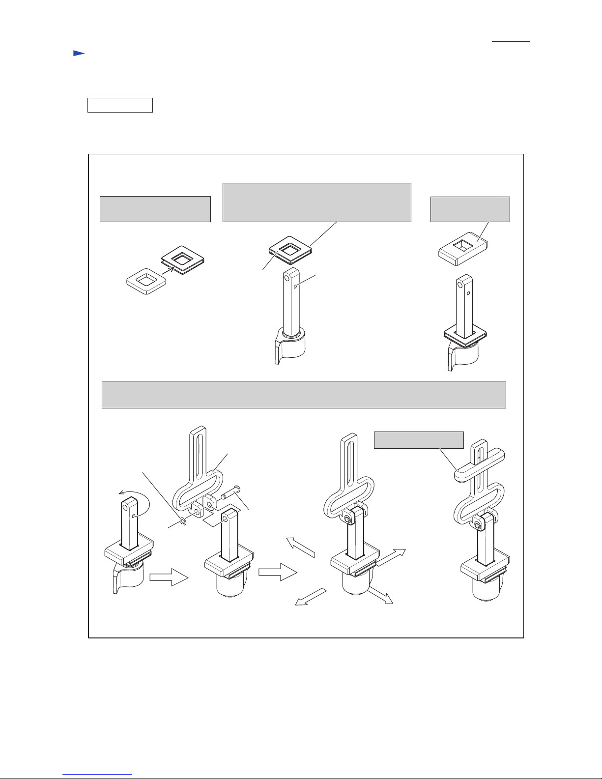
• New toolless blade clamp for quick blade changes
• Rigid aluminum support housing with blow-off device
added to protect the rod portion from saw dust for
enhanced performance against dust.
Jig saw blade No. B-10 ......... 1
Hex wrench 3 ........................ 1
Guide rule set ........................ 1 (for some countries only)
Plastic carrying case ............. 1
Optional accessories
Guide rule set
Kerf board set
Hose 28-1.5
Hose 28-3.0
Jig saw blades
Cover plate
120
110
220
230
240
6.2 650
---
380 60050/60
3.1 650 380 60050/60
3.0 650 380 60050/60
2.9 650 380 60050/60
6.5 380 60050/60
Continuous Rating (W)
Voltage (V) Cycle (Hz) Input Output Max. Output (W)
Current (A)
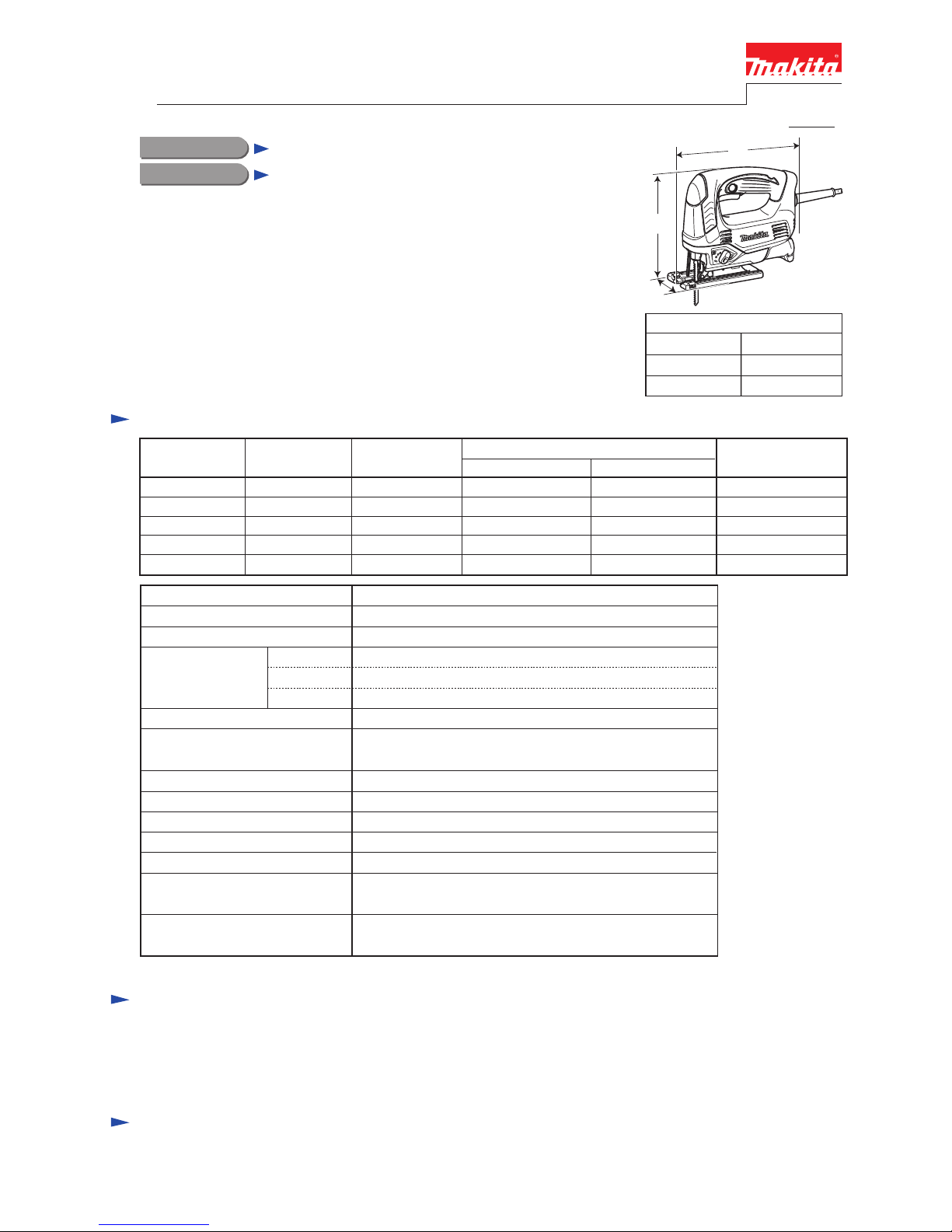
Dimensions: mm (")
Width (W)
Height (H)
Length (L) 236 (9-1/4)
77 (3)
199 (7-7/8)
L
H
W
* When cutting with optional blade No. B-16L
Weight according to
EPTA-Procedure 01/2003: kg (lbs) 2.4 (5.2)
No load speed: strokes per min.
Aluminum
Capacities: mm (")
Wood*
20 (25/32)
Steel 10 (3/8)
Stroke length: mm (") 23 (7/8)
Shank type
Protection against electric shock
Power supply cord: m (ft) Europe: 4.0 (13.1), Australia, Brazil: 2.0 (6.6),
Other countries: 2.5 (8.2)
Double insulation
Variable speed control by dial Yes
10.5
Housing type
Cut settings
Vibration measured according to
EN60745-2-11: m/s²
3 Orbital settings + Straight cutting
Yes
Material of base
Toolless blade change
500 - 3,100
B-type
90 (3-1/2)
Clamshell type
Aluminum
TECHNICAL INFORMATION