3
Important points to note before commencing Installation of your Bath shower mixer.
You should have :-
a. Checked the contents of the box and all parts are present and correct.
b Checked to ensure the minimum site operating conditions can be met.
c. The correct tools to perform a trouble free installation.
d. Considered the surrounding environment where the installation is to take place and any potential hidden
dangers.
e. Isolated both the hot and cold water supplies.
Note : If not already present , you may wish to consider installing isolation valves for ease of future maintenance.
Isolation valves can be fitted anywhere prior to connecting the Bath shower mixer to the water supply
pipes. However , they should always be installed in a safe and convenient place for ease of future access.
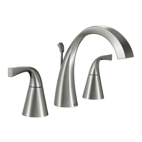
Installation
1. Ensure that both the Hot and Cold water supplies are isolated.
2. Taking the bath shower mixer, place the Plinth seal(s) (9) under the Plinth(s) (8), seat the bath shower
mixer onto the bath, whilst still ensuring that the Plinth seal(s) (9) is correctly located under the Plinth(s)(8).
Failure to do this may result in water leakage during use between the base of the bath shower
mixer and the bath.
3. Place Sealing washer(s) (10) onto the Inlet tail(s) (7) and then screw Nut(s) (11) onto the Inlet tail(s) (7),
but do not fully tighten. Correctly align the bath shower mixer to the desired position on the bath and
whilst holding the bath shower mixer, tighten Nut(s) (11) until the bath shower mixer is firmly fixed in the
correct position.
4. Your bath shower mixer should now be firmly fixed in position.
5. Connect the ‘Hot’ water supply to the ‘Hot’ inlet tail (7). (This is usually the left inlet tail when viewed from
the front) and the ‘Cold’ water supply to the ‘Cold’ inlet tail (7)
6. Check all joints are tight and the water connections have been made correctly.
7. Ensure that the shower outlet swivel connector (19) has the water outlet directed to either side of the
spout (see diagram on page 2 , position ‘ok’) . Failure to do this will lead to the shower hose obstructing
the bath fill outlet.
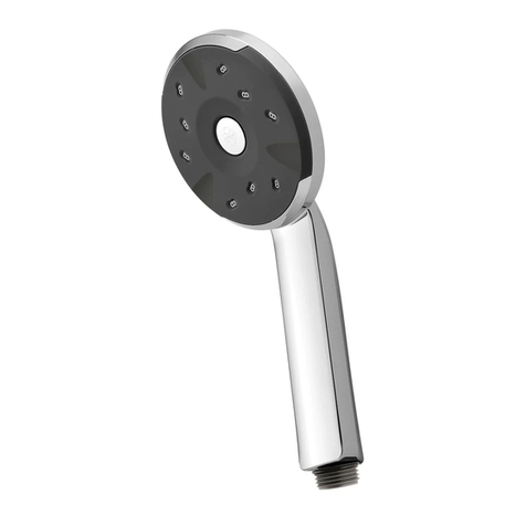
8. Connect the shower hose to the Handset and the Shower outlet swivel connector (19) at the other end.
9. Fit the shower handset into the wall mount bracket , place the wall mount bracket against the wall to find
a suitable place to fix the wall mount bracket (Note - when deciding where to fix the wall mount bracket ,
please ensure that the shower hose will not be stretched or subjected to any unnecessary tight bends).
Once a suitable place is found , mark the position of the wall mount bracket . Remove the shower handset
and fix the wall mount bracket to the wall taking care of any hidden pipes when doing so.
10. Place the handset into the wall mount bracket
11. Turn on the ‘Cold’ water supply.
12. Slowly turn on the ‘Cold’ bath tap as there may be a sudden spurt of water. Then turn the bath tap
on and off several times and ensure water flows through the tap outlet and also the tap turns off correctly
whilst continuing to check all joints for any leaks.
Please note, it is advisable to check the joints for several minutes to ensure all joints are water tight.
13. Turn off the ‘Cold’ bath tap.
14. Turn on the ‘Hot’ water supply and repeat the above process for the ‘Hot’ bath tap. Caution should be
taken when working with ‘Hot’ water to prevent scalding.
15. Now turn on both hot and cold bath taps to ensure a mixed water temperature can be achieved.
16. Take hold of the shower handset , Lift the diverter knob and check that the water now diverts to the
handset . Check all joints to ensure that there are no leaks
17. Turn off both hot and cold bath taps. Congratulations you have now successfully installed your new
KEA bath shower mixer.
Operating Conditions
Your Bath shower mixer is designed to be used in conjunction with either High or Low water pressure
systems. Your product should be fitted in compliance with the Water Authority Regulations. If you are
unsure as to what the regulations require, You can contact your Local Water Authority for further details.
Minimum operating pressure = 0.5 bar
Maximum operating pressure = 5 bar
Maximum Static Pressure = 10 bar
2
Product Dimensions
Contents
Important Note:-
The swivel outlet (19) should be
direct to either side of the bath spout
to avoid interference with the water
flow from the bath spout outlet.
Outlet position ok
Outlet position ok
Do not position
in this direction
Part Code Description
1 T10060 Cap
2 30100595 Grubscrew
3 B50130-002 Handle
4 E20137 Hot Cartridge
5 B50150-001 Bath/shower mixer Body
6 40000048 Inlet Tail Sealing Washer
7 B50130-004 Inlet Tail
8 B50130-003 Plinth
9 40000082 Plinth Seal
10 B51031-008 Sealing Washer
11 B51031-009 Nut
12 40000024
13 A12500-007
14 30100119
15 A10040-003
16 B50150-002
17 B50150-003
18 B50150-005
19 B50150-007
20 E20136 Cold Cartridge
21 B55130-003
22 B55120-002
23 B55080-006
24 B55580-015
25 B55600-008
26 B50150-004
27 B28070-016 Flow Straightener
Divertor Assembly
Shower outlet Swivel
Connector
