manuals.online logo
Brands
  1. Home
  2. •
  3. Brands
  4. •
  5. Mitel
  6. •
  7. Conference System
  8. •
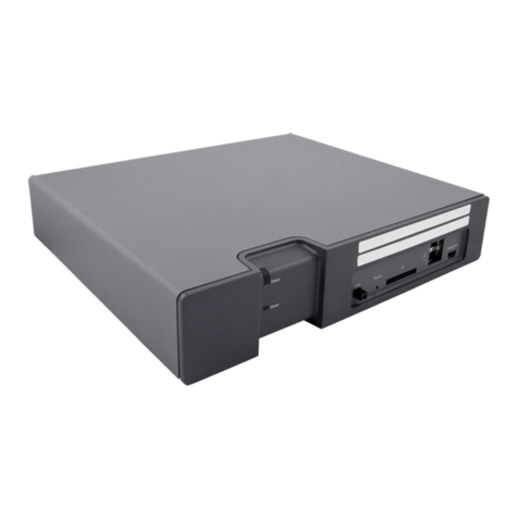
  9. Mitel Service Appliance 100 User manual

Mitel Service Appliance 100 User manual

Configuration, Status, Specifications
Quick Install Guide
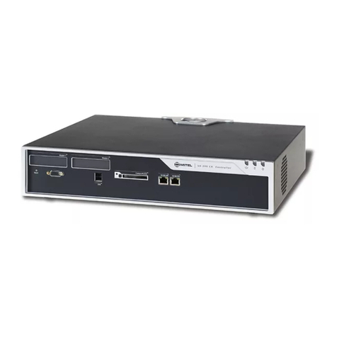
Service Appliance 100 (SA-100)
PN 800-1449-01
Network Configuration (DHCP)
Once the Service Appliance 100 is installed and powered on, by default, DHCP
network configurationisset.Formoreinformation,seethe Service Appliance 100
(SA-100) Planning, Installation and Administration Guide.
Network Configuration (Static IP) from a Console
1. Use a null-modem, DB9 female to DB9 female serial cable to connect the Service
Appliance 100 to a console PC.
2. On the PC or laptop, start a terminal emulation program and connect to the
Service Appliance 100 using these serial communication settings: 19200 bps, 8
data bits, no parity, one stop bit, no handshake.
3. At the login prompt, enter Login: root and Password: ShoreTel. The default
password should be changed upon configurationoftheappliancethrough
Director.
4. At the prompt, type: stcli to display the configuration commands.
5. Choose from the menu options and follow the on-screen instructions for setting
network parameters, including IP Address, subnet mask and gateway.
Network Indicator LEDs
Each LAN connector provides two LEDs: Link/Act (Left) and Activity (Right). LAN LED
indicators display the activity and communication speed of the connected network.
Indicator Indicator Code
Link/Activity Indicators are
off The Network Interface Card (NIC) cannot detect an
Ethernet network.
Link Indicator is green The NIC is connected to a valid network at 1000 Mbps.
Link Indicator is amber The NIC is connected to a valid network at 10/100
Mbps.
Activity indicator is
blinking green Network data is being sent or received.
Specifications
Feature Specification
Dimensions 1.67 in (4.3 cm) (H) x 17.09 in (43.4cm) (W) x 15.5
in (39.4 cm) (D).
Weight 17.8 lb (8.06 kg).
Input Voltage 100-240 VAC, 50-60 Hz, 4-2 A.
Heat Dissipation 1039 BTU/hour maximum.
Operating Temperature 10 to 35˚C with a maximum temperature gradation of
10 degrees C per hour.
Humidity 20-80% relative humidity (non-condensing) with a
maximum humidity gradation of 10% per hour.
Información de la NOM (sólo para México)
La información que se proporciona a continuación aparece en el dispositivo descrito
en este documento, en cumplimiento de los requisitos de la Norma Oficial Mexicana
(NOM):
Importador: Network1
Pico de Veracruz 435, PH,
Jardines de la Montana
14210 Mexico D.F.
Número de modelo: E10S
Voltaje de
alimentación:
100–240 V CA
Frecuencia: 50/60 Hz
Consumo eléctrico: 4–2 A
配置、状态、规格
快速安装指南
PN 800-1449-01
网络配置 (DHCP)
一旦安装 Service Appliance 100 并接通电源,默认情况下,DHCP 网络配置会设
定好。要了解更多信息,请参阅 Service Appliance 100 (SA-100) 计划、安装和管
理指南。
从控制台进行网络配置(静态 IP)
1. 使用一根零调制解调器 DB9 母接头到 DB9 母接头的串口电缆,将 Service
Appliance 100 连接到一台主控 PC。
2. 在 PC 或便携式电脑上,启动终端仿真程序,并在以下串行通信设置下连接到
Service Appliance 100 :19200 bps、8 个数据位、无奇偶校验位、一个停止
位、无同步交换。
3. 在 Mitel 登录提示窗口中输入登录名:root 和密码:Mitel。在通过
Director 进行电器配置时应修改默认密码。
4. 在提示窗口中键入:stcli 以显示配置命令。
5. 从菜单选项中做出选择,并遵照屏幕说明设置网络参数,包括 IP 地址、子网
掩码和网关。
网络 LED 指示灯
每个 LAN 接口都提供两个 LED:Link/Act(左侧)和 Activity(右侧)。LAN LED
指示相连网络的活动和通信速度。
指示灯 指示灯代码
Link/Activity 指示灯熄灭 网络接口卡 (NIC) 无法检测出 Ethernet 网络。
Link 指示灯为绿色 NIC 以 1000 Mbps 的数据传输率连接到一个有
效的网络。
Link 指示灯为琥珀色 NIC 以 10/100 Mbps 的数据传输率连接到一个
有效的网络。
Activity 指示灯为绿色并闪烁 正在发送或接收网络数据。
规格
特性 规格
尺寸 1.67 英寸 (4.3 cm) (H) x 17.09 英寸 (43.4cm) (W)
x 15.5 英寸 (39.4 cm) (D)。
重量 17.8 lb (8.06 kg)。
输入电压 100-240 VAC, 50-60 Hz, 4-2 A。
散热 最高 1039 BTU/ 小时。
工作温度 10 至 35 C(每小时温度变化不得超过 10 摄氏
度)。
湿度 20-80% 相对湿度(非冷凝)- 每小时湿度变化不得
超过 10%。
Información de la NOM (sólo para México)
La información que se proporciona a continuación aparece en el dispositivo
descrito en este documento, en cumplimiento de los requisitos de la Norma
Oficial Mexicana (NOM):
Importador: Network1
Pico de Veracruz 435, PH,
Jardines de la Montana
14210 Mexico D.F.
Número de modelo: E10S
Voltaje de
alimentación:
100–240 V CA
Frecuencia: 50/60 Hz
Consumo eléctrico: 4–2 A
Service Appliance 100 (SA-100)
Mitel Networks Corporation
350 Legget Dr.
Kanata, Ontario K2K 2W7
Canada
+1.844.937.6483
Copyright © 2017 Mitel Networks Corporation. All rights reserved.
Mitel Networks Corporation
350 Legget Dr.
Kanata, Ontario K2K 2W7
Canada
+1.844.937.6483
Copyright © 2017 Mitel Networks Corporation. All rights reserved.
简介
Service Appliance 100 简介
Service Appliance 100 是一种密封式电器,经优化后具有适应力和安全性,能够
运行 Mitel 服务。
该电器通过以下部件确保连通性:
 两个 RJ-45 局域网 (LAN) 连接器(可使用任何一个)。
 一个 DB-9(公头)、RS-232C 串行通信维护端口(19200 bps、8 个数据位、
无奇偶校验位、一个停止位、无同步交换)。
Service Appliance 100 包装内含:

Service Appliance 100

电源线

1 套机架安装套件和说明书
 快速安装指南(本指南)
 前挡板

产品信息指南
安装 连接
将 Service Appliance 100 安装到一个 19 英寸的机架中 Service
Appliance 100 只能用随机提供的机架安装套件安装到一个 19 英寸机架中。
请参阅机架安装套件内包含的安装说明。
安装场所要求
为保证 Service Appliance 100 拥有最理想的工作条件,请确认工作环境充分通
风,没有气体或尘埃颗粒,并且不受电气噪声的影响。
安装设备
安装该电器需要准备以下设备
 用于电源连接的交流浪涌电压保护器(可选)
 一 (1) 根用于连接交换机与局域网的 RJ-45 电缆
 2 号菲利普斯式改锥
接通 Service Appliance 100 的电源
将该电器连接到网络后,将其连接到交流电源,为其通电。
1. 将交流浪涌电压保护器(未提供)插入接地的交流电源。
2. 将所提供的电源线一端插入电器后部的插孔,然后将另一端插入交流浪涌电压
保护器。
3. 按下设备正面的电源指示灯 / 电源按钮。
电源指示灯按钮现在应点亮。
 如果电源指示灯 / 按钮未点亮,请确保电源线已插入电器和电源。
 如果前面板上的四个 LED(1 至 4)中有任何一个在几分钟之后依然亮着,说
明出现了内部错误。请参阅 Mitel 维护指南“诊断指示灯”部分,了解关于错
误代码的信息,或登录 http://www.shoretel.com,联系 Mitel 支持服务部。
LAN 端口会自动检测网络传输速率。网络连接建立后,网络 LED 会指示传输速率
一旦将 Service Appliance 100 固定到机架上,它就可以连
接到数据网络。
使用一条 RJ-45 以太网电缆将一个或两个 LAN 端口连接到
网络子网。
尽管两个端口都能够检测和响应链路状态,该电器一次只使用
一个 LAN 端口。
将 Service Appliance 100 连接到网络
安装 Service Appliance 100 挡板
如下图所示,将挡板连接到 Service Appliance 100。取下可选装的锁定开关,并
存放在安全位置。
维修程序
警告: Service Appliance 100 不包含任何可现场维修的零件。请将任何需要维修
的设备退回给 Mitel。
项目 指示灯、按钮或接口 说明
1 电源指示灯 / 电源按钮 当系统接通电源时,电源指示灯就会点亮。
电源按钮可控制系统的内部电源输出。当安
装了系统挡板时,电源按钮被遮挡。
2 硬盘驱动器工作指示灯 当硬盘驱动器工作时会点亮。
3 诊断指示灯 系统启动时,四个诊断指示灯会显示错误
代码。请参阅 Mitel 维护指南中的“诊断
指示灯”。
4 系统状态指示灯 系统正常工作时,指示灯为绿色。系统出现
需要引起注意的故障时,指示灯为琥珀色。
5 系统识别按钮 这些前面板和后面板按钮可用来定位一个包
含多个电器的机架内的特定系统。当按下某
个按钮时,前后指示灯均点亮,再次按按钮
时,指示灯会熄灭。
6 滑出式系统标识面板 上面包含 Mitel 产品 ID、零件号码和序列
号。下面包含两个内部 NIC 的 MAC 地址。
Service Appliance 100 前面板指示灯
项目 指示灯、按钮或接口 说明
1 串行接口 连接一个串口设备到系统上。
2 Ethernet 接口 嵌入式 10/100/1000 NIC 接口。数据传输
率和连接类型是自适应的。
3 系统状态指示灯 系统正常工作时,指示灯为绿色。系统出现
需要引起注意的故障时,指示灯为琥珀色。
4 系统识别按钮 这些前面板和后面板按钮可用来定位一个包
含多个电器的机架内的特定系统。当按下某
个按钮时,前后指示灯均点亮,再次按按钮
时,指示灯会熄灭。
5 电源 250 W 电源 AC 电缆连接。
6 固定夹具 固定电缆。
Service Appliance 100 后面板指示灯
Introduction
About The Service Appliance 100
The Service Appliance 100 is a sealed appliance, optimized for resiliency and security,
capable of running ST system services.
The appliance provides connectivity through:
• Two RJ-45 Local Area Network (LAN) connectors (either one may be used).
• One DB-9 (male), RS-232C maintenance port (19200 bps, 8 data bits, no parity,
one stop bit, no handshake) for serial communications.
The Service Appliance 100 package contains:
• Service Appliance 100
• Power cord
• 1U rack mount kit with instructions
• Quick Installation Guide (this guide)
• Front bezel
• Product information guide
Installation Connections
Installing the Service Appliance 100 in a 19-inch Rack The Service
Appliance 100 can be mounted in a 19-inch rack only by using the rack mount kit
provided.
Refer to the installation instructions included in the rack mount kit.
Installation Location Requirements
To ensure optimum operating conditions for the Service Appliance 100, verify
the operating environment is adequately ventilated, free of gas or airborne
particles, and isolated from electrical noise.
Installation Equipment
To install the appliance, you need the following equipment
• AC surge protector for the power connection (optional)
• One (1) RJ-45 cable for connecting the appliance to the local area network
• #2 Phillips screwdriver
Powering on the Service Appliance 100
After connecting the appliance to the network, power on the device by connecting it
to an AC power source.
1. Plug an AC surge protector (not provided) into a grounded AC power source.
2. Plug one end of the provided power cord into the receptacle on the back of the
appliance, then plug the other end into the AC surge protector.
3. Press the power-on indicator/power button on the front of the unit.
The power-on indicator button should now be lit.
• If the power-on indicator/button is not lit, make sure the power cord is plugged
into the appliance and the power source.
• If any of the four diagnostic LEDs on the front panel (numbered 1 to 4) remains
lit after a few minutes, there is an internal error. Refer to the “Diagnostic Lights”
section in the Maintenance Guide for information on error codes, or contact
WHFKQLFDOVXSSRUW at http://www.shoretel.com.
The LAN ports auto-sense the network transport rate. When the network connection
is established, the network LED indicates a transport rate of 100 Mbps or 1000 Mbps,
and whether there is network activity.
Once the Service Appliance 100 is secured to a rack, it can be
connected to the data network.
Use an RJ-45 Ethernet cable to connect one or both of the
LAN ports to the network subnet.
While both ports can detect and respond to link status, the appli-
ance uses only one LAN port at a time.
Connecting the Service Appliance 100 to the Network
Installing the Service Appliance 100 bezel
Connect the bezel to the Service Appliance 100 as shown in the figurebelow.
Remove and store the optional locking key in a secure location.
Servicing Procedures
WARNING: The Service Appliance 100 contains no internal fieldserviceableparts.
Return the equipment to 0LWHO for any required service procedures.
Item Indicator,
Button or
Connector
Description
1 Power-on
indicator/ power
button
The power-on indicator lights when the system
power is on.
The power button controls the internal power supply
output to the system. When the system bezel is
installed, the power button is not accessible.
2 Hard drive activity
indicator
Lights up when the hard drive is in use.
3 Diagnostic
indicator lights
The four diagnostic lights display error codes
during system startup. See “Diagnostic Lights” in
the Maintenance Guide.
4 System status
indicator
Lights blue during normal system operation. Lights
amber when the system needs attention due to a
problem.
5 System
identification
button
These front and back panel buttons can be used to
locate a particular system within a rack containing
multiple appliances. When a button is pushed, both
front and back indicators light until the button is
pushed again.
6 Slide-out system
identification panel
The top contains the product ID, part number and
serial number. The bottom contains two MAC
addresses for the two internal NICs.
Service Appliance 100 Front Panel Indicators
Item Indicator,
Button or
Connector
Description
1 Serial connector Connects a serial device to the system.
2 Ethernet connectors Embedded 10/100/1000 NIC connectors. The data
rate and connection type are auto-negotiated.
3 System status
indicator
Lights blue during normal system operation.
Lights amber when the system needs attention due
to a problem.
4 System identification
button
These front and back panel buttons can be used to
locate a particular system within a rack containing
multiple appliances. When a button is pushed,
both front and back indicators light until the
button is pushed again.
5 Power Supply 250 W power supply AC power cable connection.
6 Retention clip Secures the power cable.
Service Appliance 100 Back Panel Indicators
This manual suits for next models

1

Other Mitel Conference System manuals

Mitel ACD 2000 User manual

Mitel

Mitel ACD 2000 User manual

Mitel 6600 User manual

Mitel

Mitel 6600 User manual

Mitel MiVOICE BUSINESS User manual

Mitel

Mitel MiVOICE BUSINESS User manual

Mitel MiVOICE BUSINESS User manual

Mitel

Mitel MiVOICE BUSINESS User manual

Mitel MIVOICE OFFICE 250 Instruction Manual

Mitel

Mitel MIVOICE OFFICE 250 Instruction Manual

Mitel SX-200 ICP - 1.0 5020 User manual

Mitel

Mitel SX-200 ICP - 1.0 5020 User manual

Mitel MiVoice Business 3300 ICP User manual

Mitel

Mitel MiVoice Business 3300 ICP User manual

Mitel UC360 Instruction Manual

Mitel

Mitel UC360 Instruction Manual

Mitel MiVoice 5000 Instruction Manual

Mitel

Mitel MiVoice 5000 Instruction Manual

Mitel SX-200 EL User manual

Mitel

Mitel SX-200 EL User manual

Mitel 5750 Assembly instructions

Mitel

Mitel 5750 Assembly instructions

Mitel Navigator 3300 ICP User manual

Mitel

Mitel Navigator 3300 ICP User manual

Mitel SmarT-1 EuroRoute Installation guide

Mitel

Mitel SmarT-1 EuroRoute Installation guide

Mitel MIVOICE OFFICE 250 User manual

Mitel

Mitel MIVOICE OFFICE 250 User manual

Mitel 3300 Configuration guide

Mitel

Mitel 3300 Configuration guide

Mitel MiVoice Office 400 User manual

Mitel

Mitel MiVoice Office 400 User manual

Mitel 3300 User manual

Mitel

Mitel 3300 User manual

Mitel Inter-Tel 5000 User manual

Mitel

Mitel Inter-Tel 5000 User manual

Mitel MX-ONE User manual

Mitel

Mitel MX-ONE User manual

Mitel UC360 User manual

Mitel

Mitel UC360 User manual

Mitel UC360 User manual

Mitel

Mitel UC360 User manual

Mitel SX-200 User manual

Mitel

Mitel SX-200 User manual

Mitel SX-200 Operator's manual

Mitel

Mitel SX-200 Operator's manual

Mitel 5760 VC User manual

Mitel

Mitel 5760 VC User manual

Popular Conference System manuals by other brands

HME Wireless 6400 manual

HME

HME Wireless 6400 manual

Cisco EX90 user guide

Cisco

Cisco EX90 user guide

Yealink W70B DECT user manual

Yealink

Yealink W70B DECT user manual

Trust ViCtor II user manual

Trust

Trust ViCtor II user manual

Sony Ipels PCS-G50 Brochure & specs

Sony

Sony Ipels PCS-G50 Brochure & specs

Eaton SmartWire-DT manual

Eaton

Eaton SmartWire-DT manual

SystemBase C530ip-s user manual

SystemBase

SystemBase C530ip-s user manual

Polycom G7500 Administrator's guide

Polycom

Polycom G7500 Administrator's guide

TANDBERG 150 MXP Administrator's guide

TANDBERG

TANDBERG 150 MXP Administrator's guide

Siemens HiPath BizIP Operation manual

Siemens

Siemens HiPath BizIP Operation manual

TANDBERG Maestro MXP user manual

TANDBERG

TANDBERG Maestro MXP user manual

Kramer KIA-TCB Quick setup guide

Kramer

Kramer KIA-TCB Quick setup guide

The COM COM-DB90 owner's manual

The COM

The COM COM-DB90 owner's manual

Lenovo ThinkSmart Hub quick start guide

Lenovo

Lenovo ThinkSmart Hub quick start guide

ABB H82001-W product manual

ABB

ABB H82001-W product manual

Vertex Standard VX-P820 Series operating manual

Vertex Standard

Vertex Standard VX-P820 Series operating manual

rauland Telecenter IV DESCRIPTION AND GENERAL INFORMATION

rauland

rauland Telecenter IV DESCRIPTION AND GENERAL INFORMATION

Crestron UC-BX30-Z-WM quick start

Crestron

Crestron UC-BX30-Z-WM quick start

manuals.online logo
manuals.online logoBrands
  • About & Mission
  • Contact us
  • Privacy Policy
  • Terms and Conditions

Copyright 2025 Manuals.Online. All Rights Reserved.