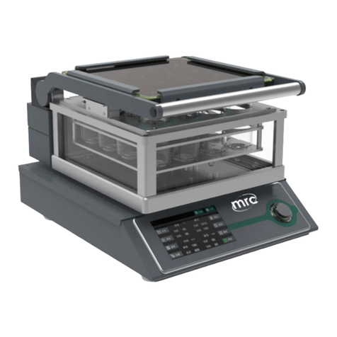
MRC SPC-60 User manual

6/8inch spin coaters
SPC-60/80
Operating instruction
PLEASE READ THIS MANUAL CAREFULLY BEFORE OPERATION
MRC.8 .22

content
1. Overview.................................................................................................................................1
2. Technical Parameters ..............................................................................................................2
3. Equipment composition ..........................................................................................................3
4. Device connection...................................................................................................................4
4.1. Installation location:.................................................................................................4
4.2. Vacuum unit ................................................................................................................4
4.3. Circuit installation.......................................................................................................4
4.4. Loading substrate:.......................................................................................................5
4.5. Substrate alignment.....................................................................................................5
5. Experiment operation..............................................................................................................6
5.1. Whole process:............................................................................................................6
5.2. Operation interface: ....................................................................................................6
6. Matters needing attention........................................................................................................8
6.1. Equipment cleaning ....................................................................................................8
6.2. Tray replacement.........................................................................................................8

1
1. Overview
The spin coater uses the centrifugal coating principle to coat liquid or colloidal materials on silicon,
crystal, quartz, ceramics and other substrates to form thin films. This process has a wide range of
applications in the field of materials research. The working chamber of the spin coater is made of
PMMA, which has the advantages of beautiful, light and easy to observe.
Product features:
1. It can be used for coating organic compounds with uniform glue for film preparation.
2. It can store the process parameters of different substrates. Each coating process can be set with
different rotation speed.
3. The working chamber is made of plexiglass, which can monitor the whole process of coating.

2
2. Technical Parameters
Model
SPC-60/80
Maximum speed
10,000 RPM
Speed resolution
1 RPM
Maximum rotation time
3,000 S
Rotation time resolution
1 S
Maximum acceleration
8,000RPM/S
Size
290mm(W)x360mm(D)x370mm(H)
Weight
20kg
Power input
200-230V, single phase, 600W
Vacuum input
requirements
0.06-0.09Mpa, vacuum flow minimum 15L/min or more
Vacuum interface
φ6/8mm quick screw interface
Working gas
Non-corrosive gases such as nitrogen, argon, oxygen, etc.

3
3. Equipment composition
The overall structure:
1.Chamber upper
cover
2.Loading tray
3.Chamber bottom
cover
4.Touch screen
5.Power switch
6.USB
interface
7.Vacuum interface
8.Vacuum pump communication
port
9.Power cord
The structure of the tray is shown in the figure:
a.Central exhaust
b.O-ring
c.Vacuum adsorption tank
d.Loading tray

4
4. Device connection
4.1. Installation location:
The installation location should be selected on a flat, stable, spacious and well-ventilated surface.
Otherwise, the spinning coating effect may be affected. If you need to deal with glue containing
volatile or toxic solvents, be sure to place the equipment in a well-ventilated fume hood. The
installation location of the equipment should be away from direct sunlight or cold/heat sources and
moisture. Do not install the device on the edge of the workbench to prevent the device from slipping
off due to vibration during operation. 20cm should be delineated around the equipment as a
dangerous work area.
4.2. Vacuum unit
The vacuum gas circuit adopts the φ8mm quick screw joint, which needs to be used with the outer
diameter of 8mm hose. The installation of quick screw joint is shown in the following figure:
1) Remove the nut and pass the hose through the nut;
2) Put the hose into the joint in front of the thread, paying
attention to the need to completely cover the joint with the hose;
3) Tighten the thread, the nut can compress the hose after
tightening, and play a sealing role.
4.3. Circuit installation
First, connect the power cord of the diaphragm pump to the vacuum pump control line interface on
the back of the spin coater. The male and female ports of the interface have white dots to indicate the
position of the gap. During installation, the white dots should be aligned first, and then the male port
should be inserted tightly, and the outer nut should be tightened to connect the control line tightly.
Finally, insert the power cord into the power port on the back of the spin coater, and then connect the
plug to the socket (AC220V 50Hz) to ensure that the socket is reliably grounded.

5
4.4. Loading substrate:
Place the substrate to be processed in the center of the tray. The substrate can be wafers, glass slides,
small fragments, and other substrates suitable for spinning coating.
Notice:
The substrate must be larger than and completely cover the surface of the tray. If the selected
substrate is smaller than the loading tray, it will cause the glue to flow into the vacuum
pipeline of the equipment, thereby blocking or corroding the internal pipeline of the
equipment.
4.5. Substrate alignment
Align the center of the substrate with the center of the tray. You can turn on the vacuum pump to
adsorb the substrate on the tray plate, try to manually flip the tray plate, and observe whether the
sample rotates eccentrically. If there is eccentricity, it should be adjusted again until the substrate
alignment is completed.
Notice:
The substrate must be placed in the center of the tray. Otherwise, during high-speed rotation,
there may be flying pieces, causing damage to personnel and equipment.

6
5. Experiment operation
5.1. Whole process:
1. Connect the power supply and vacuum pump according to the instructions
2. Install the sample according to the above;
3. Press the power button to enter the operation interface, first set a low-speed (less than 1000rpm)
coating program.
4. Use a low speed and low acceleration test run first to ensure that the vacuum adsorption is firm
during operation, and observe whether the sample can be accurately aligned
5. After the trial run, wait for the running to stop, and then set the coating program as required
6. Drop the experimental liquid into the center of the sample and close the lid
7. Click “Start ”on the touch screen and wait until the coating is finished
8. After the loading tray completely stops rotating, turn off the power, remove the upper cover, and
take out the sample
5.2. Operation interface:
Boot interface
Click to enter the main interface as follows

7
The upper left part of the main interface displays the running time, the current actual value of the
stage speed and the programmed value;
The upper right part shows the current plan and the specific section of the plan;
The lower part of the main interface displays the current program information, including the speed
and duration of each segment;
The three boxes at the bottom, start and stop can control the operation and stop of the equipment,
and the setting can enter the setting interface. The pump switch can control the start and stop of the
vacuum pump.
Setting interface:
The setting interface is shown in the figure, which can store A~E five spin coating formulations.
Each formula can be set with five stages of operation. The rotation speed, acceleration and duration
of each section can be directly set by clicking the corresponding display position.
After setting the required formula, you can click the lower right corner to return to the main
interface.
Click the language switch in the lower left corner to switch between Chinese and English.

8
6. Matters needing attention
6.1. Equipment cleaning
After the equipment is used daily, a small amount of solvent should be used to clean the inner
chamber.When cleaning the vacuum tray, turn off the vacuum source first, and clean the surface of
the tray with a paper towel or soft cloth. Do not use solvents or cleaning agents to clean the tray
when it is installed.If a special solvent is needed to clean the loading tray, pull the loading tray out of
the shaft, and use a paper towel or soft cloth dipped in an appropriate amount of cleaning agent to
remove the residue on the surface of the loading tray. Do not scratch the surface to prevent damage
to the contact surface between the substrate and the tray plate.
Notice:It is strictly forbidden to use spray cleaning solvent or directly use solvent to clean
the tray plate still installed on the shaft, which may cause damage to the vacuum pump or the
spin coater.
6.2. Tray replacement
Various sizes of trays are designed to provide a flat, hard surface, suitable for processing substrates
of various sizes, weights and shapes. Here are the steps to replace the tray:
1) Turn off the external vacuum source.
2) First pull out the load tray vertically from the shaft. If the load tray is stuck, try to pull it out by
shaking it left and right.
3) Align the locating pin on the shaft with the notch on the new tray and press down vertically
4) Make sure that the load plate is pressed on the shaft without clearance.
Notch
Locating pin
Tray
Shaft
This manual suits for next models
1
Table of contents
Other MRC Laboratory Equipment manuals
Popular Laboratory Equipment manuals by other brands

German pool
German pool DSR-310BK user manual

B+K precision
B+K precision 1823a instruction manual

3D Histech
3D Histech TMA Grand Master 3.2 user guide

Thermo Forma
Thermo Forma 3911 Operating and maintenance manual

B+K precision
B+K precision 8600 Series Programming manual

J.P. SELECTA
J.P. SELECTA PLAC-CENTER manual