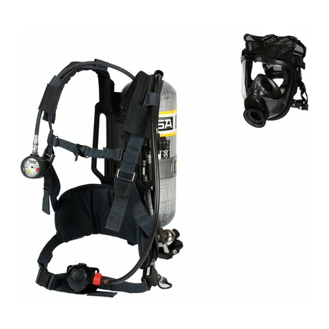
MSA G1 SCBA User manual

US
MSAsafety.com
Operating Manual
G1
SCBA
NIOSH CBRN and NFPA 1981/1982
Order No.: 10158406/01

©MSA 2014. All rights reserved.
The warranties made by MSA with respect to the product are voided if the product is not installed,
used and serviced in accordance with the instructionsin this manual. Pleaseprotect yourself and your
employees by following the instructions.
Please read and observe the WARNINGS and CAUTIONS inside. For any additional information rela-
tive to use or repair, call 1-800-MSA-2222 during regular working hours.
For alternate languages, please refer to part number 10162890.
WARNING
Read this manual carefully before using the device. The device will perform as designed only if it is
used and maintained in accordance with the manufacturer's instructions. Otherwise, it could fail to
perform as designed and persons who rely on this device for their safety could sustain serious
personal injury or death.
1000 Cranberry Woods Drive
Cranberry Township, PA 16066
USA
Phone 1-800-MSA-2222
Fax 1-800-967-0398
For your local MSA contacts please go to our website www.MSAsafety.com

3
Contents
G1
US
Contents
1 Safety Regulations ....................................................................................................................6
1.1 NIOSH Approval Information ............................................................................................................. 6
1.2 NIOSH CBRN Approval Information .................................................................................................. 7
1.3 NFPA Approval Information ............................................................................................................... 8
1.4 FCC Approval .................................................................................................................................... 8
1.5 Intrinsic Safety Approval Information ................................................................................................. 9
1.6 Industry Canada statement ............................................................................................................... 9
1.7 Important Notice for Respirator Users and Respiratory Protection Program Administrators ............. 9
1.8 Reference .......................................................................................................................................... 9
1.9 Contact Information ......................................................................................................................... 10
2 Description ............................................................................................................................... 11
2.1 G1 Facepiece .................................................................................................................................. 12
2.2 G1 Regulator (also known as Demand Valve) ............................................................................... 13
2.3 G1 Heads-Up Display (HUD) ........................................................................................................... 13
2.4 Cylinder and Valve Assembly .......................................................................................................... 14
2.5 G1 Pressure Reducer with Primary Low Pressure Warning Device ................................................ 14
2.6 G1 PASS Device ............................................................................................................................. 15
2.7 G1 Harness and Carrier Assembly .................................................................................................. 17
2.8 G1 Speaker Module (Optional) ........................................................................................................ 18
2.9 Optional Components ...................................................................................................................... 18
3 Size Selection ........................................................................................................................... 19
3.1 Respirator Fit Test ........................................................................................................................... 20
4 Visual Inspections ................................................................................................................... 21
4.1 Facepiece ........................................................................................................................................ 22
4.2 Regulator ........................................................................................................................................ 22
4.3 Pressure Reducer ............................................................................................................................ 22
4.4 Cylinder and Valve Assembly .......................................................................................................... 23
4.5 Carrier Assembly ............................................................................................................................. 23
4.6 Control Module ................................................................................................................................ 24
4.7 Power Module .................................................................................................................................. 24
4.8 Battery Module ................................................................................................................................ 24
4.9 ExtendAire II .................................................................................................................................... 25
4.10 Record Keeping ............................................................................................................................... 25

4
Contents
G1
US
5 Functional Tests ...................................................................................................................... 26
5.1 Check that the Regulator and Facepiece Can Hold a Negative Pressure ....................................... 26
5.2 Check Function of Regulator ........................................................................................................... 26
5.3 Check Function of the Control Module, Power Module, HUD
and Primary Low Pressure Warning Device..................................................................................... 27
5.4 Speaker Module Function ................................................................................................................ 29
6 Donning .................................................................................................................................... 30
6.1 Approval Verification ........................................................................................................................ 30
6.2 Preparation ...................................................................................................................................... 31
6.3 SCBA Donning Procedure ............................................................................................................... 32
6.4 Facepiece Donning Procedure ........................................................................................................ 36
7 During Use ................................................................................................................................ 41
7.1 Cold Weather Operation .................................................................................................................. 43
8 G1 Heads-Up Display (HUD) ................................................................................................... 44
8.1 G1 HUD Pressure Status ................................................................................................................ 44
8.2 G1 HUD Alarm Status ..................................................................................................................... 46
9 Control Module ........................................................................................................................ 48
9.1 PASS Device Functionality .............................................................................................................. 48
9.2 Alarms ............................................................................................................................................. 51
9.3 Secondary Alarm Icons ................................................................................................................... 54
9.4 ID Tagging ....................................................................................................................................... 56
9.5 Screen Displays During Tagging ..................................................................................................... 58
9.6 Button Functions .............................................................................................................................. 58
9.7 Turning OFF the Control Module ..................................................................................................... 59
10 After Use ................................................................................................................................... 60
10.1 Removing the SCBA ........................................................................................................................ 60
10.2 Removing the Facepiece ................................................................................................................. 63
11 Cleaning and Disinfection ....................................................................................................... 64
11.1 Cleaning and Disinfection Facepiece .............................................................................................. 65

5
Contents
G1
US
12 Cylinders .................................................................................................................................. 67
12.1 Safety Precautions for MSA Self-Contained Breathing Apparatus Cylinders .................................. 67
12.2 Preparing Cylinder for Use .............................................................................................................. 69
12.3 Installing Quick Connect Adapter to Cylinder .................................................................................. 71
12.4 Changing the Cylinder ..................................................................................................................... 72
12.5 Charging Cylinders .......................................................................................................................... 73
13 UAC Fitting ............................................................................................................................... 74
13.1 Precautions ...................................................................................................................................... 74
13.2 Filling Instructions ............................................................................................................................ 75
13.3 Transfilling between SCBAs ............................................................................................................ 76
13.4 Leakage ........................................................................................................................................... 77
14 G1 ExtendAire II EBSS ............................................................................................................ 78
14.1 Instructions for EBSS Use ............................................................................................................... 79
14.2 Inspection Before EBSS Use ........................................................................................................... 79
15 Flow Test and Overhaul Requirements ................................................................................. 82
16 Personnel ID Tag ..................................................................................................................... 83
17 Spectacle Kit ............................................................................................................................ 84
18 Telemetry Module .................................................................................................................... 86
18.1 Using the SCBA with Telemetry Module ......................................................................................... 89
19 Maintenance ............................................................................................................................. 90
19.1 Batteries .......................................................................................................................................... 90
19.2 Maintenance Instructions ................................................................................................................. 93
20 Safekeeping and Storage ........................................................................................................ 94
20.1 Storage ............................................................................................................................................ 94
20.2 Facepiece ........................................................................................................................................ 94
21 Product Labels ......................................................................................................................... 95
22 MSA G1 SCBA Limited Warranty ........................................................................................... 98

6
Safety Regulations
G1
US
1 Safety Regulations
This SCBA complies with the National Institute for Occupational Safety and Healthy (NIOSH) regula-
tion under 42 CFR Part 84 for open circuit self-contained breathing apparatus, the National Fire
Protection Association (NFPA) Standard 1981 on Open-Circuit Self-Contained Breathing Apparatus
(SCBA) for Emergency Services and the NFPA Standard 1982 on Personal Alert Safety Systems
(PASS).
1.1 NIOSH Approval Information
This pressure-demand, self-contained breathing apparatus (SCBA) is certified by the National Insti-
tute for Occupational Safety and Health (NIOSH) for use in atmospheres immediately dangerous to
life or health (IDLH):
“Immediately dangerous to life or health” means conditions that pose an immediate threat to life or
health or conditions that pose immediate threat of severe exposure to contaminants, such as radio-
active materials, which are likely to have adverse cumulative or delayed effects on health
[Title 42 CFR, Part 84.2, (Q)].
Certifying Agency Contact Information
National Institute for Occupational Safety and Health (NIOSH)
Phone: 800-CDC-4636
NIOSH Cautions and Limitations
NIOSH S - Special or Critical User’s Instructions
-Approved for use at temperatures above -25°F (- 32°C).
-Approvedonlywhenthecompressed-aircylinderis fullychargedwithair meetingtherequirements
of the Compressed Gas Association Specification G-7 for quality verification level (grade) D air or
equivalent specifications.
-Infireservice applications,MSArecommendsbreathingairqualityinaccordancewithNFPA 1989.
The cylinder shall meet applicable DOT specifications.
-Do not alter this SCBA. Altering will void the Intrinsic Safety rating and may affect the Intrinsic
Safety of the device. Misuse or abuse of the heads-up display (HUD), control module, power
module or speaker module or using this equipment in a manner or situation not intended by the
manufacturer, may result in damage to the HUD, control, power, or speaker module, may result in
personal injury or death to user or persons dependent on the user. Always inspect the HUD,
control, power, and speaker module for damage before use. If damage is found, immediately
remove the device from service. The HUD, control, power, and speaker module are approved
WARNING
Read and follow all NIOSH approval limitations. Misuse can result in serious injury or death.
J- Failure to properly use and maintain this product could result in injury or death.
M- All approved respirators shall be selected,fitted, used and maintained in accordance with MSHA,
OSHA and other applicable regulations.
N- Never substitute, modify, add or omit parts. Use only exact replacement parts in the configuration
as specified by the manufacturer.
O- Referto UsersInstructions,and/or maintenancemanualsforinformation onuseand maintenance
of these respirators.
S- Special or critical User’s Instructions and/or specific use limitations apply. Refer to user instruc-
tions before donning.

7
Safety Regulations
G1
US
intrinsically-safe and conform to UL 913 6th edition, Class I, Division 1, Groups C and D, Temper-
ature Rating T1..
-Use the SCBA with adequate skin protection when worn in gases and vapors that poison by skin
absorption (for example: hydrocyanic-acid gas).
-Approval for use against CBRN chemical warfare agents is maintained only when using approved
components and following instructions listed on the NIOSH approval matrix
(P/N 10158405).
-For non-CBRN applications see Approval Insert (P/N 10154623).
-Do not mark the SCBA, i.e., with stamps, labels, paint, or othermethod. Use of such markings may
interfere with apparatus use or may constitute a flammability hazard.
Cautions And Limitations Of Emergency Breathing Support Systems (EBSS)
-Activation or engagement of EBSS in either the donor or receiver mode changes the SCBA use to
Escape-Only, approved service time for either the donor, or the receiver is no longer applicable.
-EBSS may not be engaged or activated in donor mode after the donor End-of-Service-Time-Indi-
cator (EOSTI) has activated.
-Users must be fully trained in the operation of EBSS in accordance with a training program
conforming to the requirements of NFPA Standards 1404, Fire Service Respiratory Protection
Training and 1500, Fire Department Occupational Safety and Health Program.
-Simultaneous connection of more than two users, one donor and one receiver, is not permitted.
SCBAs operated in EBSS mode are approved for escape only.
-Entry approval only restored after re-charge, either host or donor.
-Connection not to be established after donor/host EOSTI activation.
-Limited to one donor/receiver (host/parasite) pair. Not suitable for connection in CBRN environ-
ment.
1.2 NIOSH CBRN Approval Information
This SCBA has been designated by NIOSH as being CBRN (chemical, biological, radiological, and
nuclear) Agent Approved. It complies with the special tests under NIOSH 42 CFR 84.63(c); Chemical
Agent Permeation and Penetration Resistance Against Distilled Sulfur Mustard (HD) and Sarin (GB)
and the Laboratory Respirator Protection Level (LRPL) tests.
DANGER
Use in conjunction with personal protective ensembles that provide appropriate levels of protection
against dermal hazards.
Some CBRN agents may not present immediate effects from exposure, but can result in delayed
impairment, illness, or death.
Direct contact with CBRN agents requires proper handlingof the SCBA after each use and between
multiple entries during the same use. Decontamination and disposal procedures must be followed.
If contaminated with liquid chemical warfare agents, dispose of the SCBA after decontamination.
The respirator should not be used beyond 6 hours after initial exposure to chemical warfare agents
to avoid possibility of agent permeation.
FAILURE TO FOLLOW THE ABOVE ITEMS IN ADDITION TO ALL ESTABLISHED CBRN
PROTECTIVE MEASURES CAN RESULT IN SERIOUS PERSONAL INJURY OR DEATH.

8
Safety Regulations
G1
US
NIOSH Cautions and Limitations of Use for CBRN
(Chemical, Biological, Radiological, and Nuclear) SCBA
1.3 NFPA Approval Information
The MSA G1 SCBA meets the requirements of the National Fire Protection Association (NFPA) 1981
(2013 edition) Standard on Open-Circuit Self-Contained Breathing Apparatus (SCBA) for Emergency
Services when configured in accordance with the NFPA approval. When the SCBA is equipped with
a power and control module, the SCBA meets the requirements of the NFPA 1982 (2013 edition)
Standard on Personal Alert Safety Systems (PASS) when configured in accordance with the NFPA
approval. The MSA G1 SCBA must be used in accordance with NFPA 1500 Standard on Fire Depart-
ment Occupational Safety and Health Program to maintain NFPA 1981.
The certification agency for NFPA compliant SCBA used by MSA is Safety Equipment Institute (SEI).
SEI can be contacted for clarification on your NFPA compliant version of this SCBA or to report any
operational malfunction.
Safety Equipment Institute (SEI)
Certifying Agency Contact Information
1307 Dolley Madison Blvd.
Suite 3A
McLean, VA 22101
Phone (703) 442-5732
Fax (703) 442-5756
1.4 FCC Approval
This device complies with Part 15 of the FCC Rules. Operation is subject to the following conditions:
(1) This device may not cause harmful interference and
(2) This device must accept any interference that may cause undesired operation.
NOTE: The G1 HUD, control, power, or speaker module have been tested and found to comply with
the limits for a Class B digital device, pursuant to Part 15 of the FCC Rules.These limits are designed
to provide reasonable protection against harmful interference in a residential installation. This equip-
ment generates, uses, and can radiate radio frequency and, if not installed in accordance with instruc-
tions, may cause harmful interference to radio communications.
Q- Use in conjunction with personal protective ensembles that provide levels of protection against
dermal hazards.
R- Some CBRN agents may not present immediate effects from exposure, but can result in delayed
impairment, illness, or death.
T-
Direct contact with CBRN agents requires proper handling of the SCBA after each use and
between multiple entriesduring the sameuse. Decontamination and disposal procedures must be
followed. If contaminated with liquid chemical warfare agents, dispose of the SCBA after decon-
tamination.
U- Therespiratorshouldnotbe usedbeyond6hoursafterinitial exposuretochemicalwarfareagents
to avoid possibility of agent permeation.
NOTICE
Changes or modifications not expressly approved by MSA could void the user's authority to
operate the equipment.

9
Safety Regulations
G1
US
1.5 Intrinsic Safety Approval Information
The MSA G1 SCBA equipped with a mask mounted G1 Regulator with HUD, battery, power, speaker
and control module are intrinsically-safe and conform to UL 913 6th edition, Class I, Division 1,
Groups C and D, Temperature Rating T1.
Do not alter this SCBA. Altering will void the Intrinsic Safety rating and may affect the Intrinsic Safety
of the device. Misuse or abuse of the heads-up display (HUD), control module, power module or
speaker module or using this equipment in a manner or situation not intended by the manufacturer,
may result in damage to the HUD, control, power, or speaker module, may result in personal injury or
death to user or persons dependent on the user. Always inspect the HUD, control, power, or speaker
module for damage before use. If damage is found, immediately remove the device from service. Use
only batteries specified within this manual to stay compliant with the instrinsic safety approval.
1.6 Industry Canada statement
Thisdevicecomplieswith RSS-210oftheIndustry CanadaRules.Operation issubjecttothe following
two conditions: (1) This device may not cause harmful interference, and (2) this device must accept
any interference received, including interference that may cause undesired operation.
Ce dispositif est conforme à la norme CNR-210 d'Industrie Canada applicable aux appareils radio
exempts de licence. Son fonctionnement est sujet aux deux conditions suivantes: (1) le dispositif ne
doit pas produire de brouillage préjudiciable, et (2) ce dispositif doit accepter tout brouillage reçu, y
compris un brouillage susceptible de provoquer un fonctionnement indésirable.
1.7 Important Notice for Respirator Users and Respiratory Protection Program Administrators
(1) An adequate respiratory protection program mustinclude knowledge of hazards, hazard assess-
ment, selection of proper respiratory protective equipment, instruction and training in the use of
equipment, inspection and maintenance of equipment, and medical surveillance.
[See OSHA regulations, Title 29 CFR, Part 1910.134 (c).]
(2) This SCBA may be used only after proper instruction and training in its use as specified in NFPA-
1500 and OSHA regulations Title 29 CFR, Part 1910.134.
1.8 Reference
Formore informationon theSCBA useandperformancestandards,consult the followingpublications:
-NFPA Standard1500, FireDepartment OccupationalSafetyandHealth Programs (Chapter 5) and
NFPA 1981 Standard, on Open-Circuit SCBA’s for Fire Service. Above publications are available
from the following: National Fire Protection Association, Batterymarch Park, Quincy, MA 22269.
-ANSI Standard Z88.5, Practices for Respiratory Protection for the Fire Service; and, ANSI
Standard Z88.2, Practices for Respiratory Protection. American National Standards Institute,
1430 Broadway, New York, NY 10018.
-OSHA Safety and Health Standards (29 CFR 1910) (see specifically Part 1910. 134), available
fromtheSuperintendentofDocuments,U.S. GovernmentPrintingOffice, Washington,DC 20402.
Compressed Gas Association, Inc., 1725 Jefferson Davis Hwy., Suite 1004, Arlington, VA 22202.
10
Safety Regulations
G1
US
1.9 Contact Information
In the event of a product concern, contact your local MSA authorized repair center or distributor, who
will provide the necessary information to MSA for issue resolution. To report any serious concerns or
to inquire about the products use the following contact information:
MSA North America
Corporate Center MSA Canada MSA de Mexico, S A De C V
1000 Cranberry Woods Drive
Cranberry Township, PA 16066
Phone 1-800-MSA-2222
Fax 1-800-967-0398
16435 118th Avenue
Edmonton AB T5V 1H2
Phone 1-800-MSA-2222
Fax 1-800-967-0398
Fraccionamiento Industrial Avenida
Del Conde #6
76240 El Marques, Queretaro
Phone 01 800 672 7222
Fax +52-44 2227 3943

11
Description
G1
US
2 Description
The MSA G1 - referred to hereafter as SCBA - is a pressure-demand self-contained breathing appa-
ratus (SCBA) operating independent of the ambient air for use in atmospheres immediately
dangerous to life or health.
Breathable air is supplied to the user from a compressed air cylinder via a pressure reducer, a regu-
lator and a facepiece. The exhalation air is released directly into the ambient atmosphere.
The integrated personal alert safety system (PASS) provides the user with the ability to monitor move-
ment through a motion sensor. When a user remains motionless for 30 seconds, the PASS device
goes into full alarm to alert those around the user. The PASS device also monitors cylinder pressure
and battery status.
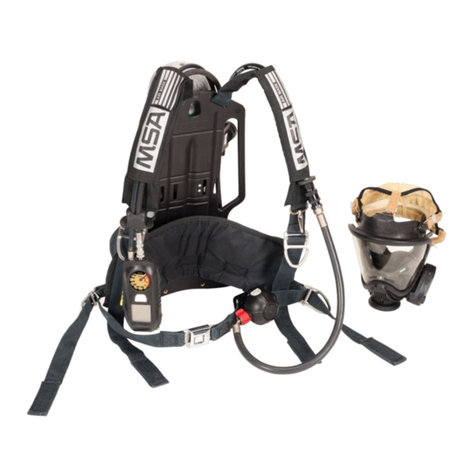
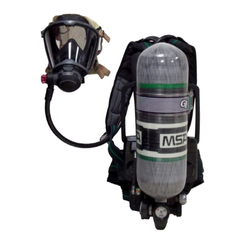
The G1 SCBA consists of the following components:
-G1 Facepiece
-G1 Regulator (also referred to as Demand Valve)
-G1 Heads-Up Display (HUD) (part of both facepiece and regulator)
-G1 Pressure Reducer with low pressure warning device
-G1 Control Module
-G1 Power Module
-Cylinder and Valve Assembly
-G1 Carrier and Harness Assembly
Optional components:
-G1 Speaker Module
-ExtendAire II
-Quick-Fill Pouch
-Telemetry Module

12
Description
G1
US
2.1 G1 Facepiece
The facepiece provides breathable air from the regulator past an inhalation valve to the inside of the
lens (to minimize lens fogging) and then through the check valves into the nosecup. Exhaled air is
directed out of the exhalation valve by the nosecup directly to ambient air. The face seal provides a
snug, comfortable fit, and tight seal. The facepiece is available in 3 sizes (small, medium, large) and
the nosecup is available in 3 sizes (small, medium, large).
The facepiece is equipped with a mechanical speech diaphragm that enhances speech communica-
tion. The HUD is provided inside the facepiece through light pipes from the regulator.
When in safe atmospheres with no regulator attached, ambient air can be inhaled directly through an
opening to facilitate breathing and speaking with minimal resistance.
Facepiece Versions
The facepiece is available with different head harnesses; fabric (both SpeeD-ONand 5-point) or
rubber (5-point).

13
Description
G1
US
2.2 G1 Regulator (also known as Demand Valve)
The mask mounted G1 Regulator is a pressure-demand regulator, which maintains a positive pres-
sure in the facepiece while the SCBA is in use. The positive pressure regulator reduces the pressure
coming from the pressure reducer further to provide breathable air to the user.
The regulator is connected to the facepiece with a fixed position Push-To-Connect (PTC) connection.
The regulator has two cover options available, purge and solid cover. The purge cover allows users
to activate the regulator manually or provide a quick burst of air during use without using the bypass
knob.
The regulator houses an electronic module which provides HUD functionality and microphone place-
ment. The microphones are activated when the regulator is connected to the facepiece and the user
begins breathing. Inhalation noise is not amplified by the system.
The hose for the regulator is available in two options, continuous or quick connect. The continuous
hose provides an uninterrupted connection from the pressure reducer to the regulator. A quick
connect coupling is positioned on the chest between the pressure reducer and regulator to enable
regulatorremovalfrom theSCBA for testingorrepair. Bothtypes ofhoses forelectronicversions have
integrated wiring and hoses.
2.3 G1 Heads-Up Display (HUD)
The HUD is integrated into the regulator and projects light into the facepiece. The HUD allows users
to see the cylinder pressure and alarm status while wearing the SCBA. The HUD receives the infor-
mation on the SCBA and power from the power module. The HUD consists of 7 LEDs which are sepa-
rated on the left and right sides to improve visibility and clarity. A light sensor in the regulator varies
the LED intensity depending on the ambient light condition (optional setting).

14
Description
G1
US
2.4 Cylinder and Valve Assembly
The cylinder and valve assembly store high pressure air which will be reduced to provide the user
breathable air. Cylinders are available in multiple pressures and rated service times. The valve
assembly provides the user the ability to open the pressure to the rest of the system. The valve
assembly consist of a handwheel for opening and closing the valve, pressure gauge that always
provides the pressure in the cylinder, threaded CGA connection for filling and attachment, and burst
disc for over pressurization.
The SCBA can be attached to the cylinder in multiple configurations. A threaded or quick connection
is available and a threaded cylinder can easily be upgraded to a quick connect attachment. The
cylinder can be connected to the SCBA by a side connection off the cylinder valve (remote connect).
When using a remote connect cylinder, a dove tail interlocking feature is used to secure the cylinder
to the backplate of the SCBA.
Cylinder Capacity
* As approved by NIOSH
2.5 G1 Pressure Reducer with Primary Low Pressure Warning Device
The pressure reducer reduces the cylinder pressure to an intermediate pressure, which is in turn
further reduced by the regulator to a pressure that is respirable by the user. The pressure reducer
incorporates a fail safe design which ensures air flow to the user in the event of a malfunction within
the pressure reducer.
The pressure reducer incorporates an intermediate pressure relief valve, and a cylinder connector
with a sintered filter to capture particulates that may be in the air stream.
Universal Air Connection (UAC)
All NFPA approved SCBA are equipped with a UAC fitting (Universal Rescue Connection). The UAC
fitting is a male fitting inlet for use by Rapid Intervention Teams for emergency filling of the SCBA or
during transfill operations.
Connection Type Connection Location
Threaded Remote (side)
Quick Connect Remote (side)
Capacity (Cubic Ft.) Pressure (psig) Rated Svc* Life (Min.)
45 2216 30
45 4500 30
66 4500 45
88 4500 60

15
Description
G1
US
Primary Low Pressure Warning Device (Bell)
The primary low pressure warning device alarms when there is approximately 35 % of the SCBA’s
rated service time remaining and when the cylinder valve is first opened, providing an audible indica-
tion that the alarm is working properly. NIOSH regulation states that the primary low pressure warning
device must alert the user at 35% 2%. MSA sets all low pressure warning signals to the mean of
the requirement, hence 35 %.
NOTE: The remaining service time calculations are based on a 40 LPM (liters per minute) NIOSH
breathing rate.
2.6 G1 PASS Device
The PASS device on the G1 SCBA is made up of three components: battery module, power module,
and control module. The PASS device provides the user the ability to monitor movement through a
motion sensor. When a user remains motionless for 30 seconds, the PASS device goes into full alarm
to alert those around the user. The PASS device also monitors cylinder pressure and battery status.
G1 Control Module
The G1 control module is the user’s interface with the SCBA and PASS device.
The control module is assembled to the high pressure air source and to the power module by a pneu-
matics and electronic hose assembly. It is equipped with an analog gauge as well as a graphical
display to provide vital information: numeric cylinder pressure, battery status, alarms and time
remaining (optional).
Cylinder Remaining Service Time
(Approx.) End of Service Time Indicator Pressure
(Approx.)
30 min. 2216 psi 10 minutes 775 psi
30 min. 4500 psi 10 minutes 1575 psi
45 min. 4500 psi 16 minutes 1575 psi
60 min. 4500 psi 21 minutes 1575 psi

16
Description
G1
US
When the control module is being read by the user, no buddy lights on the control module will flash
and a white gauge light will illuminate, to enable the user to read the gauge and display. If the SCBA
is equipped with the optional telemetry module, the radio link status and evacuation alarms are
displayed. The integrated PASS motion sensor is housed within the control module. The ALARM
button of the control module activates the full PASS alarm with or without air pressure.
G1 Power Module
The power module serves as the power supply and provides all of the information for the control
module, regulator and speaker module.
The power module is connected to the backplate. It connects to the battery module, emits audible
PASS alarms and pre-alarms and has 4 buddy lights.
The battery module is equipped with six C-cell batteries. The system notifies the user when the
batteries need to be replaced by emitting an audible tone from the power module, displaying an empty
battery icon on the display of the control module, and by a flashing yellow LED on the HUD.
The power module is also equipped with a RIT light, which activates when low pressure alarm (config-
urable to medium pressure alarm) occurs, to make it easier to see the UAC in the dark.
The power module has a data logging feature that records information about the SCBA while the
control module is turned on. This data log memory can be accessed using the MSA A2 Software.
The power module contains an internal real time clock. This clock can be reset using the
MSA A2 Software. By default, the internal clock is set to Eastern Standard Time.
CAUTION
Before placing the SCBA in service, verify that the internal clock is set to the appropriate time as per
the user's geographic location. Failure to do so can result in inaccurate data logging.

17
Description
G1
US
2.7 G1 Harness and Carrier Assembly
The harness and carrier assembly consists of:
-Backplate (houses the power module, battery module, and pressure reducer)
-Cylinder band with latch to hold the cylinder
-Shoulder pads
-Adjustable pull straps
-Lumbar pad
-Waist belt
-Regulator Keeper
-Chest strap (optional)
Shoulder Straps
The shoulder pads are available in two options; standard and serviceable. The standard shoulder
pads provide weight distribution across the shoulder, friction pad to prevent slippage of the straps,
increased visibility with retroreflection material, and steel buckles for a secure fit. The serviceable
shoulder pads provide the same features as the standard shoulder pad but allow the user to easily
access the hoses without having to disconnect them from the SCBA. The tunnels on these pads are
released using snap buttons to ease in swapping or repair of components. The inside and outside of
the shoulder straps are identifiable by print/stitching. A facepiece clip can also be attached to either
shoulder strap.
The control module, regulator, and speaker module can be positioned either on the left or right
shoulder pad. Typically the regulator and speaker module are placed on the left shoulder and the
controlmodule isplaced onthe rightshoulder.The regulatorkeepercan bepositioned inmultiple loca-
tions including the waist belt and chest strap.The regulator and the regulator keeper must be on the
same side of the user.
Lumbar Pad
The lumbar pad is available in three versions:
-Adjustable Lumbar Pad - The adjustable lumbar pad provides the user three positions for ideal
comfort. The lumbar pad can be adjusted by one-hand and can be adjusted while worn. The
lumbar pad also has a swivel feature to allow it to move with the user.
-Fixed Position Lumbar Pad - The fixed position lumbar pad provides the user with the middle posi-
tion of the adjustable lumbar pad position and is not adjustable. The lumbar pad also has a swivel
feature to allow it to move with the user.
-Basic Lumbar Pad - The basic lumbar pad is a fixed position, non-swivel unit that provides a low
profile, light weight lumbar option for the user.

18
Description
G1
US
2.8 G1 Speaker Module (Optional)
The speaker module amplifies andclarifies the speech from the facepiece duringuse. When inhaling,
the breathing sound will not be amplified (optional). The speaker module is turned OFF when the
complete SCBA is turned OFF and can also be activated/deactivated with its button. Pressing of the
button is acknowledged by a beep.
2.9 Optional Components
ExtendAire II
he ExtendAire II is a pneumatic manifold that allows two users to connect and share intermediate
pressure air. Each manifold contains both a male and female Quick Connect for ease of connection.
The manifold is attached to three feet of usable hose. A pouch is attached to the user’s left side to
store and protect the manifold and hose assembly.
Quick-Fill Pouch
The Quick-Fill Pouch is a storage pouch attached to the user’s right side. It is similar to the ExtendAire
II pouch, but is used to hold a Quick-Fill line. The pouch is held securely closed by a combination of
hook and loop fasteners and snaps, but can be opened using one hand.
Telemetry Module
The telemetry module provides the firefighter with two-way communication with Incident Command.
The firefighter's vital statistics such as cylinder pressure, approximate service time remaining, PASS
alarm, low battery alarm, and thermal alarm are transmitted back to Incident Command. Also, the fire-
fighter has the ability to be evacuated remotely by Incident Command. The radio transmitter is located
inside of the power module. The telemetry module is only available for SCBAs with integrated PASS
devices. For details see Chapter 18.

19
Size Selection
G1
US
3 Size Selection
Regardless of facial dimensions and respirator sizing charts, an actual respirator fit test, either quali-
tative or quantitative must be performed to ensure the correct respirator size selection.
(1) Fit test the respirator size relative to your facial features and dimensions. The safety adminis-
trator or program manager might assist in selecting the initial size to try.
(2) Carefully don the mask and conduct a negative pressure seal test. See donning instructions for
procedure.
(3) Ifthe facepiecedoes notpass thenegative pressureseal testor feelsuncomfortable, trythe next
nearest size relative to your face.
Passing the negative pressure seal test does not verify the size is correct. The size selected must be
verified by successfully passing a Respirator Fit Test, either qualitative or quantitative. If the respirator
passes a negative pressure seal test but DOES NOT pass a Respirator Fit Test, try the next nearest
size.
Once the proper size is selected, the respirator must pass a negative pressure seal test every time
the facepiece is donned to ensure proper fit before using the respirator.
If other than facial seal leakage is detected, the condition must be investigated and corrected before
another test is made.
The facepiece must also pass the negative pressure sealtest before the user attempts to enter a toxic
atmosphere.
The facepiece will not furnish protection unless all inhaled air is drawn through the SCBA.

20
Size Selection
G1
US
3.1 Respirator Fit Test
A qualitative or quantitative respirator fit test must be carried out routinely for each wearer of this respi-
rator to determine or confirm the amount of protection that the respirator provides.
Quantitative Test
If a quantitative fit test is used, a fit factor of at least 500, based on ambient aerosol fit test methods
or equivalent, is required before any type of respirator is assigned to an individual.
Qualitative Test
If a qualitative fit test is used, only validated protocolsare acceptable. The individual must pass a test
designed to assess a fit factor of at least 500.
NOTE: When this facepiece is used for CBRN APR, a fit factor of at least 2000 is required for quan-
titative or qualitative test. Refer to User Instructions (P/N 10158743) for more information regarding
CBRN APR use.
Use Quik Chek Kit (P/N 805078) to perform fit testing and following instructions provided with the kit.
The fit test kit includes an adapter and instructions. Canister sold separately. Be sure the probe does
not contact the face during fit testing. Failure to do so can result in false protection factor readings.
WARNING
The user must perform a respirator fit test (Quantitative Test or Qualitative Test) and follow all warn-
ings and limitations specified. Failure to do so can result in serious personal injury or death.
Other manuals for G1 SCBA
9
Table of contents
Other MSA Respiratory Product manuals

MSA
MSA FIREHAWK M7 ULTRA ELITE 10084690 Setup guide

MSA
MSA advantage 1000 User manual

MSA
MSA G1 Industrial SCBA User manual

MSA
MSA Abrasi-Blast Series User manual

MSA
MSA PremAire System User manual

MSA
MSA Versa-Hood User manual

MSA
MSA 3S small User manual

MSA
MSA alpha Series User manual

MSA
MSA G1 APR User manual

MSA
MSA Duo-Flo User manual

MSA
MSA 3S-H User manual

MSA
MSA OptimAir MM 2K User manual

MSA
MSA PremAire Combination User manual

MSA
MSA AirHawk MMR User manual

MSA
MSA AirHawk II User manual

MSA
MSA SSR 90 User manual

MSA
MSA SavOxCap 60 User manual

MSA
MSA Advantage 3100 User manual

MSA
MSA OptimAir 6A User manual

MSA
MSA FireHawk M7 I-HUD User manual