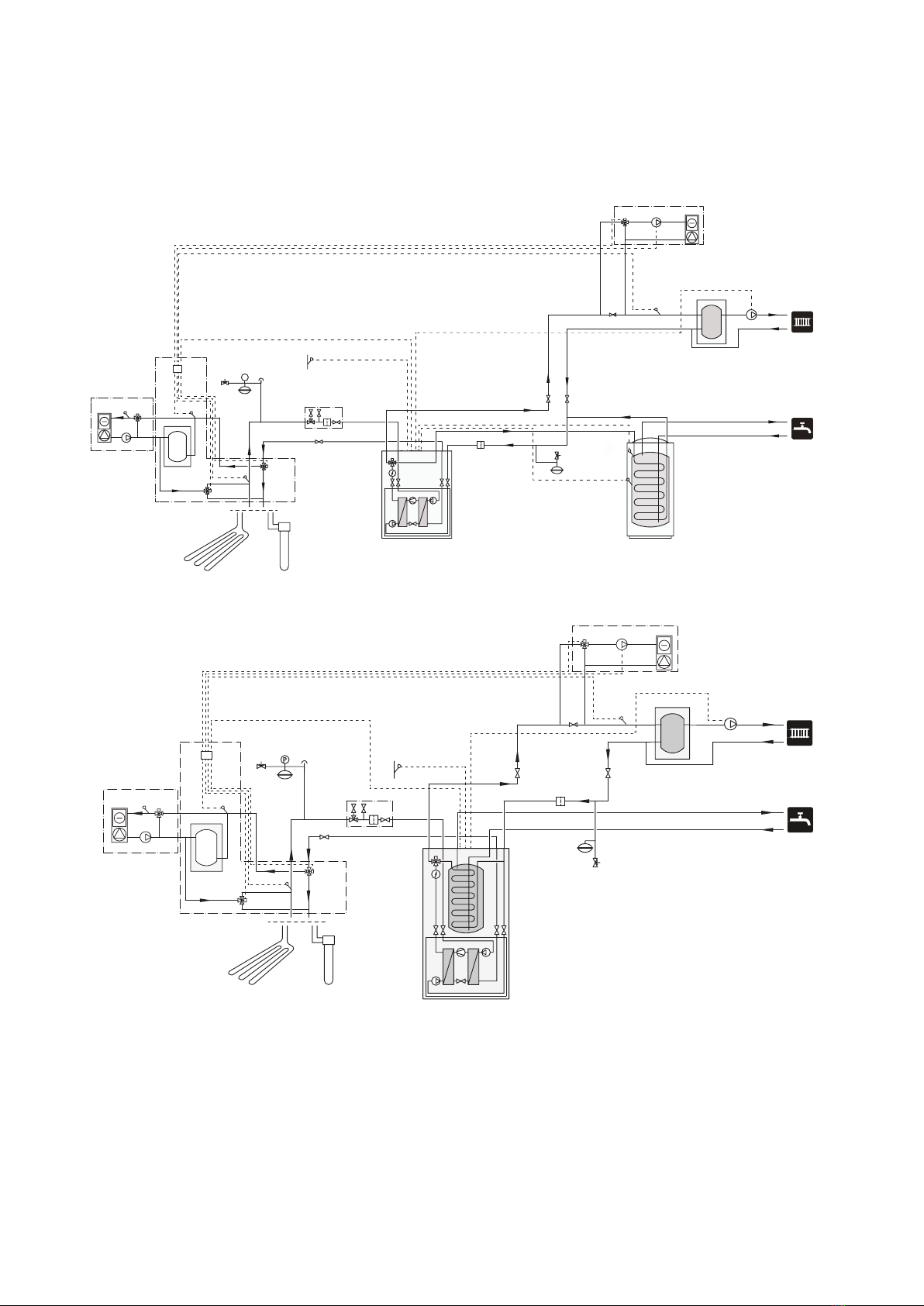
Nibe ACS 45 User guide

LEK
ACS 45
SE
Installatörshandbok Passiv/aktiv kyla (4-rör)
GB
Installer manual Passive/active cooling (4 pipe)
DE
Installateurhandbuch Passiver/aktiver
Vierrohrkühlung
IHB 1710-3
431285


Svenska
Viktig information
OBS!
Denna symbol betyder fara för människa eller
maskin.
TÄNK PÅ!
Vid denna symbol finns viktig information om
vad du ska tänka på när du sköter din anlägg-
ning.
Allmänt
ACS 45 är ett tillbehör som möjliggör för din värmepump
att styra produktion av värme och kyla oberoende av
varandra.
Utöver detta tillbehör (beroende på systemlösning) kan
växelventil för kyla, cirkulationspump, shuntventil samt
distributionssystem för kyla behövas.
Kylsystemet tillförs kyla från köldbärarkretsen med hjälp
av en cirkulationspump via en shuntventil.
Passiv kyla görs utan att kompressorn är i drift, medan i
aktiv kyla är kompressorn i drift.
För att anläggningen ska fungera krävs fritt flöde för
värmebäraren till exempel med hjälp av volymkärl för
kyla.
Driftläge kyla aktiveras av temperaturen på utgivaren
och eventuell rumsgivare, rumsenhet eller separat
rumsgivare för kyla (om exempelvis två olika rum ska
kylas respektive värmas samtidigt).
Vid kylbehov aktiveras växelventilen kyla och köldbärar-
cirkulationspumpen. Shunten reglerar efter kylgivaren
och ett kylbörvärde som bestäms av vald kylkurva.
Gradminuter beräknas efter värdet på den externa
temperaturgivaren för köldbärare ut och kylbörvärdet.
Gradminut-värdet avgör enligt menyinställningar i vilket
kyldriftläge anläggningen befinner sig i.
TÄNK PÅ!
Detta tillbehör kan kräva en uppdatering av
programvaran i din värmepump.
Lägsta programvaruversion på mjukvaran i vär-
mepumpen som krävs är 4150R7 eller högre.
Kompatibla produkter
■F1255
■F1345
■F1355
■F1145
■F1155
■F1245
Innehåll
Buntband4 st
Värmeledningspasta3 st
Isoleringstejp1 st
Apparatlåda med tillbehörskort1 st
Aluminiumtejp3 st
Temperaturgivare3 st
Komponentplacering apparatlåda (AA25)
LEK
AA5-X4
AA5-S2
AA5-X2 AA5-X9 X1
FA1
AA5-F1AA5
AA7
AA7-X2
Elkomponenter
Automatsäkring, 10AFA1
Anslutningsplint, spänningsmatningX1
TillbehörskortAA5
Anslutningsplint, givare och extern blocke-
ring
AA5-X2
Anslutningsplint, kommunikationAA5-X4
Anslutningsplint, cirkulationspump, shunt
och hjälprelä
AA5-X9
DIP-switchAA5-S2
Finsäkring, T4AH250VAA5-F1
Extra reläkortAA7
Anslutningsplint, shunt- och växelventilAA7-X2
Beteckningar i komponentplacering enligt standard IEC
81346.
Röranslutning
Allmänt
För att undvika kondensbildning måste rörledningar och
övriga kalla ytor isoleras med diffusionstätt material. Vid
stort kylbehov krävs fläktkonvektor med droppskål och
avloppsanslutning.
Köldbärarkretsen ska förses med tryckexpansionskärl.
Eventuellt befintligt nivåkärl byts ut.
3ACS 45 | SE

Backventil
Montera en backventil (RM22) mellan två T-rörsanslut-
ningarna till shuntventilen för värmedump (se prin-
cipschema).
Shuntventil, kyldump
Shuntventilen (QN18) placeras i köldbärarsystemet via
T-rörsanslutningar enligt principschema.
AB
A
B
■Anslut köldbärare ut från värmepumpen
efter växelventil (QN12) via T-rör till port A
på shuntventilen (öppnar vid ökasignal).
■Anslut returledningen från kylsystemet till
gemensam port AB på shuntventilen (alltid
öppen).
■Anslut köldbärare in till värmepumpen från kollektorn
via T-rör till port B på shuntventilen (stänger vid mins-
kasignal).
Shuntventil, värmedump
Shuntventilen (QN36) placeras i klimatsystemet på
framledningen från värmepumpen via T-rörsanslutningar
enligt principschema.
A
B
AB
■Anslut framledningen till cirkulations-
pump, värmedump (GP20) och fläktkon-
vektorn till gemensam port AB på
shuntventilen (alltid öppen).
■Anslut framledningen till klimatsystmet
till port A på shuntventilen (öppnar vid ökasignal).
■Anslut returledningen från fläktkonvektorn till fram-
ledningen till klimatsystemet via T-rör till port B på
shuntventilen (stänger vid minskasignal).
Växelventil, kyla/värme
Växelventilen (QN12) placeras i köldbärarsystemet på
framledningen från värmepumpen enligt principschema.
A
B
AB
■Anslut framledningen till kylsystemet till port
A på växelventilen (öppen vid signal).
■Anslut köldbärare ut från värmepumpen till
gemensam port AB på växelventilen (alltid
öppen).
■Anslut köldbärare ut till kollektorn till port B
på växelventilen (normalt öppen, motor i viloläge).
Cirkulationspump, värmedump
Montera cirkulationspumpen (GP20) efter shuntventilen
för värmedump (QN36) på framledningen till fläktkon-
vektorn.
Volymkärl
Montera volymkärlet (CP21) för kyla på mellan växelventil
(QN12), shuntventil (QN18) och kylsystemet.
Temperaturgivare
■Temperaturgivare (BT57) monteras på returen till vär-
mepumpen i kollektorn efter t-rörsanslutning från
kylsystemreturen via shuntventil (QN18).
■Temperaturgivare (BT64) monteras på framledning till
kylsystemet vid t-rörsanslutning till volymkärl (CP21).
■Temperaturgivare (BT75) monteras på framledningen
till klimatsystemet efter värmedumpen.
LEK
LEK
E
Temperaturgivarna monteras med buntband tillsammans
med värmeledningspasta och aluminiumtejp. Därefter
ska de isoleras med medföljande isolertejp.
OBS!
Givar- och kommunikationskablar får ej förläg-
gas i närheten av starkströmsledning.
ACS 45 | SE4

Principschemor
OBS!
Dessa är principscheman.
Verklig anläggning ska projekteras enligt gällan-
de normer.
Förklaring
Extern tillsatsEB1
Extern eltillsatsEB1
Säkerhetsventil, värmebärarsidaFL10
Avstängningsventil, värmebärarsidaQM42 - QM43
TrimventilRN11
Värmepumpsystem (Master)EB100
Temperaturgivare, uteBT1
Temperaturgivare, varmvattenladdningBT6
Temperaturgivare, värmebärare fram, Ex-
tern
BT25
Temperaturgivare, värmebärare retur, Ex-
tern
BT71
VärmepumpEB100
Kylmodul AEP14
Kylmodul BEP15
Säkerhetsventil, köldbärarsidaFL10 - FL11
Säkerhetsventil, värmebärarsidaFL12 - FL13
SmutsfilterHQ12 - HQ15
Filterkulventil (smutsfilter)QZ2 - QZ5
Avstängningsventil, köldbärarsidaQM50 - QM53
Avstängningsventil, värmebärarsidaQM54 - QM57
Växelventil, värme/varmvattenQN10
BackventilRM10 - RM13
KylsystemEP25
Temperaturgivare, framledningBT2
FläktkonvektorEP25
CirkulationspumpGP20
ShuntventilQN25
Passiv/aktiv kyla 4-rörEQ1
Apparatlåda med tillbehörskort (ACS 45)AA25
Temperaturgivare, kollektorBT57
Temperaturgivare, framledning kylaBT64
Temperaturgivare, framledning efter vär-
medump
BT75
Volymkärl, kylaCP21
FläktkonvektorEP24
Cirkulationspump, värmedumpGP20
Växelventil, kyla/värmeQN12
Shuntventil, kyldumpQN18
Shuntventil, värmedumpQN36
BackventilRM22
Övrigt
Manometer, köldbärarsidaBP6
Temperaturgivare, varmvatten framBT7
Ackumulatortank med varmvattenslingaCP10
Utjämningskärl (UKV)CP20
Expansionskärl slutet, värmebärarsidaCM1
Expansionskärl slutet, köldbärarsidaCM3
Kollektor, köldbärarsidaEP12
Säkerhetsventil, värmebärarsidaFL2
Säkerhetsventil, köldbärareFL3
Cirkulationspump, värmebärare externGP10
Avluftningsventil, köldbärarsidaQM21
Avstängningsventil, värmebärare framQM31
Avstängningsventil, värmebärare returQM32
Avstängningsventil, köldbärare framQM33
Avstängningsventil, köldbärare returQM34
Anslutning, påfyllning köldbärareXL27 - XL28
Beteckningar enligt standard IEC 81346-1 och 81346-2.
5ACS 45 | SE

Principschema F1145/F1155 med ACS 45 och passiv/aktiv kyla (4-rör)
-QM31 -QM32
-EB100-HQ1
-QM34
-XL15
-EB100
-BT1
-EB100 -FL2
-CM1
-CM2
P
-BP6
-FL4 -QM21
P
-CP21
-BT57
-BT64
-QN25
-EP25-BT2
-AA25
-EQ1
-EQ1
-RM22
-EP24
-QN36 -GP20
-BT75
-EQ1
-EQ1
-QN18
-QN12
-EP25
-GP20
-GP10
-CP10
-BT7
-EB100
-BT6
-CP20
-EP12
Principschema F1245/F1255 med ACS 45 och passiv/aktiv kyla (4-rör)
-EP25
-EP25 -BT2 -QN25
-GP20
-EQ1
-BT64
-AA25
-CP21
-BP6
-FL4 -QM21
-CM2
-EQ1
-RM22
-EP24
-GP20
-EQ1
-CM1
-FL2
-EQ1
-BT75
-BT57
-QN18
-QN12
-EP12
-QN36
-CP20
-GP10
-QM34
-HQ1
-QM31 -QM32
-EB100
-XL15
-BT1
ACS 45 | SE6

Principschema F1345 med ACS 45 och passiv/aktiv kyla (4-rör)
Principschema F1355 med ACS 45 och passiv/aktiv kyla (4-rör)
-QZ3
-QZ2
-QZ5
-QZ4
7ACS 45 | SE

Elinkoppling
OBS!
All elektrisk inkoppling ska ske av behörig
elektriker.
Elektrisk installation och ledningsdragning ska
utföras enligt gällande bestämmelser.
Värmepumpen ska vara spänningslös vid instal-
lation av ACS 45.
Elkopplingsversioner F1345
F1345 har olika elinkopplingar beroende på när värme-
pumpen tillverkades. För att se vilken elinkoppling som
gäller för din F1345, kontrollera om beteckningen "2.0"
syns ovanför plintarnas högra sida enligt bild.
LEK
Elschema finns i slutet av denna installatörshandbok.
Anslutning av kommunikation
Om flera tillbehör ska anslutas eller redan finns installe-
rade måste de efterföljande korten anslutas i serie med
föregående kort.
Använd kabeltyp LiYY, EKKX eller likvärdig.
Detta tillbehör innehåller ett tillbehörskort (AA5) som
ska anslutas direkt till värmepumpen på ingångskortet
(plint AA3-X4) i F1145/F1155/F1245/F1255, på plint X6
i F1345 utan elkopplingsversion 2.0 eller på plint AA101-
X10 i F1345 med elkopplingsversion 2.0 eller F1355.
1
2
3
4
5
6
7
8
AA5-X4
15
A
B
GND
A
B
GND
A
B
GND
A
B
GND
A
B
GND
14
13
AA3-X4
1
2
3
4
5
6
7
8
AA5-X4
X6
1 2 3 4
A
B
GND
1
2
3
4
5
6
7
8
15
14
13
1
2
3
4
5
6
7
8
F1145/F1155
AA3-X4
ON
12345678
-X9
-X2
24 20212223 1516171819 1011121314 56789 1
1
N
L
PE
PE
1
2
3
4
5
6
7
8
2
3
4
5
6
7
8
9
234
-X8
-X4
-X10
-X1
AA5-X4
ON
12345678
-X9
-X2
24 20212223 1516171819 1011121314 56789 1
1
N
L
PE
PE
1
2
3
4
5
6
7
8
2
3
4
5
6
7
8
9
234
-X8
-X4
-X10
-X1
AA5-X4
F1345 utan 2.0
Tillbehörskort 1
Tillbehörskort 2
EB100
X6
F1245/F1255
AA3-X4
345
-X10
-AA101
67
A
B
GND
F1345 med 2.0/F1355
AA101-X10
Anslutning av matning
Anslut spänningsmatningen till plint X1 enligt bild.
3
2
1
4
N
230V 50Hz-X1
L
PE
Apparatlåda Externt
ACS 45 | SE8

Översikt tillbehörskort
-X2
1
12 34 56
23456
-X1
AA7-X2
ON
12345678
-X9
-X2
24 20212223 1516171819 1011121314 56789 1
1
N
L
PE
PE
1
2
3
4
5
6
7
8
2
3
4
5
6
7
8
9
234
-X8
-X4
-X10
-X1
AA5-X2 AA5-X9
AA5-X10
Anslutning av givare och extern justering
Använd kabeltyp LiYY, EKKX eller likvärdig.
Temperaturgivare, kollektor (BT57)
Anslut temperaturgivaren till AA5-X2:23-24.
Temperaturgivare, framledning kyla (BT64)
Anslut temperaturgivaren till AA5-X2:19-20.
Temperaturgivare, framledning efter värmedump
(BT75)
Anslut temperaturgivaren till AA5-X2:21-22.
Temperaturgivare, kyla/värme (rumsgivare för kyla,
BT74)
En extra temperaturgivare (rumsgivare för kyla) kan
kopplas till värmepumpen för att bättre kunna avgöra
när det är dags att byta mellan kyl- och värmedrift.
För inkoppling av BT74 se respektive produkts IHB.
Använd en 2-ledare med minst 0,5 mm² kabelarea.
Extern blockering, passiv kyla (valfritt)
En kontakt (NO) kan anslutas till AA5-X2:13-14 för att
kunna blockera passiv kyla. När kontakten sluts blockeras
passiv kyla.
Extern blockering, aktiv kyla (valfritt)
En kontakt (NO) kan anslutas till AA5-X2:15-16 för att
kunna blockera aktiv kyla. När kontakten sluts blockeras
aktiv kyla.
24 20212223 1516171819 1314
AA5-X2
Externt
Apparatlåda
Extern blockering
B A
A: Passiv kyla
B: Aktiv kyla
BT75 BT64BT57
TÄNK PÅ!
Reläutgångarna på tillbehörskortet får max be-
lastas med 2 A (230 V) totalt.
9ACS 45 | SE

Anslutning av cirkulationspump, värmedump
(GP20)
Anslut cirkulationspumpen (GP20) till AA5-X9:8 (230 V),
AA5-X9:7 (N) och jord (PE).
1
2
3
4
5
6
7
8
9
L
N
PE
Apparatlåda Externt
GP20
AA5-X9
Anslutning av växelventilmotor (QN12)
Anslut växelventilmotorn (QN12) till AA5-X9:2 (manöver),
AA5-X9:1 (N) och X1:4 (L).
1
2
3
4
3
2
1
4
Apparatlåda Externt
AA5-X9
X1
QN12
Manöver
L
N
Anslutning av shuntmotor (QN18)
Anslut shuntmotorn (QN18) till AA5-X9:6 (230 V, öppna),
AA5-X9:5 (N) och AA5-X9:4 (230 V, stäng).
1
2
3
4
5
6
7
8
9
QN18
Apparatlåda Externt
AA5-X9
Öppna
Stäng
N
SH -
SH +
Anslutning av shuntmotor (QN36)
Anslut shuntmotorn (QN36) till AA7-X2:4 (230 V, öppna),
AA5-X10:1 (N) och AA7-X2:2 (230 V, stäng).
1 2 3 4 5 6
1
2
Apparatlåda Externt
AA7-X2
AA5-X10
QN36
Öppna
Stäng
N
SH -
SH +
DIP-switch
DIP-switchen (S2) på tillbehörskortet (AA5) ska ställas in
enligt nedan.
ON
12345678
ON
12345678
-X9
-X2
24 20212223 1516171819 1011121314 56789 1
1
N
L
PE
PE
1
2
3
4
5
6
7
8
2
3
4
5
6
7
8
9
234
-X8
-X4
-X10
-X1
AA5-S2
Reläutgång för kyllägesindikering
Möjlighet finns till extern kyllägesindikering genom relä-
funktion via ett potentialfritt växlande relä (max 2 A) på
kopplingsplint X5.
Ansluts kyllägesindikering till kopplingsplint X5 måste
det väljas i meny 5.4.
ACS 45 | SE10

Programinställningar
Programinställningen av ACS 45 kan göras via startgui-
den eller direkt i menysystemet.
Startguiden
Startguiden visas vid första uppstart efter värmepumps-
installationen, men finns även i meny 5.7.
Menysystemet
Om du inte gör alla inställningar via startguiden eller
behöver ändra någon inställning kan du göra detta i
menysystemet.
Meny 5.2.4 - tillbehör
Aktivering/avaktivering av tillbehör.
Välj: "passiv/aktiv kyla 4-rör".
Meny 1.1 - temperatur
Inställning av inomhustemperatur (kräver rumstempera-
turgivare).
Meny 1.9.5 - kylinställningar
Här kan du exempelvis göra följande inställningar:
■Lägsta framledningstemperatur vid kyla.
■Önskad framledningstemperatur vid utomhustempe-
raturen +20 och +40 °C.
■Tid mellan kyla och värmedrift och tvärt om.
■Val om rumsgivare ska styra kylan.
■Hur mycket rumstemperaturen får sjunka respektive
öka jämfört med önskad temperatur innan övergång
till värme respektive kyldrift (kräver rumsgivare).
■Gradminutnivåer för kyla.
■Diverse shuntinställningar.
Meny 4.9.2 - autolägesinställning
Om värmepumpens driftläge är satt till "auto" väljer den
själv, beroende på medelutetemperatur, när start och
stopp av tillsats samt värmeproduktion respektive kyldrift
ska tillåtas.
I denna meny väljer du dessa medelutetemperaturer.
Du kan även ställa in under hur lång tid (filtreringstid)
medeltemperaturen räknas. Väljer du 0 innebär det att
aktuell utetemperatur används.
Meny 5.6 - tvångsstyrning
Tvångsstyrning av de olika komponenterna i värmepum-
pen samt i de olika tillbehören som eventuellt är anslut-
na.
EQ1-AA5-K1: Signal till växelventil (QN12).
EQ1-AA5-K2: Signal (stäng) till shunt (QN18).
EQ1-AA5-K3: Signal (öppna) till shunt (QN18).
EQ1-AA5-K4: Aktivering av cirkulationspump (GP20).
EQ1-AA7-K1: Signal (stäng) till shunt (QN36).
EQ1-AA7-K2: Signal (öppna) till shunt (QN36).
TÄNK PÅ!
Se även Installatörshandboken för produkten
som ACS 45 ska anslutas till.
Tekniska uppgifter
Tekniska data
ACS 45
230V ~ 50HzMärkspänning
250x100x175(mm)Mått (BxDxH)
067 195Art nr
624 67 96RSK nr
11ACS 45 | SE

English
Important information
NOTE
This symbol indicates danger to person or ma-
chine .
Caution
This symbol indicates important information
about what you should observe when maintain-
ing your installation.
General
ACS 45 is an accessory that makes it possible for your
heat pump to control the production of heating and
cooling independently of each other.
In addition to this accessory (depending on system
solution) a reversing valve for cooling, circulation pump,
mixing valve and distribution system for cooling may be
necessary.
The cooling system supplies cooling from the collector
circuit using a circulation pump via a mixing valve.
Passive cooling occurs without the compressor running,
while active cooling occurs when the compressor is run-
ning.
For the installation to work, the heating medium must
flow freely, for example using a volume vessel for cooling.
Operating mode cooling is activated by the temperature
of the outdoor sensor and any room temperature
sensors, room units or separate room sensors for cooling
(if two different rooms are to be heated respectively
cooled at the same time for example.)
When cooling is required the cooling reversing valve and
the brine circulation pump are activated. The mixing
valve regulates according to the cooling sensor and a
cooling set point value that is determined by the selected
cooling curve. Degree minutes are calculated in response
to the value on the brine out external temperature sensor
and the cooling set point value. The degree minute value
determines in which cooling mode the installation is ac-
cording to the menu settings.
Caution
This accessory may require a program software
update in your heat pump.
4150R7 or higher is the minimum software ver-
sion for the heat pump.
Compatible products
■F1255
■F1345
■F1355
■F1145
■F1155
■F1245
Contents
Cable ties4 x
Heating pipe paste3 x
Insulation tape1 x
Unit box with accessory card1 x
Aluminium tape3 x
Temperature sensor3 x
Component location unit box (AA25)
LEK
AA5-X4
AA5-S2
AA5-X2 AA5-X9 X1
FA1
AA5-F1AA5
AA7
AA7-X2
Electrical components
Miniature circuit breaker, 10 AFA1
Terminal block, power supplyX1
Accessory cardAA5
Terminal block, sensors and external block-
ing
AA5-X2
Terminal block, communicationAA5-X4
Terminal block, circulation pump, mixing
valve and auxiliary relay
AA5-X9
DIP switchAA5-S2
Fine wire fuse, T4AH250VAA5-F1
Extra relay circuit boardAA7
Terminal block, shunt and reversing valveAA7-X2
Designations in component locations according to
standard IEC 81346.
Pipe connections
General
Pipes and other cold surfaces must be insulated with
diffusion-proof material to prevent condensation. Where
the cooling demand is high, fan convectors with drip
trays and drain connection are needed.
The brine circuit must be provided with a pressure expan-
sion vessel. If there is a level vessel this should be re-
placed.
ACS 45 | GB12

Non-return valve
Install a non-return valve (RM22) between two T-pipe
connections to the shunt valve for the heating dump
(see the outline diagram).
Mixing valve, cooling dump
The shunt valve (QN18) is placed in the brine system via
the T-pipe connections according to the outline diagram.
AB
A
B
■Connect the brine out from the heat pump
after the reversing valve (QN12) via the T-
pipe on port A on the shunt valve (opens
at increase signal).
■Connect the return line from the cooling
system to the common port AB on the
shunt valve (always open).
■Connect the brine in to the heat pump from the col-
lector via the T-pipe on port B on the shunt valve
(closes at reduce signal).
Mixing valve, heat dump
The shunt valve (QN36) is placed in the climate system
on the supply line from the heat pump via T-pipe connec-
tions according to the outline diagram.
A
B
AB
■Connect the supply line to the circula-
tion pump, heating dump (GP20) and
the fan coil to the common port AB on
the shunt valve (always open).
■Connect the supply line to the climate
system on port A on the shunt valve (opens at increase
signal)
■Connect the return line from the fan coil to the supply
line to the climate system via the T-pipe to port B on
the shunt valve (closes at reduce signal).
Reversing valve, cooling/heating
The reversing valve (QN12) is placed in the brine system
on the supply line from the heat pump according to the
outline diagram.
A
B
AB
■Connect the supply line to the cooling system
to port A on the reversing valve (opens at
signal)
■Connect the brine out from the heat pump
to the common port AB on the reversing
valve (always open).
■Connect the brine out to the collector to port B on the
reversing valve (normally open, motor in standby
mode).
Circulation pump, heat dump
Install the circulation pump (GP20) after the shunt valve
for the heating dump (QN36) on the supply line to the
fan coil.
Volume vessel
Install the volume vessel (CP21) for cooling between re-
versing valve (QN12), shunt valve (QN18) and cooling
system.
Temperature sensor
■Temperature sensor (BT57) is mounted on the return
to the heat pump in the collector after the T-pipe
connection from the cooling system return via shunt
valve (QN18).
■Temperature sensor (BT64) is mounted on the supply
line to the cooling system at the T-pipe connection to
the volume vessel (CP21).
■The temperature sensor (BT75) is located on the supply
line to the climate system after the heating dump.
LEK
LEK
E
Install the temperature sensors using cable ties, together
with the heat conducting paste and aluminium tape.
Then insulate with the enclosed insulation tape.
NOTE
Sensor and communication cables must not be
placed near power cables.
13ACS 45 | GB

Outline diagrams
NOTE
These are outline diagrams.
Real installations must be planned according to
applicable standards.
Explanation
External additional heatEB1
External electrical additional heatEB1
Safety valve, heating medium sideFL10
Shut-off valve, heating medium sideQM42 - QM43
Trim valveRN11
Heat pump system (Master)EB100
Temperature sensor, outdoorBT1
Temperature sensor, hot water chargingBT6
Temperature sensor, heating medium flow,
External
BT25
Temperature sensor, heating medium re-
turn, External
BT71
Heat pumpEB100
Cooling module AEP14
Cooling module BEP15
Safety valve, collector sideFL10 - FL11
Safety valve, heating medium sideFL12 - FL13
Particle filterHQ12 - HQ15
Filterball (particle filter)QZ2 - QZ5
Shut-off valve, brine sideQM50 - QM53
Shut-off valve, heating medium sideQM54 - QM57
Reversing valve, heating/hot waterQN10
Non-return valveRM10 - RM13
Cooling systemEP25
Temperature sensor, flow pipeBT2
Fan convectorsEP25
Circulation pumpGP20
Shunt valveQN25
Passive/active cooling 4-pipeEQ1
Unit box with accessory card (ACS 45)AA25
Temperature sensor, collectorBT57
Temperature sensor, flow line coolingBT64
Temperature sensor, flow line after heat
dump
BT75
Volume vessel, coolingCP21
Fan convectorsEP24
Circulation pump, heat dumpGP20
Reversing valve, cooling/heatingQN12
Mixing valve, cooling dumpQN18
Mixing valve, heat dumpQN36
Non-return valveRM22
Miscellaneous
Manometer, brine sideBP6
Temperature sensor, hot water flowBT7
Accumulator tank with hot water coilCP10
Buffer vessel (UKV)CP20
Expansion vessel, closed, heating medium
side
CM1
Expansion vessel, closed, brine sideCM3
Collector, brine sideEP12
Safety valve, heating medium sideFL2
Safety valve, brineFL3
Circulation pump, heating medium extern-
al
GP10
Venting valve, brine sideQM21
Shut-off valve, heating medium flowQM31
Shut off valve, heating medium returnQM32
Shut off valve, brine flowQM33
Shut off valve, brine returnQM34
Connection, filling brineXL27 - XL28
Designations according to standards 81346-1 and 81346-
2.
ACS 45 | GB14

Outline diagram F1145/F1155 with ACS 45 and passive/active cooling (4-pipe)
-QM31 -QM32
-EB100-HQ1
-QM34
-XL15
-EB100
-BT1
-EB100 -FL2
-CM1
-CM2
P
-BP6
-FL4 -QM21
P
-CP21
-BT57
-BT64
-QN25
-EP25-BT2
-AA25
-EQ1
-EQ1
-RM22
-EP24
-QN36 -GP20
-BT75
-EQ1
-EQ1
-QN18
-QN12
-EP25
-GP20
-GP10
-CP10
-BT7
-EB100
-BT6
-CP20
-EP12
Outline diagram F1245/F1255 with ACS 45 and passive/active cooling (4 pipe)
-EP25
-EP25 -BT2 -QN25
-GP20
-EQ1
-BT64
-AA25
-CP21
-BP6
-FL4 -QM21
-CM2
-EQ1
-RM22
-EP24
-GP20
-EQ1
-CM1
-FL2
-EQ1
-BT75
-BT57
-QN18
-QN12
-EP12
-QN36
-CP20
-GP10
-QM34
-HQ1
-QM31 -QM32
-EB100
-XL15
-BT1
15ACS 45 | GB

Outline diagram F1345 with ACS 45 and passive/active cooling (4 pipe)
Outline diagram F1355 with ACS 45 and passive/active cooling (4 pipe)
-QZ3
-QZ2
-QZ5
-QZ4
ACS 45 | GB16

Electrical connection
NOTE
All electrical connections must be carried out
by an authorised electrician.
Electrical installation and wiring must be carried
out in accordance with the stipulations in force.
The heat pump must not be powered when in-
stalling ACS 45.
Electrical connection versions F1345
F1345 has different electrical connection versions de-
pending on when the heat pump was manufactured. To
check which electrical connection applies to your F1345,
check the designation "2.0" visible above the right hand
side of the terminal block as illustrated.
LEK
The electrical circuit diagram is at the end of this Installer
handbook.
Connecting communication
If several accessories are to be connected, or are already
connected, the following cards must be connected in
series with the previous card.
Use cable type LiYY, EKKX or similar.
This accessory contains an accessory board (AA5) that
must be connected directly to the heat pump on the in-
put board (terminal block AA3-X4) in
F1145/F1155/F1245/F1255, on terminal block X6 in
F1345 without electrical connection version 2.0 or on
terminal block AA101-X10 i F1345 with electrical connec-
tion version 2.0 or F1355.
1
2
3
4
5
6
7
8
AA5-X4
15
A
B
GND
A
B
GND
A
B
GND
A
B
GND
A
B
GND
14
13
AA3-X4
1
2
3
4
5
6
7
8
AA5-X4
X6
1 2 3 4
A
B
GND
1
2
3
4
5
6
7
8
15
14
13
1
2
3
4
5
6
7
8
F1145/F1155
AA3-X4
ON
12345678
-X9
-X2
24 20212223 1516171819 1011121314 56789 1
1
N
L
PE
PE
1
2
3
4
5
6
7
8
2
3
4
5
6
7
8
9
234
-X8
-X4
-X10
-X1
AA5-X4
ON
12345678
-X9
-X2
24 20212223 1516171819 1011121314 56789 1
1
N
L
PE
PE
1
2
3
4
5
6
7
8
2
3
4
5
6
7
8
9
234
-X8
-X4
-X10
-X1
AA5-X4
F1345 without2.0
Accessory card 1
Accessory card 2
EB100
X6
F1245/F1255
AA3-X4
345
-X10
-AA101
67
A
B
GND
F1345 with2.0/F1355
AA101-X10
Connecting the supply
Connect the power supply to terminal block X1 as illus-
trated.
3
2
1
4
N
230V 50Hz-X1
L
PE
Unit box External
17ACS 45 | GB

Overview accessory board
-X2
1
12 34 56
23456
-X1
AA7-X2
ON
12345678
-X9
-X2
24 20212223 1516171819 1011121314 56789 1
1
N
L
PE
PE
1
2
3
4
5
6
7
8
2
3
4
5
6
7
8
9
234
-X8
-X4
-X10
-X1
AA5-X2 AA5-X9
AA5-X10
Connection of sensors and external
adjustment
Use cable type LiYY, EKKX or similar.
Temperature sensor, collector (BT57)
Connect the temperature sensor to AA5-X2:23-24.
Temperature sensor, supply line cooling (BT64)
Connect the temperature sensor to AA5-X2:19-20.
Temperature sensor, supply line after heating dump
(BT75)
Connect the temperature sensor to AA5-X2:21-22.
Temperature sensor, cooling/heating (room sensor
for cooling, BT74
An extra temperature sensor (room sensor for cooling)
can be connected to the heat pump in order to determ-
ine better when it is time to switch between heating and
cooling operation.
To connect BT74 see the respective product's IHB
Use a 2 core cable with a cable area of at least 0,5 mm².
External blocking, passive cooling (optional)
A contact (NO) can be connected to AA5-X2:13-14 to
allow blocking of passive cooling operation. When the
contact closes, passive cooling is blocked.
External blocking, active cooling (optional)
A contact (NO) can be connected to AA5-X2:15-16 to
allow blocking of active cooling operation. When the
contact closes, active cooling is blocked.
24 20212223 1516171819 1314
AA5-X2
External
Unit box
External blocking
B A
A: Passive cooling
B: Active cooling
BT75 BT64BT57
Caution
The relay outputs on the accessory board can
have a max load of 2 A (230 V) in total.
ACS 45 | GB18

Connection of the circulation pump, heating
dump (GP20)
Connect the circulation pump (GP20) to AA5-X9:8 (230
V), AA5-X9:7 (N) and earth (PE).
1
2
3
4
5
6
7
8
9
L
N
PE
Unit box External
GP20
AA5-X9
Connection of reversing valve motor (QN12)
Connect the reversing valve motor (QN12) to AA5-X9:2
(operation), AA5-X9:1 (N) and X1:4 (L).
1
2
3
4
3
2
1
4
Unit box External
AA5-X9
X1
QN12
Control
L
N
Connection of the shunt valve motor (QN18)
Connect the shunt motor (QN18) to AA5-X9:6 (230 V,
open), AA5-X9:5 (N) and AA5-X9:4 (230 V, close).
1
2
3
4
5
6
7
8
9
QN18
Unit box External
AA5-X9
Open
Close
N
SH -
SH +
Connection of the shunt valve motor (QN36)
Connect the shunt motor (QN36) to AA7-X2:4 (230 V,
open), AA5-X10:1 (N) and AA7-X2:2 (230 V, close).
1 2 3 4 5 6
1
2
Unit box External
AA7-X2
AA5-X10
QN36
Open
Close
N
SH -
SH +
DIP switch
The DIP switch (S2) on the accessory card (AA5) must be
set as follows.
ON
12345678
ON
12345678
-X9
-X2
24 20212223 1516171819 1011121314 56789 1
1
N
L
PE
PE
1
2
3
4
5
6
7
8
2
3
4
5
6
7
8
9
234
-X8
-X4
-X10
-X1
AA5-S2
Relay output for cooling mode indication
There is the option to have an external cooling mode
indication through the relay function via a potential-free
variable relay (max. 2 A) on the terminal block X5.
If cooling mode indication is connected to terminal block
X5, it must be selected in menu 5.4.
19ACS 45 | GB

Program settings
Program setting of ACS 45 can be performed via the start
guide or directly in the menu system.
Start guide
The start guide appears upon first start-up after heat
pump installation, but is also found in menu 5.7.
Menu system
If you do not make all settings via the start guide or need
to change any of the settings, this can be done in the
menu system.
Menu 5.2.4 -accessories
Activating/deactivating of accessories.
Select: "passive/active cooling 4 pipe".
Menu 1.1 -temperature
Setting of indoor temperature (room temperature sensor
is required).
Menu 1.9.5 - cooling settings
Here you can perform the following settings:
■Lowest flow line temperature when cooling.
■Desired supply temperature at an outdoor air temper-
ature of +20 and +40 °C.
■Time between cooling and heating operation and vice
versa.
■Selection of room sensor can control cooling.
■How much the room temperature may decrease or
increase compared to the desired temperature before
switching to heating respectively cooling (requires
room sensor).
■Degree minute levels for cooling.
■Misc. shunt settings.
Menu 4.9.2 -auto mode setting
When heat pump operating mode is set to "auto“ it se-
lects when start and stop of additional heat, heat pro-
duction and cooling is permitted, dependent on the av-
erage outdoor temperature.
Select the average outdoor temperatures in this menu.
You can also set the time (filtering time) over which the
average temperature is calculated. If you select 0, the
current outdoor temperature is used.
Menu 5.6 -forced control
Forced control of the different components in the heat
pump as well as in the different accessories that may be
connected.
EQ1-AA5-K1: Signal to reversing valve (QN12).
EQ1-AA5-K2: Signal (close) to shunt valve (QN18).
EQ1-AA5-K3: Signal (open) to shunt valve (QN18).
EQ1-AA5-K4: Activating the circulation pump (GP20).
EQ1-AA7-K1: Signal (close) to shunt valve (QN36).
EQ1-AA7-K2: Signal (open) to shunt valve (QN36).
Caution
Also see the Installation manual for the product
that ACS 45 will be connected to.
Technical data
Technical specifications
ACS 45
230V ~ 50 HzRated voltage
250x100x175(mm)Dimensions
(WxDxH)
067 195Part No.
ACS 45 | GB20
Other manuals for ACS 45
4
Table of contents
Languages:
Other Nibe Heat Pump Accessories manuals